Transcription
Vertiv NetSure -48 VDC Battery Rack SystemSystem Application GuideSYSTEM OVERVIEWDescription:Front access Vertiv NetSure -48 VDC Battery Rack System consisting of a 27.5” widex 22.7” deep x 84” tall free-standing box framework, five (5) battery trays, and batterytermination busbar assemblies. The battery trays accommodate a variety of 12-voltfront terminal valve regulated lead acid (VRLA) batteries. Each tray mounts one -48Vstring of four (4) batteries. Includes factory routed and lugged cabling from eachbattery tray to the battery termination busbar assemblies. Also equipped with left sidemounted battery disconnect circuit breakers. Factory circuit breaker alarm wiring isprovided to an alarm card. The alarm card provides external relay contacts and resistivebattery for connection to customer external alarm circuits.Application:For use with -48 VDC NetSure Power Systems and other -48 VDC Power SystemsFamily:NetSure Spec. Nos.:588820400100, 588820400150, 588820400200Model:48BA800-23General Specifications:(see detailedspecifications on page 12)Output Voltage:-48 VDCOutput Capacity:800 A, maximumSystem Agency Approval:UL 1801 Listed (“c UL”), NEBS, Seismic Zone 4Framework Type:Box FrameworkMounting Width:27.5”Mounting Depth:22.7”Height84”Access:Front for Installation, Operation, and MaintenanceColor:Textured Dark GrayEnvironment:0 C to 40 C (32 F to 104 F)Spec. No: 588820400100, 588820400150, 588820400200Model No: 48BA800-231SAG588820400100, SAG588820400150, SAG588820400200Revision D, March 11, 2021
Vertiv NetSure -48 VDC Battery Rack SystemSystem Application GuideTABLE OF CONTENTSSYSTEM OVERVIEW .1MAIN COMPONENTS ILLUSTRATIONS . 3DESCRIPTIONS . 4Battery Rack Systems. 4588820400100: Battery Rack System with 100 A Battery Disconnect Circuit Breakers . 4588820400150: Battery Rack System with 150 A Battery Disconnect Circuit Breakers . 4588820400200: Battery Rack System with 200 A Battery Disconnect Circuit Breakers .5ACCESSORY DESCRIPTIONS . 6Battery Rack Isolation Kit .6Batteries . 7Crimp Lugs. 8Battery Spacer Shim, Part No. 564917 .9Battery Retainer Kit, Part No. 10010061 .9RECOMMENDED WIRE SIZES, BRANCH CIRCUIT PROTECTION, AND CRIMP LUGS . 10Rack Frame Grounding Requirements . 10Recommended Battery Rack Output Lead Wire Sizes . 10800 Ampere Cable-Connected Stand-Alone Battery Rack . 10600 Ampere Cable-Connected Stand-Alone Battery Rack . 11400 Ampere Cable-Connected Stand-Alone Battery Rack . 11SPECIFICATIONS . 121. System . 121.1 Output Ratings .121.2 Environmental Ratings .121.3 Compliance Information.12MECHANICAL SPECIFICATIONS. 13Overall Dimensions. 13Dimensions with Battery Retainer Kit (P/N 10010061) . 14Floor Mounting Dimensions . 15Battery Rack Output Lug Landing Dimensions. 16Circuit Breaker Alarms . 17BATTERY MANUFACTURER INFORMATION. 18RELATED DOCUMENTATION. 18Spec. No: 588820400100, 588820400150, 588820400200Model No: 48BA800-232SAG588820400100, SAG588820400150, SAG588820400200Revision D, March 11, 2021
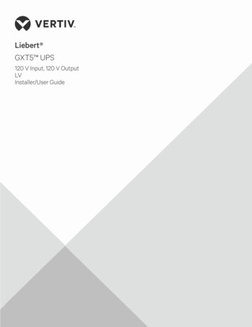
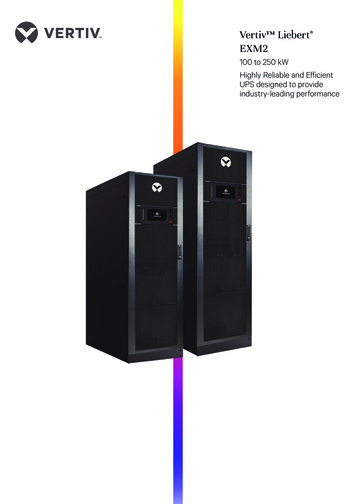
Vertiv NetSure -48 VDC Battery Rack SystemSystem Application GuideMAIN COMPONENTS ILLUSTRATIONSOutput LeadConnection PointsFront shield and portionof rack removed forclarity only.-48V (-BAT)GND/RTN ( BAT)FrontBatteryTrayBattery String CircuitBreaker (100A, 150A or 200A)Battery TrayFront CoverBatteryTrayBattery String CircuitBreaker (100A, 150A or 200A)Battery TrayFront CoverBatteryTrayBattery String CircuitBreaker (100A, 150A or 200A)Battery TrayFront CoverBatteryTrayBattery String CircuitBreaker (100A, 150A or 200A)Battery TrayFront CoverBatteryTrayBattery String CircuitBreaker (100A, 150A or 200A)Battery TrayFront CoverRearFrontSpec. No: 588820400100, 588820400150, 588820400200Model No: 48BA800-233SAG588820400100, SAG588820400150, SAG588820400200Revision D, March 11, 2021
Vertiv NetSure -48 VDC Battery Rack SystemSystem Application GuideDESCRIPTIONSBattery Rack Systems588820400100: Battery Rack System with 100 A Battery Disconnect Circuit BreakersFeatures Provides one assembled “stand-alone” battery rack. Includes (1) 27.5” wide x 22.6” deep x 84” tall box framework, (5)battery trays, battery termination busbar assemblies, (1) instruction manual, and packaging. Also includes factory routedand lugged cabling from each battery tray to the battery termination busbar assemblies. Also equipped with (5) left sidemounted 100 A battery disconnect circuit breakers. Factory circuit breaker alarm wiring is provided to an alarm card.The alarm card provides external relay contacts and resistive battery for connection to customer external alarm circuits. Eight (8) P/N 564901 Floor Anchor Reinforcing Plates are furnished with each battery rack.(2.0" x 2.0" x 0.25" thick, with a 1” diameter hole).RestrictionsFor use with a power system mounted in separate bay.Designed to accommodate the batteries listed under “Batteries” on page 7.Battery circuit breakers are E/M trip. E/M (Electrical/Mechanical) trip circuit breaker (black handle) provides an alarm duringand electrical or manual trip condition.The maximum total current is 400 A based on 80% of the total disconnect breaker rating.Ordering Notes1) Order one (1) 588820400100 per system for a system with 100 A battery circuit breakers.2) Order Battery Rack Isolation Kit, P/N 10019129, as required. See “Battery Rack Isolation Kit” on page 6.3) Order batteries separately. See “Batteries” on page 7.4) Order Battery Space Shim, P/N 564917, for use with certain batteries. See Table 1.5) Order Battery Retainer Kit, P/N 10010061, for use with certain batteries. See Table 1.588820400150: Battery Rack System with 150 A Battery Disconnect Circuit BreakersFeatures Provides one assembled “stand-alone” battery rack. Includes (1) 27.5” wide x 22.6” deep x 84” tall box framework, (5)battery trays, battery termination busbar assemblies, (1) instruction manual, and packaging. Also includes factory routedand lugged cabling from each battery tray to the battery termination busbar assemblies. Also equipped with (5) left sidemounted 150 A battery disconnect circuit breakers. Factory circuit breaker alarm wiring is provided to an alarm card.The alarm card provides external relay contacts and resistive battery for connection to customer external alarm circuits. Eight (8) P/N 564901 Floor Anchor Reinforcing Plates are furnished with each battery rack.(2.0" x 2.0" x 0.25" thick, with a 1” diameter hole).RestrictionsFor use with a power system mounted in separate bay.Designed to accommodate the batteries listed under “Batteries” on page 7.Battery circuit breakers are E/M trip. E/M (Electrical/Mechanical) trip circuit breaker (black handle) provides an alarm duringand electrical or manual trip condition.The maximum total current is 600 A based on 80% of the total disconnect breaker rating.Ordering Notes1) Order one (1) 588820400150 per system for a system with 150 A battery circuit breakers.2) Order Battery Rack Isolation Kit, P/N 10019129, as required. See “Battery Rack Isolation Kit” on page 6.3) Order batteries separately. See “Batteries” on page 7.4) Order Battery Space Shim, P/N 564917, for use with certain batteries. See Table 1.5) Order Battery Retainer Kit, P/N 10010061, for use with certain batteries. See Table 1.Spec. No: 588820400100, 588820400150, 588820400200Model No: 48BA800-234SAG588820400100, SAG588820400150, SAG588820400200Revision D, March 11, 2021
Vertiv NetSure -48 VDC Battery Rack SystemSystem Application Guide588820400200: Battery Rack System with 200 A Battery Disconnect Circuit BreakersFeatures Provides one assembled “stand-alone” 800 A battery rack. Includes (1) 27.5” wide x 22.6” deep x 84” tall box framework,(5) battery trays, battery termination busbar assemblies, (1) instruction manual, and packaging. Also includes factoryrouted and lugged cabling from each battery tray to the battery termination busbar assemblies. Also equipped with (5)left side mounted 200 A battery disconnect circuit breakers. Factory circuit breaker alarm wiring is provided to an alarmcard. The alarm card provides external relay contacts and resistive battery for connection to customer external alarmcircuits. Eight (8) P/N 564901 Floor Anchor Reinforcing Plates are furnished with each battery rack.(2.0" x 2.0" x 0.25" thick, with a 1” diameter hole).RestrictionsFor use with a power system mounted in separate bay.Designed to accommodate the batteries listed under “Batteries” on page 7.Battery circuit breakers are E/M trip. E/M (Electrical/Mechanical) trip circuit breaker (black handle) provides analarm during and electrical or manual trip condition.Ordering Notes1) Order one (1) 588820400200 per system for a system with 200 A battery circuit breakers.2) Order Battery Rack Isolation Kit, P/N 10019129, as required. See “Battery Rack Isolation Kit” on page 6.3) Order batteries separately. See “Batteries” on page 7.4) Order Battery Space Shim, P/N 564917, for use with certain batteries. See Table 1.5) Order Battery Retainer Kit, P/N 10010061, for use with certain batteries. See Table 1.Spec. No: 588820400100, 588820400150, 588820400200Model No: 48BA800-235SAG588820400100, SAG588820400150, SAG588820400200Revision D, March 11, 2021
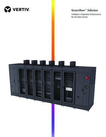
Vertiv NetSure -48 VDC Battery Rack SystemSystem Application GuideACCESSORY DESCRIPTIONSBattery Rack Isolation KitFeatures Provides electrical isolation of the battery rack from the concrete floor.Includes an insulating pad, four (4) insulating bushings, and four (4) flatwashers to be used with the anchors used to mount the battery rack to thefloor.Ordering Notes1) Order P/N 10019129 for a Battery Rack Isolation Kit to be used with588820400100, 588820400150, and 588820400200.Spec. No: 588820400100, 588820400150, 588820400200Model No: 48BA800-236SAG588820400100, SAG588820400150, SAG588820400200Revision D, March 11, 2021
Vertiv NetSure -48 VDC Battery Rack SystemSystem Application GuideBatteriesOrdering Notes1) Order four (4) batteries per battery string from Table 1 as required.2) For batteries that require an optional “Battery Spacer Shim”, order one shim per battery tray. See “Battery Spacer Shim,Part No. 564917” on page 9.3) For batteries that require a “Battery Retainer Kit”, order one (1) kit per battery tray. See “Battery Retainer Kit, Part No.10010061” on page 9.Manufacturer*ManufacturerP/NVertivP/N(12 VModule)Capacity(A-Hr)DimensionLxWxH(Inches)(per 12 V Module)Weight(lb)(per 12Vbattery)C&DTEL12-160F14045615120.16 x 4.86 x 11.14115C&DTEL12-180F--17420.16 x 4.86 x 12.6131C&DTEL12-210F55457920220.1 x 4.8 x 12.6132Deka12AVR-150ET12201815020.86 x 4.86 x 11.63115Deka12AVR-170ET54138117020.86 x 4.86 x 12.6120Deka12AVR-200ET--20024.30 x 4.97 x 12.74151DekaHT170ET--16420.86 x 4.86 x 12.58151DekaHT200ET--19024.15 x 4.97 x 12.74151Enersys12V155FS12201015520.75 x 4.92 x 11.14106.9Enersys12V170FS--17020.7 x 4.89 x 11.14112EnersysSBS 170F--17020.74 x 4.89 x 11.14116EnersysSBS 190F--19020.74 x 4.89 x FAT18012FAT181NSB155FT REDNSB170FT REDNSB190FT REDNSB155FT HTNSB170FT HTNSB190FT .97 x 4.96 x 9.0621.97 x 4.96 x 12.6421.97 x 4.96 x 12.6421.97 x 4.96 x 12.6422.00 x 4.90 x 11.0022.00 x 4.90 x 12.6022.00 x 4.90 x 12.6022.00 x 4.90 x 11.0022.00 x 4.90 x 12.6022.00 x 4.90 x 12.6095129134130101116123117121132GS YuasaPYL12V160FT--16021.90 x 4.90 x 11.00116.20GS YuasaPYL12V185FT--18521.90 x 4.90 x 11.00133.80Requires BatterySpacer Shim, PartNo. 564917Recommended 3Qty of ShimsRecommended 3Qty of ShimsRecommended 3Qty of ShimsRecommended 1Qty of ShimsRecommended 1Qty of Shims-Recommended 1Qty of Shims-Recommended 1Qty of ShimsRecommended 1Qty of ShimsRecommended 2Qty of ShimsRecommended 1Qty of ShimsNo info yetRecommended 1Qty of ShimsRecommended 1Qty of ShimsRequiresBattery RetainerKit, Part No.10010061-----Yes-Yes-----------------* See “Battery Manufacturer Information” on page 18.Table 1BatteriesSpec. No: 588820400100, 588820400150, 588820400200Model No: 48BA800-237SAG588820400100, SAG588820400150, SAG588820400200Revision D, March 11, 2021
Vertiv NetSure -48 VDC Battery Rack SystemSystem Application GuideCrimp LugsBattery Rack Equipment Grounding (Frame Ground) Lug Landing PointsA customer's grounding network lead can be attached to the top of each rack. Provision is made for installing a lead with atwo-hole lug that has 1/4" bolt clearance holes on 5/8" centers. Refer to Table 2 for lug selection. Refer to “Rack FrameGrounding Requirements” on page 10 for rack grounding information.Lead SizePart Number14 AWG to 10 AWG8 AWG6 AWG4 AWG2 gs should be crimped per lug manufacturer’s specifications.Table 2Crimp Lug (Two-Hole, 1/4” Bolt Clearance Hole, 5/8” Centers)Battery Rack Output Busbar Lug Landing PointsThe battery rack is equipped with top-mounted battery busbar termination assemblies which provide three (3) negativebattery rack output (-48V) and three (3) positive battery rack output (GND/RTN) lug landing points. These lug landing pointsprovide clearance holes for 3/8” bolts for installation of customer-provided two-hole lugs that have 1” centers and 3/8” boltclearance holes. Customer must provide lug mounting bolts and additional hardware. Refer to “Battery Rack Output LugLanding Dimensions” on page 16.The battery busbar termination assemblies are designed to accommodate the lugs listed in Table 3. Use Table 4 to selectrecommended battery rack output lead sizes and lugs for various loop lengths for the maximum battery rack output capacityrating (800 A). When making connections observe correct polarity.Battery Rack Output Lug Part NumbersLead SizePart Number6 AWG4 AWG2 AWG1/0 AWG2/0 AWG3/0 AWG4/0 AWG250 kcmil300 kcmil350 kcmil400 kcmil500 kcmil600 kcmil750 7800245347900245348000245348100Lugs should be crimped per lug manufacturer’s specifications.Table 3Crimp Lug (Two-Hole, 3/8” Bolt Clearance Hole, 1” Centers)Spec. No: 588820400100, 588820400150, 588820400200Model No: 48BA800-238SAG588820400100, SAG588820400150, SAG588820400200Revision D, March 11, 2021
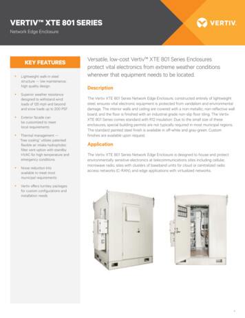
Vertiv NetSure -48 VDC Battery Rack SystemSystem Application GuideBattery Spacer Shim, Part No. 564917Features To ensure spacing between batteries, spacers are provided on the rearand front cover of each battery tray. For certain batteries of shorterlength, a shim is required between the front retaining bracket and thespacers. Kit includes ten (10) shims and the necessary hardware.RestrictionsShims are to be installed by customer.Ordering Notes1) Order one (1) kit of shims and hardware per battery rack, if required.See Table 1 for requirement.Battery Retainer Kit, Part No. 10010061Features This kit is used to accommodate batteries with a deeperprofile (longer length). Refer to Table 1 for batteriesrequiring this kit. This kit includes a front retaining bracket,a top retaining bracket, and installation hardware. This kit can be factory or field installed.Ordering Notes1) Refer to Table 1 for batteries requiring this kit. Order one(1) battery retainer kit P/N 10010061 for each battery trayusing batteries requiring this kit.Battery Retainer KitTop RetainerBracketFront RetainerBracketMounting View of Battery Retainer KitSpec. No: 588820400100, 588820400150, 588820400200Model No: 48BA800-239SAG588820400100, SAG588820400150, SAG588820400200Revision D, March 11, 2021
Vertiv NetSure -48 VDC Battery Rack SystemSystem Application GuideRECOMMENDED WIRE SIZES, BRANCH CIRCUIT PROTECTION, AND CRIMP LUGSRack Frame Grounding RequirementsFor rack grounding requirements, refer to the current edition of the American National Standards Institute (ANSI) approvedNational Fire Protection Association's (NFPA) National Electrical Code (NEC), applicable local codes, and your specific siterequirements.A customer's grounding network lead can be attached to the top of each rack. Provision is made for installing a lead with atwo-hole lug that has 1/4" bolt clearance holes on 5/8" centers. Refer to “Battery Rack Equipment Grounding (Frame Ground)Lug Landing Points” on page 8 for lug selection.Recommended Battery Rack Output Lead Wire Sizes800 Ampere Cable-Connected Stand-Alone Battery RackLug and Wire Size Selection for 800 Ampere Cable-Connected Stand-Alone Battery RackAmbient OperatingTemperature (1)Loop Length (Ft)1.0 Voltage Drop (2)71.4 40 C( 104 C)123Loop Length (Ft)Recm 90 C0.25 Voltage Drop (2) Wire Size (AWG) (1)17.8RecommendedCrimp Lug (3)(6) 1/0 AWG(6) 24534710075.618.9(4) 3/0 AWG(4) 245347300101.425.3(3) 300 kcmil(3) 245347600135.133.8(2) 600 kcmil(2) 245348000168.942.2(2) 750 kcmil(2) 245348100253.463.3(3) 750 kcmil(3) 245348100337.884.5(4) 750 kcmil(4) 245348100422.3105.6(5) 750 kcmil(5) 245348100506.8126.7(6) 750 kcmil(6) 245348100Wire sizes based on recommendations of the American National Standards Institute (ANSI) approved National FireProtection Association's (NFPA) National Electrical Code (NEC), Table 310.15 (B) (16) for copper wire at 90 Cconductor temperature. For operation in countries where the NEC is not recognized, follow applicable codes.Recommended wire sizes are sufficient to restrict voltage drop to the voltage shown in the column heading, or less, atrated full load output current of the system for the loop lengths shown in this column. Loop length is the sum of thelengths of the positive and negative leads.Two-hole lug, 3/8 bolt clearance hole, 1" centers. Lugs should be crimped per lug manufacturer’s specifications.Table 4Spec. No: 588820400100, 588820400150, 588820400200Model No: 48BA800-2310SAG588820400100, SAG588820400150, SAG588820400200Revision D, March 11, 2021
Vertiv NetSure -48 VDC Battery Rack SystemSystem Application Guide600 Ampere Cable-Connected Stand-Alone Battery RackLug and Wire Size Selection for 600 Ampere Cable-Connected Stand-Alone Battery RackAmbient OperatingTemperature (1)Loop Length (Ft)1.0 Voltage Drop (2) 40 C( 104 C)123Loop Length (Ft)Recm 90 C0.25 Voltage Drop (2) Wire Size (AWG) (1)RecommendedCrimp Lug (3)49.812.5(5) 2 AWG(5) 24534820063.415.9(4) 1/0 AWG(4) 24534710075.618.9(3) 3/0 AWG(3) 245347300105.126.3(2) 350 kcmil(2) 245347700120.130.0(2) 400 kcmil(2) 245347800150.237.5(2) 500 kcmil(2) 245347900180.245.0(2) 600 kcmil(2) 245348000225.256.3(2) 750 kcmil(2) 245348100337.884.5(3) 750 kcmil(3) 245348100Wire sizes based on recommendations of the American National Standards Institute (ANSI) approved National FireProtection Association's (NFPA) National Electrical Code (NEC), Table 310.15 (B) (16) for copper wire at 90 Cconductor temperature. For operation in countries where the NEC is not recognized, follow applicable codes.Recommended wire sizes are sufficient to restrict voltage drop to the voltage shown in the column heading, or less, atrated full load output current of the system for the loop lengths shown in this column. Loop length is the sum of thelengths of the positive and negative leads.Two-hole lug, 3/8 bolt clearance hole, 1" centers. Lugs should be crimped per lug manufacturer’s specifications.Table 5400 Ampere Cable-Connected Stand-Alone Battery RackLug and Wire Size Selection for 400 Ampere Cable-Connected Stand-Alone Battery RackAmbient OperatingTemperature (1)Loop Length (Ft)1.0 Voltage Drop (2) 40 C( 104 C)123Loop Length (Ft)Recm 90 C0.25 Voltage Drop (2) Wire Size (AWG) (1)RecommendedCrimp Lug (3)35.58.9(6) 6 AWG(6) 24534990047.011.8(5) 4 AWG(4) 24535000059.814.9(4) 2 AWG(4) 24534820071.417.8(3) 1/0 AWG(3) 24534710075.618.9(2) 3/0 AWG(2) 245347300135.133.8(1) 600 kcmil(1) 245348000168.942.2(1) 750 kcmil(1) 245348100337.884.5(2) 750 kcmil(q) 245348100506.8126.7(3) 750 kcmil(1) 245348100Wire sizes based on recommendations of the American National Standards Institute (ANSI) approved National FireProtection Association's (NFPA) National Electrical Code (NEC), Table 310.15 (B) (16) for copper wire at 90 Cconductor temperature. For operation in countries where the NEC is not recognized, follow applicable codes.Recommended wire sizes are sufficient to restrict voltage drop to the voltage shown in the column heading, or less, atrated full load output current of the system for the loop lengths shown in this column. Loop length is the sum of thelengths of the positive and negative leads.Two-hole lug, 3/8 bolt clearance hole, 1" centers. Lugs should be crimped per lug manufacturer’s specifications.Table 6Spec. No: 588820400100, 588820400150, 588820400200Model No: 48BA800-2311SAG588820400100, SAG588820400150, SAG588820400200Revision D, March 11, 2021
Vertiv NetSure -48 VDC Battery Rack SystemSystem Application GuideSPECIFICATIONS1.SYSTEM1.1 Output Ratings1.1.1 See page 1.1.2 Environmental Ratings1.2.1 Operating Ambient Temperature Range: 0 C to 40 C (32 F to 104 F).1.2.2 Storage Ambient Temperature Range: -40 C to 75 C (-40 F to 167 F).1.2.3 Humidity: This system is capable of operating in an ambient relative humidity range of 0% to 95%, non-condensing.1.2.4 Altitude: 0 feet (0 meters) to 12,000 feet (3657 meters). Derate operating ambient temperature range by 2 C per1000 feet (305 meters) above 5000 feet (1524 meters).1.2.5 Mounting: This product is intended only for installation in a restricted access location on or above a noncombustible surface.This product must be located in a controlled environment with access to crafts persons only.This product is intended for installation in network telecommunication facilities (CO, vault, hut, or otherenvironmentally controlled electronic equipment enclosure).This product is intended to be connected to the common bonding network in a network telecommunication facility(CO, vault, hut, or other environmentally controlled electronic equipment enclosure).The DC return connection to this system can remain isolated from system frame and chassis (DC-I).This system is suitable for installation as part of the Common Bonding Network (CBN).Clearance requirements are:a) Recommended minimum aisle space clearance for the front of each bay is 2'6".b) The battery rack is front accessed for installation, operation, and maintenance. Refer to your company’sstandards for recommended minimum aisle space clearance for the rear of each bay.1.3 Compliance Information1.3.1 Safety Compliance: This power board is UL Listed ("c UL") as a DC Power Distribution Center for CommunicationsEquipment. This unit meets the requirements of CSA 22.2, No. 225 and is tested and Certified by UL ("c UL") as aCustom Built Power Distribution Center for Communications Equipment.1.3.2 Seismic Compliance: NEBS Zone 4 Earthquake compliant with five battery strings.1.3.3 NEBS Compliance: Compliance verified by a Nationally Recognized Testing Laboratory (NRTL) per GR-1089-COREand GR-63-CORE. Contact Vertiv for NEBS compliance reports.Spec. No: 588820400100, 588820400150, 588820400200Model No: 48BA800-2312SAG588820400100, SAG588820400150, SAG588820400200Revision D, March 11, 2021
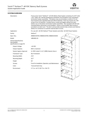
Vertiv NetSure -48 VDC Battery Rack SystemSystem Application GuideMECHANICAL SPECIFICATIONSOverall DimensionsNotes:1. All dimensions are in inches,unless otherwise specified.2. Weight in LBS.(minus batteries)Net: 484.50Shipping: 517.503. Finish: Textured Dark GrayBattery Tray Internal Dimensions:21.2 W x 21.0 D x 11.1 HTop ViewSpace between Installed BatteryTrays (from bottom of one tray tobottom of next tray): 1584.022.8Left Side ViewSpec. No: 588820400100, 588820400150, 588820400200Model No: 48BA800-2327.5Front View13Right Side ViewSAG588820400100, SAG588820400150, SAG588820400200Revision D, March 11, 2021
Vertiv NetSure -48 VDC Battery Rack SystemSystem Application GuideDimensions with Battery Retainer Kit (P/N 10010061)Notes:1. All dimensions are in inches,unless otherwise specified.2. Weight in LBS.(minus batteries)Net: 484.50Shipping: 517.503. Finish: Textured Dark GrayBattery Tray Internal Dimensions:21.2 W x 23.2 D x 12.7 HTop ViewSpace between Installed BatteryTrays (from bottom of one tray tobottom of next tray): 1584.025.1Left Side ViewSpec. No: 588820400100, 588820400150, 588820400200Model No: 48BA800-2327.5Front View14Right Side ViewSAG588820400100, SAG588820400150, SAG588820400200Revision D, March 11, 2021
Vertiv NetSure -48 VDC Battery Rack SystemSystem Application GuideFloor Mounting Dimensions27.4702.2586.25822.9342.26822.4342.51845 45 45 45 1.000 x 1.875 SLOT(8 PLACES)18.29622.81210.296FrontSpec. No: 588820400100, 588820400150, 588820400200Model No: 48BA800-2345 45 45 45 Bottom View15SAG588820400100, SAG588820400150, SAG588820400200Revision D, March 11, 2021
Vertiv NetSure -48 VDC Battery Rack SystemSystem Application GuideBattery Rack Output L
Vertiv NetSure -48 VDC Battery Rack System System Application Guide . Spec. 1No: 588820400100, 588820400150, 588820400200 SAG588820400100, SAG588820400150, SAG588820400200 . Battery Rack Systems . Enersys ; 12V155FS . 122010 ; 155 . 20.75 x 4.92 x 11.14 ; 106.9 . Recommended 1 Qty of Shims --