Transcription
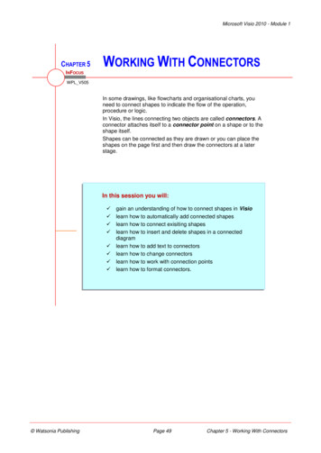
Microsoft Visio 2010 - Module 1CHAPTER 5WORKING WITH CONNECTORSINFOCUSWPL V505In some drawings, like flowcharts and organisational charts, youneed to connect shapes to indicate the flow of the operation,procedure or logic.In Visio, the lines connecting two objects are called connectors. Aconnector attaches itself to a connector point on a shape or to theshape itself.Shapes can be connected as they are drawn or you can place theshapes on the page first and then draw the connectors at a laterstage.In this session you will: Watsonia Publishinggain an understanding of how to connect shapes in Visiolearn how to automatically add connected shapeslearn how to connect exisiting shapeslearn how to insert and delete shapes in a connecteddiagramlearn how to add text to connectorslearn how to change connectorslearn how to work with connection pointslearn how to format connectors.Page 49Chapter 5 - Working With Connectors
Microsoft Visio 2010 - Module 1CONNECTING SHAPESThe shapes drawn from some stencils (e.g.flowcharts) have connection points. Thesepoints enable you to draw connectors betweenshapes to display a relationship between them.The connectors can be attached to the shapesusing either dynamic or point glue. Glue is aproperty that keeps shapes connected even whenthey are moved to new positions.Connection PointsA connection point is a special point on some shapes to which you can attach (or glue)connectors and other shapes. A connection point appears as a blue x – for example, the Createrequest and Decision shapes below each have four connection points.When you glue a connector to a connection point on a shape, the shape and connector will stayconnected even if you move the shape as you can see in the example below.In Visio 2010, connection points only become visible when you attempt to connect a shape toanother shape. You will see a shape’s connection points when you hover near a shape using theConnector tool or drag the endpoint of a connector or line near a shape that has connectionpoints.Connection pointConnectorConnectionsThere are two main types of connections in Visio: dynamic and point. What differentiates thesetwo connections is whether or not a connector remains glued to a specific connection point whenyou move the attached shape.A dynamic connection is one where the connector will move around the shape as you move theshape. Visio will always ensure the connector is the shortest, most direct line possible. You createa dynamic connection by selecting the entire shape (rather than the connection point) and connectit to another shape (rather than to a connection point).A point connection is one where the connector is glued on a connection point of a shape. Whenyou move this shape, the connector may change shape (i.e. to allow for other shapes in its way)but the connector will always remain attached to the same connection point. You create a pointconnection by connecting a specific connection point on one shape to another connection point onanother shape.Until you select a connector or move one of the attached shapes, you cannot differentiate adynamic connector from a point connector. Below, we have selected both connectors so you cansee how they differ. Both ends in a dynamic connector are surrounded by a blue box, while thestart point of a point connector is a hollow red box and its end point is a solid red square.Dynamic connection Watsonia PublishingPoint connectionPage 50Chapter 5 - Working With Connectors
Microsoft Visio 2010 - Module 1AUTOMATICALLY ADDING CONNECTED SHAPESThe AutoConnect feature in Visio lets youquickly add connected shapes to your drawingthat are evenly spaced and aligned. You caneither add the shapes by selecting one of the fourOpenFileTry This Yourself: Quick Shapes in the mini toolbar, or you canpre-select the desired shape in the Shapes windowand simply click on the AutoConnect arrow pointingin the direction where you want to add the shape.1Before starting this exercise youMUST open V505 Working WithConnectors 1.vsd.Hover over the Build modelProcess (rectangle) shape untilthe blue AutoConnect arrowsappear around the shape2Hover over the bottomAutoConnect arrow to display amini toolbar with the top fourQuick Shapes from the openBasic Flowchart ShapesstencilA preview of the shape that iscurrently selected in the stencilappears on the page Move the pointer over the fourshapes to see a live preview ofeach shape on the page7Click on the Decision(diamond) shape, then typeaccepted and click outside theshapeLet’s add another shape Click on Document in theShapes window to select thisshape in the stencilHover over the first Decisionshape, then hover over thebottom AutoConnect arrowClick on the AutoConnect arrowto add the Document, thentype Write problem reportConnections created using AutoConnect aredynamic connections.For Your Reference Handy to Know To automatically add connected shapes:1. Click on the shape in the stencil to be added2. Hover over the shape in the drawing, thenhover over the desired AutoConnect arrow3. Click on the Quick Shape in the mini toolbaror click on the AutoConnect arrow to add theselected shape You can turn AutoConnect on or off in theactive drawing by ticking or clearingAutoConnect in the Visual Aids group onthe View tab. You can turn it on or off for alldrawings in the Options dialog box. Click onFile, Options, Advanced and tick or clearEnable AutoConnect in Editing options. Watsonia PublishingPage 51Chapter 5 - Working With Connectors
Microsoft Visio 2010 - Module 1CONNECTING EXISTING SHAPESYou can connect existing shapes in a drawingusing AutoConnect (with the Pointer tool) ormanually with the Connector tool. To create apoint connection on the first shape (connectingSameFileTry This Yourself: from a connection point to another point or shape),you must use the Connector tool. By default,AutoConnect creates a dynamic connectionglueing the start of a connector to the shape.2Continue using the previous file oropen V505 Working WithConnectors 2.vsd.Hover over the Start shape todisplay the AutoConnect arrows,then hover over the bottom arrow todisplay a preview of a connectorClick on the AutoConnect arrow toinsert the connector, then drag theshape to a location similar to asshown to see that the connector canmove to a different connection point– this is a dynamic (shape to shape)connectionHover over the Develop Processshape, then click and drag thebottom AutoConnect arrow until theconnection point is highlighted, asshown, then release the mousebutton – this is a shape to pointconnection35Drag the Develop Process shapeback to its original position – theconnector will attach to theconnection point closest to theDecision shapeClick on the Connector toolinthe Tools group, then hover over theright connector point of the topDecision shape to select itClick on the connector point, thendrag to the centre of the BuildProcess shape, as shown, thenrelease the mouse button to create apoint to shape connection6You can use the Connector toolto create all four connectortypes: shape to shape, shape to point, point to shape, and point topoint. Using the Pointer tooland AutoConnect, you can onlycreate shape to shape and shape to point connectors.For Your Reference Handy to Know To connect existing shapes with a point toshape/point connection:1. Click on the Connector tool You can connect shapes using a connectorshape from a stencil. Once you havedragged the connector onto the page, drageach end of the connector to the desiredconnection point and glue it in position. If youare using a dynamic connector shape, youcan glue it to the shape or connection point.2. Click on the connection point and drag toeither the shape or connection point3. Release the mouse button Watsonia PublishingPage 52Chapter 5 - Working With Connectors
Microsoft Visio 2010 - Module 1INSERTING AND DELETING SHAPESIf you have already created much of yourflowchart but you need to add or remove shapes,it’s no problem. As you insert a shape, Visio willconnect the shapes, repositioning shapes asnecessary. When you delete a shape, Visio willautomatically connect the remaining shapes butwithout repositioning them. However, using AutoAlign & Space you can correct this with a click.SameFileTry This Yourself: Continue using the previousfile or open V505 Working WithConnectors 3.vsd.Drag the Document shapefrom the Basic FlowchartShapes stencil onto theconnector between the Startand Develop Process shapesuntil the two red connectionhandles appear12Release the mouse buttonThe surrounding shapes willmove automatically makingroom for the shape and a newconnector will be added.3If you want toensure that thespacing betweenevery shape in adrawing isconsistent, click onPositionin theArrange groupand select AutoSpace.You can easily remove shapesas well Ensure the new Documentshape is selected, then pressYou can changethe layout of aflowchartautomatically inVisio. To do this,click on ReLayout Pagein the Layoutgroup on theDesign tab andhover over thevarious options tosee a Live Previewof the diagram.Click on thedesired option.The two connectors will bereplaced by a single connectorbetween the remainingshapes. Let’s correct thespacing now Click on the Pointer tool ,then select both the Start andDevelop Process shapes,then click on Auto Align &Spacein the Arrangegroup4For Your Reference Handy to Know To insert a shape with automatic adjustment:1. Drag a shape to be inserted onto aconnectorTo delete a shape with automatic adjustment:1. Select the shape and press2. Select the shapes then click on Auto Align& Spaceto correct the spacing Visio does not automatically close up thespace when you delete a shape from a linkedsequence of shapes as this might not be theaction you desire. Watsonia Publishing You can adjust all shapes in a diagram at thesame time by selecting them and thenclicking on Auto Align & Space .Page 53Chapter 5 - Working With Connectors
Microsoft Visio 2010 - Module 1ADDING TEXT TO CONNECTORSIn some instances, you may need to add text to aconnector. In a flowchart, for example, you mightneed to indicate the direction of flow based onthe outcome of a decision. If the outcome is2SameFileTry This Yourself: Continue using the previousfile with this exercise, or openthe file V505 Working WithConnectors 4.vsd.Click on the Pointer toolthe Tools groupin3Click on the connectorbetween the acceptedDecision shape and the BuildProcess shape to select itType YesVisio will automatically add thetext to the selected connector.Visio may also zoom in if youare working at a magnificationless than 100% so that youcan see what you are typing 4Click outside the text toindicate that you have finishedentering the textYou could have also pressed positive, the flow will continue in one direction but ifthe outcome is negative, then the flow will beredirected elsewhere.5Repeat the above steps to addNo between the Decisionshape and the DocumentshapeFor Your Reference Handy to Know To add text to a connector:1. Click on the connector using the Pointertool You can format or edit the text on aconnector. To do this, select the connectorby clicking on it with the Pointer toolthenclick on the Text toolin the Tools groupto select the text.2. Type the desired text Watsonia PublishingPage 54Chapter 5 - Working With Connectors
Microsoft Visio 2010 - Module 1CHANGING CONNECTORSSometimes, the path that a connector makesbetween two shapes is not quite right. You canmanipulate a connector to reshape it. You canalso change the type of line that is used for aconnector from being right-angled to either curvedor straight. If you have connectors crossing otherconnectors in more complex flowcharts, you canchange the way the lines appear where they cross.SameFileTry This Yourself: Continue using the previousfile or open V505 Working WithConnectors 5.vsd.Use the Connector toolcreate a point to pointconnection as showntoYou can manipulate aconnector Click on the Pointer toolthen drag the two midpoints(the blue squares) and vertex(blue diamond) on theconnector as desired12You can create a newvertex in a connectorby holdingwhiledragging a midpoint.You can add extrasections to aconnector by holdingwhile dragging avertex or midpoint.3You can change the connectorto a different type of line Click on the Design tab, thenclick on Connectorsin theLayout group and selectStraight LinesRepeat step 3 but selectCurved Lines and thenmanipulate it as desiredUsing the Connectors menuyou can also add line jumps 6Using AutoConnect, create aconnector from the bottom ofthe Develop Process and glueit to the bottom of the Buildmodel ProcessRepeat step 3 and selectShow Line Jumps, then pressFor Your Reference Handy to Know To manipulate a connector:1. Click on the connector (Pointer tool If you want to reverse the direction of aconnector, select the connector, pressto delete it, and then create a new connectorin the correct direction.)2. Click on Connectorsin the Layoutgroup and selected the desired line type3. Drag the vertices and midpoints as needed Watsonia Publishing You can use different Line jumps settings byclicking on the dialog box launcherforLayout (on the Design tab).Page 55Chapter 5 - Working With Connectors
Microsoft Visio 2010 - Module 1WORKING WITH CONNECTION POINTSA connection point is a special point on someshapes to which you can glue connectors andother shapes. Although Visio provides a specificnumber of connection points in default locations,you can easily add additional points if you want toglue a connector in a non-standard location. Youcan also move and delete unwanted connectionpoints.2SameFileTry This Yourself: Continue using the previousfile or open V505 Working WithConnectors 6.vsd.Click on the Connection Pointtoolin the Tools group onthe Home tabThe existing connection pointswill display. Let’s add a newconnection point Click on the Develop Processshape to select it, then holdand click to the right of thebottom connection point3The connector willautomatically move to the newconnection point Repeat step 2 to add a newconnection point to the left ofthe bottom point on the BuildProcess shapeLet’s move the connector tothe new connection point 5Click on the Pointer tool ,then click on the connectorbetween the two ProcessesDrag the far right midpoint untilit is to the left of the othervertical connector, then dragthe red endpoint over your newconnection point – it will behighlighted in red as shown –then release the mouse buttonFor Your Reference Handy to Know To add a connection point:1. Click on the shape2. Click on the Connection Point tool You can move a selection point. Select theshape, click on the Connection Point tooland drag the connection point as desired. To delete a connection point, select theshape, click on the Connection Point tool, click on the connection point and press.3. Pressand click where desired Watsonia PublishingPage 56Chapter 5 - Working With Connectors
Microsoft Visio 2010 - Module 1FORMATTING CONNECTORSThere are multitudes of styles that you can applyto connectors to differentiate or highlight them.You may choose to alter the line width, colour orpattern, or you might want to have rounded linesrather than straight ones. You can also change thebeginning and ending styles of connectors. Thesedetailed formats mean that drawings can meeteven the most stringent of design criteria.2SameFileTry This Yourself: Continue using the previousfile or open V505 Working WithConnectors 7.vsd.Click on the Pointer tool ,then click on the connectorbetween the Document andthe Develop ProcessClick on the drop arrowforLinein the Shape groupand select Line Options toopen the Line dialog boxClick on the drop arrowforDash type and select 02Click on the drop arrowWeight and select 3 ptforClick on the drop arrowforColour and click on the firstcolour under StandardColours (Dark Red)56Click on the bottom left Roundcorners optionClick on [OK], then pressto deselect the line7For Your Reference Handy to Know To format a connector:1. Select the connector/s2. Click on the drop arrowfor Lineselect Line Options3. Select the required options4. Click on [OK] You can change a connection from beingdynamic to point and vice versa. To do this,select the connector and then drag theconnector end point away from the shape.Drag and drop the connector on a connectionpoint for a point connection, or on the middleof the shape for a dynamic connection. Watsonia PublishingandPage 57Chapter 5 - Working With Connectors
Microsoft Visio 2010 - Module 1NOTES:14 Watsonia PublishingPage 58Chapter 5 - Working With Connectors
shape. Visio will always ensure the connector is the shortest, most direct line possible. You create a dynamic connection by selecting the entire shape (rather than the connection point) and connect it to another shape (rather than to a connection point). A point connection is one where the connector is glued on a connection point of a shape. When