Transcription
15Surface ModelingLearning ObjectivesAfter completing this chapter you will be able to: Create Extruded surface. Create Revolved surface. Create Swept surface. Create Lofted surface. Create Planar surface. Create Fill surface. Create Radiated surface. Offset the surfaces. Trim the surfaces. Untrim the surfaces. Extend the surfaces. Knit the surfaces. Fillet the surfaces. Create a Mid-surface. Delete Holes. Replace the faces. Delete the faces. Move and Copy the surfaces. Thicken the surface body. Create thicken surface cut. Create a surface cut.c15-solidworks-2003.p6517/21/2003, 6:49 PM CADCIM Technologies, USA. For engineering services, contact sales@cadcim.comChapter
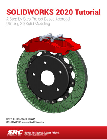
15-2SolidWorks for Designers CADCIM Technologies, USA. For engineering services, contact sales@cadcim.comSURFACE MODELINGSurface modeling is a technique of creating a planar or non planar geometry of zero thickness.This zero thickness geometry is known as surface. The surfaces are generally used to createmodels of complex shapes. You can convert surface models in solid models. You can alsoextract a surface from a solid model using the tools available for surface modeling. Thischapter explains the surface modeling tools available in SolidWorks. Using these tools, youcan create complex shapes as surfaces and then convert them in solid models, if required.Most of the real world components are created using solid modeling. But sometimes, youmay need to create some complex features that can only be created by surface manipulation.This manipulation of surfaces is done using surface modeling. After creating the requiredcomplex surface, you can convert it into a solid model. The reasons why you need to converta surface model into solid model is because a surface is a zero thickness geometry, and so ithas no mass and no mass properties. In real world design, many times you need mass andmass properties of a model. The other reason is that you can generate the section view only ifthe model is solid.In SolidWorks, the surface modeling is done in the Part mode and the tools used for surfacemodeling are available in the Surfaces toolbar. This toolbar is not available by default in thePart mode. Therefore, you need to invoke it by choosing View Toolbars Surfaces fromthe menu bar. The tools used for surface modeling are also available in the menu bar. ChooseInsert Surface from the menu bar to invoke the surface options. You will notice that someof the tools available in the Surfaces toolbar are the same as those discussed in solid modeling.These tools are extrude, revolve, sweep, and loft.The above mentioned tools and the other advanced surface modeling tools are discussednext.Creating an Extruded SurfaceToolbar:Menu:Surfaces Extruded SurfaceInsert Surface ExtrudeIn SolidWorks, the Extruded Surface tool is provided to extrude a closed or an opensketch to create an extruded surface. An extruded surface is created using theSurface-Extrude PropertyManager. After creating the sketch in the sketcherenvironment, choose the Extruded Surface button from the Surfaces toolbar. TheSurface-Extrude PropertyManager is displayed as shown in Figure 15-1. The preview of theextruded surface with the default value is also displayed in the drawing area. Using the draghandle provided in the drawing area, you can dynamically define the extrusion depth. Usingthe options available in the End Condition drop-down list, you can define the featuretermination. The feature termination options available in the Direction 1 and Direction 2rollouts and other options are the same as those discussed in part modeling.Figure 15-2 shows a closed sketch and Figure 15-3 shows the surface created by extruding theclosed sketch. Figure 15-4 shows an open sketch and Figure 15-5 shows the surface created byextruding that open sketch.c15-solidworks-2003.p6527/21/2003, 6:49 PM
15-3Figure 15-1 The Surface-Extrude PropertyManagerc15-solidworks-2003.p65Figure 15-2 A closed sketchFigure 15-3 Surface created by extruding the closedsketchFigure 15-4 An open sketchFigure 15-5 Surface created by extruding an opensketch37/21/2003, 6:49 PM CADCIM Technologies, USA. For engineering services, contact sales@cadcim.comSurface Modeling
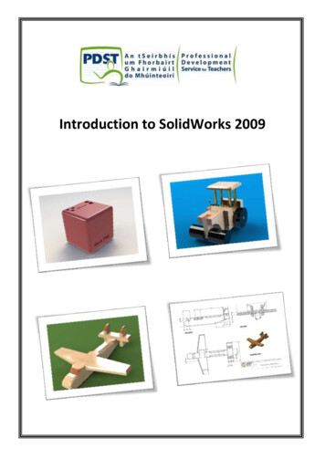
15-4SolidWorks for Designers CADCIM Technologies, USA. For engineering services, contact sales@cadcim.comCreating a Revolved SurfaceToolbar:Menu:Surfaces Revolved SurfaceInsert Surface RevolveYou can also create a surface by revolving a closed or an open sketch along a centerline.Revolving a sketch along a centerline to create a surface is similar to revolving asketch along a centerline to create a solid feature. To create a revolved surface, choosethe Revolved Surface button from the Surfaces toolbar after creating the sketch and thecenterline in the sketching environment. The Surface-Revolve PropertyManager will bedisplayed as shown in Figure 15-6. The preview of the revolved surface with the drag handleis displayed in the drawing area. The feature termination options and other options aresimilar to those discussed while revolving a solid feature.Figure 15-6 The Surface-Revolve PropertyManagerFigure 15-7 shows an open sketch for creating a revolve surface. Figure 15-8 shows the resultantrevolve surface.Figure 15-7 Sketch for creating a revolve surfacec15-solidworks-2003.p654Figure 15-8 Surface created by revolving asketch through an angle of 270-degree7/21/2003, 6:49 PM
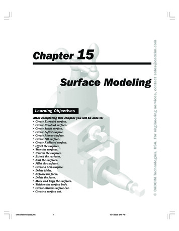
Surface Modeling15-5Toolbar:Menu:Surfaces Swept SurfaceInsert Surface SweepYou can also create a sweep surface by sweeping a closed or an open profile along aclosed or an open path. To create a swept feature, choose the Swept Surface buttonfrom the Surfaces toolbar. The Surface-Sweep PropertyManager is displayed as shownin Figure 15-9. You are prompted to select a sweep profile. Select a closed sketch or an opensketch as the profile of the sweep feature. Next, you are prompted to select the sweep path.Select a closed or an open sketch as the sweep path. The preview of the sweep feature will bedisplayed in the drawing area.Figure 15-9 The Surface-Sweep PropertyManagerYou can also select the guide curves while creating the sweep surface. All the other optionsused to create a sweep surface are similar to those discussed while creating the solid sweepfeature. Figure 15-10 shows an open profile and an open sketch and Figure 15-11 shows theresultant sweep surface. Figure 15-12 shows a closed profile and an open path and Figure 15-13shows the resultant sweep surface Figure 15-14 shows an open profile and closed path andFigure 15-15 shows the resultant sweep surface.c15-solidworks-2003.p6557/21/2003, 6:49 PM CADCIM Technologies, USA. For engineering services, contact sales@cadcim.comCreating a Swept Surface
CADCIM Technologies, USA. For engineering services, contact sales@cadcim.com15-6SolidWorks for DesignersFigure 15-10 Open profile and open pathFigure 15-11 Resultant sweep surfaceFigure 15-12 Closed profile and open pathFigure 15-13 Resultant sweep surfaceFigure 15-14 Open profile and closed pathFigure 15-15 Resultant sweep surfacec15-solidworks-2003.p6567/21/2003, 6:49 PM
15-7Figure 15-16 shows a closed profile and a closed path and Figure 15-17 shows the resultantsweep surface.Figure 15-16 Closed profile and closed pathFigure 15-17 Resultant sweep surfaceFigure 15-18 shows the profile, path, and the guide curves and Figure 15-19 shows the resultantsweep surface.Figure 15-18 Profile, path, and guide curvesFigure 15-19 Resultant sweep featureCreating a Lofted SurfaceToolbar:Menu:Surfaces Lofted SurfaceInsert Surface LoftIn SolidWorks, you can also create a surface by lofting two or more sections. To createa lofted surface, choose the Lofted Surface button from the Surfaces toolbar. TheSurface-Loft PropertyManager is invoked as shown in Figure 15-20 and you areprompted to select at least 2 profiles. Select the profiles to be lofted. All the options of creatinga lofted surface are similar to those are discussed while creating a solid lofted feature.Remember that if you need to create the loft surface with open section, then all the sections toc15-solidworks-2003.p6577/21/2003, 6:49 PM CADCIM Technologies, USA. For engineering services, contact sales@cadcim.comSurface Modeling
CADCIM Technologies, USA. For engineering services, contact sales@cadcim.com15-8SolidWorks for DesignersFigure 15-20 The Surface-Loft PropertyManagerbe lofted must be open. Similarly, if you need to create a closed lofted surface, then all thesections must be closed. The combination of closed and open sections in a loft surface is notpossible. Figure 15-21 shows two open sections to be lofted and Figure 15-22 shows the resultantlofted surface.Figure 15-21 Open sectionsFigure 15-22 Resultant lofted surfaceFigure 15-23 shows two closed sections to be lofted and Figure 15-24 shows the resultantlofted surface. Figure 15-25 shows two sections and the centerline and Figure 15-26 shows theresultant lofted surface.c15-solidworks-2003.p6587/21/2003, 6:49 PM
Figure 15-23 Closed sections15-9Figure 15-24 Resultant lofted surfaceTip. You do not need to add Pierce constraint if you are lofting the sections usingthe centerline.Figure 15-25 Sections and centerlineFigure 15-26 Resultant lofted surfaceFigure 15-27 shows two sections and the guide curves and Figure 15-28 shows the resultantlofted surface.Creating a Planar SurfaceToolbar:Menu:Surfaces Planar SurfaceInsert Surface PlanarA planar surface is generally used to fill the gaps between the surfaces using a planarpatch. To create a planar surface, you need to choose the Planar Surface button fromthe Surfaces toolbar or choose Insert Surface Planar from the menu bar. ThePlanar Surface PropertyManager is displayed as shown in Figure 15-29 and you are promptedto select a sketch, edge, or curve.c15-solidworks-2003.p6597/21/2003, 6:49 PM CADCIM Technologies, USA. For engineering services, contact sales@cadcim.comSurface Modeling
CADCIM Technologies, USA. For engineering services, contact sales@cadcim.com15-10SolidWorks for DesignersFigure 15-27 Sections and guide curvesFigure 15-28 Resultant lofted surfaceFigure 15-29 The Planar Surface PropertyManagerAfter invoking the Planar Surface PropertyManager, you need to select the bounding entities.The bounding entities can be sketch, edges, or curves. Select the bounding entities, the nameof the bounding entity is displayed in the Bounding Entities rollout. After selecting thebounding entities, choose the OK button from the Planar Surface PropertyManager. A planarsurface will be created using the selected entities.Creating a Fill SurfaceToolbar:Menu:Surfaces Filled SurfaceInsert Surface FillThe Filled Surface tool is used to create a surface patch along N number of sides.The sides to be selected for creating a fill surface can be the edges of the existingmodel, 2D or 3D sketch entities, or 2D or 3D curves. The difference between planarsurface and fill surface is that you cannot create planar surface using 3D curves or edges. Forexample, the 3D edge created in Figure 15-30 cannot be used to create planar surface. Butyou can fill this gap by creating a fill surface on the 3D edge.To create a fill surface, choose the Filled Surface button from the Surfaces toolbar. The Fillc15-solidworks-2003.p65107/21/2003, 6:49 PM
15-11Figure 15-30 Entities selected for creating a fill surfaceSurface PropertyManager is displayed as shown in Figure 15-31 and you are prompted toselect the bounding entities and set the options. Select entities which will define the boundary.Figure 15-31 The Fill Surface PropertyManagerc15-solidworks-2003.p65117/21/2003, 6:49 PM CADCIM Technologies, USA. For engineering services, contact sales@cadcim.comSurface Modeling
CADCIM Technologies, USA. For engineering services, contact sales@cadcim.com15-12SolidWorks for DesignersThe selected entities are displayed in green and the callouts attached to them are also displayed.After selecting the last entity that will close the current selection chain, the preview of thesurface is displayed in the drawing area and the mesh is also displayed. Now, choose the OKbutton from the Fill Surface PropertyManager. Figure 15-32 shows the preview of the fillsurface along with the mesh and Figure 15-33 shows the resultant fill surface.Figure 15-32 Preview of the fill surface alongwith meshFigure 15-33 Resultant fill surfaceNoteThe surface model used in the above example is created by trimming the surface. You will learnabout trimmed surfaces later in this chapter.The other options available in the Fill Surface PropertyManager are discussed next.Edge settingsThe options available in the Edge settings area are used to define various parameters tospecify the references with respect to the selected edges, type of curvature, and so on. Theseoptions are discussed next.Alternate FaceThe Alternate Face button available in the Edge settings area is used to specify the facereference to be included while creating a fill surface for controlling the curvature of thefill surface. This option is only used when you are creating a fill surface on a solid body.Curvature ControlThe Curvature Control drop-down list is used to define the type of curvature you need toapply on the fill surface that you are creating. There are two types of curvatures that youcan apply, these two types of curvatures are discussed next.c15-solidworks-2003.p65ContactThe Contact option is selected by default and is used to create a patch using the fillsurface option within the selected patch boundary.127/21/2003, 6:49 PM
15-13TangentThe Tangent option is used to create a patch using the fill surface option within theselected patch boundary but it also maintains the tangency of the patch created withthe selected edges. When you use this option for creating a patch, the Reverse Surfacebutton is also displayed. Using this button, you can reverse the direction of the surfacecreated.Figure 15-34 shows the circular edge selected as patch boundary. Figure 15-35 showsthe fill surface created using the Contact option selected from the Curvature Controldrop-down list. Figure 15-36 shows the fill surface created using the Tangent optionselected from the Curvature Control drop-down list.Figure 15-34 Edge selected as patch boundaryFigure 15-35 Fill surface created using theContact optionc15-solidworks-2003.p6513Figure 15-36 Fill surface created using theTangent option7/21/2003, 6:49 PM CADCIM Technologies, USA. For engineering services, contact sales@cadcim.comSurface Modeling
CADCIM Technologies, USA. For engineering services, contact sales@cadcim.com15-14SolidWorks for DesignersApply to all edgesThis option is used to apply the curvature settings discussed earlier to all the edges. Ifthis check box is not selected, the current curvature setting is only applied to the edge ofthe boundary selected in the Patch boundary display area.Optimize surfaceThe Optimize surface option is used to create the simplest patch of surface along theselected patch boundary. The Optimize surface check box is selected by default. Whenyou create a surface patch using the Optimize surface check box selected, the time takento create the surface is less and the model rebuilds faster. When you clear this check box,the Resolution Control rollout is displayed as shown in Figure 15-37. The slider availablein this rollout is used to specify the resolution of the fill surface. The higher the resolution,better will be the quality of the surface and the more time it will take to rebuild the model.Lower the resolution, the quality of the surface will not be good. However in this case, therebuilding of the model will take lesser time.Figure 15-37 The Resolution Control rolloutShow PreviewThe Show Preview check box is selected by default and is used to display the preview ofthe fill surface created using the selected patch boundary.Preview MeshThe Preview Mesh check box is selected by default and is used to display the meshsurface in the preview of the fill surface. This option is only available if the Show Previewcheck box is selected earlier.Constraint CurvesThe Constraint Curves rollout is used to define the constraint curves while creating the fillsurface. To create a fill surface using the constraining curves, invoke the Fill SurfacePropertyManager and then select the patch boundary. Now, click once in the ConstraintCurves area of the Constraint Curves rollout to invoke the selection mode and then selectthe constraint curves. The constraint curve to be selected can be a sketched entity, edge, or acurve. The select constraint curve is displayed in red and the callout is displayed attached toit. The name of the selected entity is displayed in the Constraint Curve display area. Thepreview of the fill surface modifies as you select the constraint curves. After specifying all theconstraint curves, choose the OK button from the Fill Surface PropertyManager.Figure 15-38 shows the sketches selected for patching the boundary and the constraintcurves. Figure 14-39 shows the resultant fill surface.c15-solidworks-2003.p65147/21/2003, 6:49 PM
15-15Figure 15-38 Sketches to be selected for patchingthe boundary and the constraint curvesFigure 15-39 Resultant fill surfaceCreating a Radiated SurfaceToolbar:Menu:Surfaces Radiate SurfaceInsert Surface RadiateIn SolidWorks, you can also create a surface by radiating a surface along an edge oredges or a split line. The radiated surface is always created parallel to the plane orface selected as radiate direction reference. This type of surface is generally used inmold design as the parting surface for extracting the core and cavity. For creating a radiatedsurface, choose the Radiate Surface button from the Surfaces toolbar. The Radiate SurfacePropertyManager is displayed as shown in Figure 15-40.Figure 15-40 The Radiate Surface PropertyManagerc15-solidworks-2003.p65157/21/2003, 6:49 PM CADCIM Technologies, USA. For engineering services, contact sales@cadcim.comSurface Modeling
CADCIM Technologies, USA. For engineering services, contact sales@cadcim.com15-16SolidWorks for DesignersYou will observe that the selection is active in the Radiate Direction Reference display area.Therefore, first you need to select a plane or a planar face parallel to which the surface will beradiated. The selected reference will be highlighted in green and an arrow symbol normal tothe selected face will be displayed. Now, the selection mode in the Edges to Radiate displayarea is invoked and you need to select the edges along which the surface will be radiated.Select the edges. The name of the selected edges is displayed in the Edges to Radiate displayarea and the arrows showing the direction in which the surface will be radiated is also displayedattached to the selected edges. Now, set the value of the distance of the surface to radiate inthe Radiate Distance spinner. After setting the radiate distance, choose the OK button fromthe Radiate Surface PropertyManager.The Propagate to tangent faces check box is used to radiate the surfaces along all the edgesthat are tangent to the selected edge.Figure 15-41 shows the radiate direction reference and the edge to be selected. Figure 15-42shows the resultant radiated surface with the Propagate to tangent faces check box selected.Figure 15-41 Reference and edge to be selectedFigure 15-42 Resultant radiated surface with thePropagate to tangent faces check box selectedOffsetting the SurfacesToolbar:Menu:Surfaces Offset SurfaceInsert Surface OffsetThe Offset Surface tool is used to offset the selected surface or surfaces to a givendistance. For offsetting a surface, choose the Offset Surface button from the Surfacestoolbar. The Offset Surface PropertyManager is displayed as shown in Figure 15-43and you are prompted to select a face or a surface to offset.Now, select the face or surface that you need to offset. The selected face or surface is highlightedin green and its name is displayed in the Surface or Faces to Offset display area. The previewof the offset surface with the default value is also displayed in the drawing area. Set the valueof the offset distance using the Offset Distance spinner. You can also flip the direction of thesurface creation using the Flip Offset Direction button available on the left of the Offsetc15-solidworks-2003.p65167/21/2003, 6:49 PM
15-17Figure 15-43 The Offset Surface PropertyManagerDirection spinner. After setting all the parameters, choose the OK button from the OffsetDistance PropertyManager. Figure 15-44 shows the surface selected to offset and Figure 15-45shows the resultant offset surface.Figure 15-44 Surface selected to offsetFigure 15-45 Resultant offset surfaceTip. If you need to extract a surface from the solid or a surface body withoutspecifying the offset distance, then invoke the Offset Surface PropertyManagerand select the surfaces that you need to extract. Set the value of the Offset Distancespinner to 0 and choose the OK button from the Offset Surface PropertyManager.Trimming the SurfacesToolbar:Menu:Surfaces Trimmed SurfaceInsert Surface TrimThe Trimmed Surface tool is used to trim the surface using a trim tool. A trim toolcan be a surface, sketched entity, or an edge. To trim a surface, choose the TrimmedSurface button from the Surfaces toolbar. The Trim Surface PropertyManager isdisplayed as shown in Figure 15-46 and you are prompted for selecting a trimming surface orsketch followed by the pieces to keep.c15-solidworks-2003.p65177/21/2003, 6:49 PM CADCIM Technologies, USA. For engineering services, contact sales@cadcim.comSurface Modeling
CADCIM Technologies, USA. For engineering services, contact sales@cadcim.com15-18SolidWorks for DesignersFigure 15-46 The Trim Surface PropertyManagerThe Trim tool radio button is selected by default. The trimming of surfaces using this optionis discussed next.When you invoke this tool, you will notice that the cursor is replaced by the trim tool cursor.Select the trimming surface using this cursor. You can select a surface, sketch, or an edge. Theselected entity is highlighted in green and the name of the trimming surface is displayed inthe Trimming Surfaces display area. The selection mode in the Pieces to keep display area isactive and you are prompted to select the pieces to keep. Also, the cursor is replaced by thesurface body cursor. Move the cursor on the surface that is being trimmed, the pieces of thesurface on which you place the cursor are displayed in blue. Select the piece or pieces of thesurface to keep. The selected pieces will be displayed in yellow and their names will be displayedin the Pieces to keep display area. Choose the OK button from the Trim SurfacePropertyManager.Figure 15-47 shows the trimming surface and the piece to keep after trimming. Figure 15-48shows the resultant trimmed surface. Figure 15-49 shows the sketch selected as a trimmingsurface and Figure 15-50 shows the resultant trimmed surface.The other method of trimming a surface is known as Mutual trim method. In this method,you need to select two surfaces as trimming surfaces. To trim the surfaces using this method,invoke the Trim PropertyManager and then choose the Mutual trim radio button from theTrim Type rollout. You are prompted to select the surfaces to trim, followed by the pieces tokeep. Select the trimming surfaces and then select the pieces to keep, refer to Figure 15-51and choose the OK button from the Trim PropertyManager. Figure 15-52 shows the resultanttrimmed surface.c15-solidworks-2003.p65187/21/2003, 6:49 PM
15-19Figure 15-47 Trimming surface and piece tokeep after trimming the surfaceFigure 15-48 Resultant trimmed surfaceFigure 15-49 Sketch selected as trimming surfaceFigure 15-50 Resultant trimmed surfaceFigure 15-51 Surfaces to trim and the pieces tokeepFigure 15-52 Resultant trimmed surfacec15-solidworks-2003.p65197/21/2003, 6:49 PM CADCIM Technologies, USA. For engineering services, contact sales@cadcim.comSurface Modeling
15-20SolidWorks for Designers CADCIM Technologies, USA. For engineering services, contact sales@cadcim.comUntrimming the SurfaceToolbar:Menu:Surfaces Untrim SurfaceInsert Surface Untrim(Customize to Add)The Untrim Surface tool is used to create a surface patch by extending the existingsurfaces. Using this option, the trimmed portion of a surface is filled with a surfacepatch. To untrim a surface, choose Insert Surface Untrim from the menu bar.You can also use the Untrim Surface button from the Surfaces toolbar, but you first need tocustomize this button. As you invoke this tool, the Untrim PropertyManager isinvoked as shown in Figure 15-53 and you are prompted to select surface bodies or edges ofsurface for the Untrim operation.Figure 15-53 The Untrim Surface PropertyManagerThere are two methods of untrimming the surfaces. In the first method, you will select theface that you need to untrim and in the second method you will select the edges of thetrimmed portion of the surface. Both these methods are discussed next.Untrimming by Selecting the FacesIn this method you will untrim the surface by selecting the face or faces of the surface tountrim. Invoke the Untrim PropertyManager and select the face of the surface that you needto untrim. The preview of the untrimmed surface with default settings is displayed in thedrawing area. Additional options are also displayed in the Options rollout as shown inFigure 15-54. These options are discussed next.Face untrim typeThe Face untrim type area is used to specify the type of edges along which you need tountrim the surface. The options available in this area are discussed next.c15-solidworks-2003.p65All edgesThe All edges radio button is selected by default. Therefore, all the internal and207/21/2003, 6:49 PM
15-21Figure 15-54 The Options rolloutexternal edges of the selected surface are extended to be untrimmed. Figure 15-55shows the surface to be selected and Figure 15-56 shows the untrimmed surface usingthe All edges radio button selected.Figure 15-55 Surfaces selected to untrimFigure 15-56 Resultant untrimmed surfacewith the All edges radio button selectedInternal edgesThe Internal edges radio button is used if you need to patch only the internal edgesof the selected surface using the Untrim Surface tool. Figure 15-57 shows theuntrimmed surface created with the Internal edges radio button selected.External edgesThe External edges radio button is used if you need to patch only the external edgesof the selected surface using the Untrim Surface tool. Figure 15-58 shows theuntrimmed surface created with the External edges radio button selected.Merge with originalThe Merge with original check box is selected to merge the surface created using thistool with the original surface. This check box is selected by default. If you clear this checkbox, the resultant untrimmed surface will be a separate surface body.You can also specify the percentage of distance to which you need to extend the surfacedepending on the edges type selected from the Face untrim type area of the Optionsc15-solidworks-2003.p65217/21/2003, 6:49 PM CADCIM Technologies, USA. For engineering services, contact sales@cadcim.comSurface Modeling
CADCIM Technologies, USA. For engineering services, contact sales@cadcim.com15-22SolidWorks for DesignersFigure 15-57 Resultant untrimmed surfacewith the Internal edges radio button selectedFigure 15-58 Resultant untrimmed surfacewith the External edges radio button selectedrollout. The Distance spinner is used to define the percentage distance of extension ofsurface. The preview of the surface extension is displayed in the drawing area.Untrimming by Selecting the EdgesYou can also patch a trimmed surface using the Untrim Surface tool by selecting the edges ofthe trimmed portion of the surface. Invoke the Untrim Surface PropertyManager and selectthe edge of the surface along which you need to patch the trimmed surface. Now, select theedge, additional options in the Options rollout are displayed as shown in Figure 15-59. Theoptions available in this rollout are discussed next.Figure 15-59 The Options rollout displayed when the Edge isselected to be patched using the Untrim Surface toolEdge untrim typeThe Edge untrim type area is used to specify the options to patch the trimmed surfaceusing the selected edges. The options available in this rollout are discussed next.c15-solidworks-2003.p65Extend edgesThe Extend edges radio button is selected by default and it extends the edge tocreate a corner to untrim the trimmed surface.Connect endpointsThe Connect endpoints radio button is used to patch the trimmed surface by joiningthe endpoints of the selected edge.227/21/2003, 6:49 PM
15-23Figure 15-60 shows the edge to be selected for untrimming a surface. Figure 15-61 showsan untrimmed surface created using the Extend edges check box selected. Figure 15-62shows the untrimmed surface created using the Connect endpoints check box selected.Figure 15-60 Edge selected for untrimming the surfaceFigure 15-61 Untrimmed surface createdwith Extend edges radio button selectedFigure 15-62 Untrimmed surface created withConnect endpoints radio button selectedExtending the SurfacesToolbar:Menu:Surfaces Extended SurfaceInsert Surface ExtendThe Extended Surface tool is used to extend the surface along the selected edge orthe selected face. To extend the surface, choose the Extended Surface button fromthe Surfaces toolbar. The Extend Surface PropertyManager is displayed as shown inFigure 15-63 and you are prompted to select a face or edge(s) and set the properties. Thereare two options of extending a surface, both of which are discussed next.c15-solidworks-2003.p65237/21/2003, 6:49 PM CADCIM Technologies, USA. For engineering services, contact sales@cadcim.comSurface Modeling
CADCIM Technologies, USA. For engineering servic
In SolidWorks, you can also create a surface by lofting two or more sections. To create a lofted surface, choose the Lofted Surface button from the Surfaces toolbar. The Surface-Loft PropertyManager is invoked as shown in Figure 15-20 and you are prompted to select at least 2 profiles. Sele