Transcription
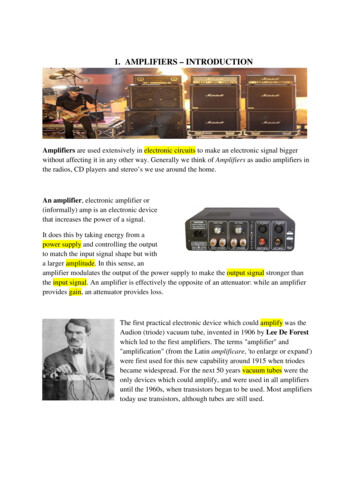
1. AMPLIFIERS – INTRODUCTIONAmplifiers are used extensively in electronic circuits to make an electronic signal biggerwithout affecting it in any other way. Generally we think of Amplifiers as audio amplifiers inthe radios, CD players and stereo’s we use around the home.An amplifier, electronic amplifier or(informally) amp is an electronic devicethat increases the power of a signal.It does this by taking energy from apower supply and controlling the outputto match the input signal shape but witha larger amplitude. In this sense, anamplifier modulates the output of the power supply to make the output signal stronger thanthe input signal. An amplifier is effectively the opposite of an attenuator: while an amplifierprovides gain, an attenuator provides loss.The first practical electronic device which could amplify was theAudion (triode) vacuum tube, invented in 1906 by Lee De Forestwhich led to the first amplifiers. The terms "amplifier" and"amplification" (from the Latin amplificare, 'to enlarge or expand')were first used for this new capability around 1915 when triodesbecame widespread. For the next 50 years vacuum tubes were theonly devices which could amplify, and were used in all amplifiersuntil the 1960s, when transistors began to be used. Most amplifierstoday use transistors, although tubes are still used.
Worksheet No.1Exercise 1. Reading Comprehension : Answer the questions.1. What is an amplifier?2. How does an amplifier work?3. What was the first „amplifier“ called?4. When and who was it invented by?5. When did people begin to use transistors?Exercise 2. Complete the highlighted words to the definitions.1. to enlarge or expand -2. an increase in wealth or resources -3. are composed of individual electronic components, such as resistors,transistors, capacitors, inductors and diodes, connected by conductive wires or traces throughwhich electric current can flow.4. The of a periodic variable is a measure of its change over a singleperiod (such as time or spatial period).5. signal that comes out of an electronic system -6. are devices that control electric current through a vacuum in a sealedcontainer.7. an electronic device that supplies electric energy to an electrical load -8. signal going into an electronic system -Exercise 3. Speaking1. What amplifiers do you use daily around the home? Name the devices.2. Do you know any famous amplifier brands? What is your favourite one?3. What is the brand of your hi-fi audio, car, guitar, etc. amplifier?
2. SIGNALA signal as referred to in communication systems, signal processing, and electricalengineering "is a function that conveys information about the behavior or attributes of somephenomenon".In the physical world, any quantity exhibiting variation in time or variation in space (such asan image) is potentially a signal that might provide information on the status of a physicalsystem, or convey a message between observers, among other possibilities.The IEEE (The Institute of Electrical and Electronics Engineers) Transactions on SignalProcessing states that the term "signal" includes audio, video, speech, image, communication,geophysical, sonar, radar, medical and musical signals.In electronics, a signal is an electric current or electromagnetic field used to convey data fromone place to another. The simplest form of signal is a direct current (DC) that is switched onand off; this is the principle by which the early telegraph worked. More complex signalsconsist of an alternating-current (AC) or electromagnetic carrier that contains one or moredata streams.input signal - signal going into an electronic system (MP3, microphone, camera.)output signal - signal that comes out of an electronic system (loudspeaker, oscilloscope,another amplifier.)
Worksheet No.2Exercise 1. Reading Comprehension: Answer the questions.1.2.3.4.5.What does a signal convey?What does IEEE stand for?What does the term signal include according to the IEEE?What is the definition of a signal in electornics?What does DC and AC stand for?Exercise 2. Name the type of signal (input/output) in these devices:a.d.b.e.c.
Exercise 3. Complete the article with the words from the box.alternating current, signal, circuits, generates, convert, direction, power supplyIn actuality, the amplifier 1. a completely new output signal based on the inputsignal. You can understand these signals as two separate 2. The output circuit isgenerated by the amplifier's 3. , which draws energy from a battery or poweroutlet. If the amplifier is powered by household 4. , where the flow of chargechanges directions, the power supply will 5. it into direct current, where thecharge always flows in the same 6. . The power supply also smoothes out thecurrent to generate an absolutely even, uninterrupted 7. . The output circuit'sload (the work it does) is moving the speaker cone.
3. TRANSISTORSTransistors are the semiconductor devices with three terminals. The three terminals arecalled emitter, collector and base. Transistor is operated in three configurations called ascommon base, common emitter and common collector. Transistor is used for voltage andcurrent amplification according to configurations. At base input signal of small amplitude isgiven and magnified output signal is collected at collector. Thus transistors help in achievingamplification of signal. By passing input current signal from region of low resistance toregion of high resistance amplification is achieved in transistors.Transistors of two types: Unipolar junction transistorBipolar junction transistorUNIPOLAR JUNCTION TRANSISTORThe current condition in unipolar transistor is due to only one type of charge carriers, majoritycarriers.The field-effect transistor (FET) is a transistor that uses an electric field to control the shapeand hence the electrical conductivity of a channel of one type of charge carrier in asemiconductor material. FETs are also known as unipolar transistors as they involve singlecarrier-type operation. The FET has several forms, but all have high input impedance. Whilethe conductivity of a non-FET transistor is regulated by the input current (the emitter to basecurrent) and so has a low input impedance, a FET's conductivity is regulated by a voltageapplied to a terminal (the gate) which is insulated from the device. The applied gate voltageimposes an electric field into the device, this in turn attracts or repels charge carriers to orfrom the region between a source terminal and a drain terminal. The density of chargecharacters in turn influences the conductivity between the source and drain.
The FET's three terminals are: Source (S), through which the carriers enter the channel. Conventionally, currententering the channel at S is designated by IS. Drain (D), through which the carriers leave the channel. Conventionally, currententering the channel at D is designated by ID. Drain-to-source voltage is VDS. Gate (G), the terminal that modulates the channel conductivity. By applying voltageto G, one can control ID.BIPOLAR JUNCTION TRANSISTORIn bipolar transistor the current condition is due to both types of charge carriers, holes andelectrons. So it is called bipolar. It is also referred as BJT.These two kinds of charge carriers are characteristic of the two kinds of doped semiconductormaterial; electrons are majority charge carriers in n-type semiconductors, whereas holes aremajority charge carriers in p-type semiconductors. In contrast, unipolar transistors such asthe field-effect transistors have only one kind of charge carrier.NPN is one of the two types of bipolar transistors, consisting of a layer of P-dopedsemiconductor (the "base") between two N-doped layers.The other type of BJT is the PNP, consisting of a layer of N-doped semiconductor betweentwo layers of P-doped material.
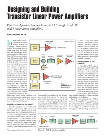
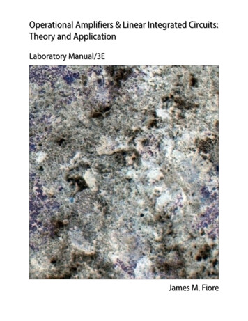
CONSTRUCTION OF BJT:If a p-region is sandwiched between two n-regions like shown in figure(a), then its n-p-ntransistor.a.If a n-region is sandwiched between two p-regions like shown in figure(b), then its p-n-ptransistor.b.
PARTS OF TRANSISTORS1. BASE- It is the middle region of the transistor. It is lightly doped and it is very thin.2. EMITTER AND COLLECTOR- These are the other two regions of transistors. Theseregions are heavily doped. Emitter’s doping level is slightly greater than that ofcollector and collector region-area is
Worksheet No.3Exercise 1. What types of transistors can you see in the pictures ? What do the letters standfor? Write the words.a.G C D E S b.B C E NPN PNP
Exercise 2. Decide if the statements are true or false. Correct the false statements.1. FETs are also known as bipolar transistors.2. The carriers leave the channel through GATE.3. In bipolar transistor the current condition is due to both types of charge carriers,holes and electrons.4. Majority charge carriers in n-type semiconductors are holes, whereas majoritycharge carriers in p-type semiconductors are electrons.5. BASE is the middle region of the transistor which is heavily doped and it is verythick.6. If a p-region is sandwiched between two n-regions then its n-p-n transistor.
4. Classification of AmplifiersThere are many forms of electronic circuits classed as amplifiers, from OperationalAmplifiers and Small Signal Amplifiers up to Large Signal and Power Amplifiers. Theclassification of an amplifier depends upon the size of the signal, large or small, its physicalconfiguration and how it processes the input signal, that is the relationship between inputsignal and current flowing in the load.The type or classification of an amplifier is given in the following table.Type of SignalClassificationSmall SignalType ofConfigurationCommon EmitterLarge SignalCommon BaseClass B AmplifierCommon CollectorClass A AmplifierClass AB AmplifierClass C AmplifierFrequency ofOperationDirect Current (DC)Audio Frequencies(AF)Radio Frequencies(RF)VHF, UHF and SHFFrequenciesGenerally, amplifiers can be sub-divided into two distinct types depending upon their poweror voltage gain. One type is called the Small Signal Amplifier which include pre-amplifiers,instrumentation amplifiers etc. Small signal amplifies are designed to amplify very smallsignal voltage levels of only a few micro-volts (µV) from sensors or audio signals.The other type are called Large Signal Amplifiers such as audio power amplifiers or powerswitching amplifiers. Large signal amplifiers are designed to amplify large input voltagesignals or switch heavy load currents as you would find driving loudspeakers.Power AmplifiersThe Small Signal Amplifier is generally referred to as a “Voltage” amplifier because theyusually convert a small input voltage into a much larger output voltage. Sometimes anamplifier circuit is required to drive a motor or feed a loudspeaker and for these types ofapplications where high switching currents are needed Power Amplifiers are required.As their name suggests, the main job of a “Power Amplifier” (also known as a large signalamplifier), is to deliver power to the load, and as we know from above, is the product of thevoltage and current applied to the load with the output signal power being greater than theinput signal power. In other words, a power amplifier amplifies the power of the input signalwhich is why these types of amplifier circuits are used in audio amplifier output stages todrive loudspeakers.The classification of an amplifier as either a voltage or a power amplifier is made bycomparing the characteristics of the input and output signals by measuring the amount of timein relation to the input signal that the current flows in the output circuit.
With the introduction to the amplifier of a Base bias voltage, different operating ranges andmodes of operation can be obtained which are categorized according to their classification.These various mode of operation are better known as Amplifier Class.Audio power amplifiers are classified in an alphabetical order according to their circuitconfigurations and mode of operation. Amplifiers are designated by different classes ofoperation such as class “A”, class “B”, class “C”, class “AB”, etc. These different AmplifierClasses range from a near linear output but with low efficiency to a non-linear output but witha high efficiency.No one class of operation is “better” or “worse” than any other class with the type ofoperation being determined by the use of the amplifying circuit. There are typical maximumefficiencies for the various types or class of amplifier, with the most commonly used being: Class A Amplifier – has low efficiency of less than 40% but good signalreproduction and linearity. Class B Amplifier – is twice as efficient as class A amplifiers with a maximumtheoretical efficiency of about 70% because the amplifying device only conducts (anduses power) for half of the input signal. Class AB Amplifier – has an efficiency rating between that of Class A and ClassB but poorer signal reproduction than class A amplifiers. Class C Amplifier – is the most inefficient amplifier class as only a very smallportion of the input signal is amplified therefore the output signal bears very littleresemblance to the input signal. Class C amplifiers have the worst signal reproduction. A wideband amplifier has a precise amplification factor over a wide frequency range,and is often used to boost signals for relay in communications systems.A narrowband amp amplifies a specific narrow range of frequencies, to the exclusionof other frequencies.An RF amplifier amplifies signals in the radio frequency range of the electromagneticspectrum, and is often used to increase the sensitivity of a receiver or the output powerof a transmitter.A special type of amplifier - originally used in analog computers - is widely used inmeasuring instruments for signal processing, and many other uses. These are calledoperational amplifiers or op-amps. The "operational" name is because this type ofamplifier can be used in circuits that perform mathematical algorithmic functions, or"operations" on input signals to obtain specific types of output signals.
Worksheet No.4Exercise 1. Reading Comprehension: Answer the questions.1.What does the classification of an amplifier depend upon?2.What are the two types of amplifiers divided according to their power or voltage gain?3.Which types of amplifier circuits are used in audio amplifier output stages to driveloudspeakers?4.How are audio power amplifiers classified?5.How are amplifiers classified according to the type of configuration?6.What class amplifier has a maximum theoretical efficiency of about 70%?7.How are the amplifiers which amplify a wide and narrow range of frequencies called?8.What type of amp was originally used in analog computers?
5. Amplifier PropertiesAny amplifier is said to have certain parameters. These are the particular properties that makethe amplifier perform in a certain way, and so make it suitable for a given task. Typicalamplifier parameters are described below.Gain (A) a measure of the "Amplification" of an amplifier, i.e. how much it increases theamplitude of a signal the ratio of the output signal amplitude to the input signal amplitude can be calculated for voltage (Av), current (Ai) or power (Ap)When the subscript letter after the A is in lower case this refers to small signal conditions, andwhen the subscript is in capitals it refers to DC conditions.The gain or amplification for the three differnt types of amplifiers can be described using theappropriate formula:Voltage gain Av Amplitude of output voltage Amplitude of input voltage.Current gain Ai Amplitude of output current Amplitude of input current.Power gain Ap Signal power out Signal power in.The power Gain or power level of the amplifier can also be expressed in Decibels, (dB). TheBel (B) is a logarithmic unit (base 10) of measurement that has no units. Since the Bel is toolarge a unit of measure, it is prefixed with deci making it Decibels instead with one decibelbeing one tenth (1/10th) of a Bel. To calculate the gain of the amplifier in Decibels or dB, wecan use the following expressions. Voltage Gain in dB: av 20 log AvCurrent Gain in dB: ai 20 log AiPower Gain in dB:ap 10 log Ap
Output impedance (Zout) source impedance, or internal impedance of an electronic devicethe opposition exhibited by its output terminals to an alternating current (AC) of aparticular frequency as a result of resistance, inductance and capacitancecan be thought of as being the impedance (or resistance) that the load sees “lookingback” into the amplifier when the input is zero.the generalised formula for the output impedance can be given as:ZOUT VCE/ICPower output (Pout) the rate at which electrical energy is fed into or taken from a device or systemis expressed, in a direct-current circuit, as the product of current and voltage and, inan alternating-current circuit, as the product of the effective values of the current andvoltage and the cosine of the phase angle between them.is measured in watts (W)Amplifier Efficiency (η) is a measure of how much of the power source is usefully applied to the amplifier'soutput.The perfect or ideal amplifier would give us an efficiency rating of 100% or at leastthe power “IN” would be equal to the power “OUT”. However, in reality this cannever happen as some of the power is lost in the form of heat and also, the amplifieritself consumes power during the amplification process. Then the efficiency of anamplifier is given as:
Worksheet No.5Exercise 1. What do the letters denote?AvVoutAiZoutApPoutIindBVinηPinIoutExercise 2. Decide which property the statements are concerning. Match.1. is measured in watts (W)2. is a measure of how much of the power sourceGainis usefully applied to the amplifier's output.3.the ratio of the output signal amplitudeto the input signal amplitudeOutputImpedance4. VCE/IC5. a measure of the "Amplification" of an amplifier6. can also be expressed in DecibelsPower output7. Pout/Pin8. the rate at which electrical energy is fed intoEfficiencyor taken from a device or system
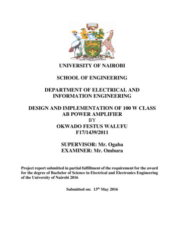
6. Operational amplifiersAs well as resistors and capacitors, Operational Amplifiers, or Op-amps as they are morecommonly called, are one of the basic building blocks of Analogue Electronic Circuits.Operational amplifiers are linear devices that have all the properties required for nearly idealDC amplification and are therefore used extensively in signal conditioning, filtering or toperform mathematical operations such as add, subtract, integration and differentiation.An Operational Amplifier, or op-amp for short, is fundamentally a voltage amplifyingdevice designed to be used with external feedback components such as resistors andcapacitors between its output and input terminals. These feedback components determine theresulting function or “operation” of the amplifier and by virtue of the different feedbackconfigurations whether resistive, capacitive or both, the amplifier can perform a variety ofdifferent operations, giving rise to its name of “Operational Amplifier”.An Operational Amplifier is basically a three-terminal device which consists of two highimpedance inputs, one called the Inverting Input, marked with a negative or “minus” sign,( - ) and the other one called the Non-inverting Input, marked with a positive or “plus” sign( ).The third terminal represents the Operational Amplifiers output port which can both sink andsource either a voltage or a current. In a linear operational amplifier, the output signal is theamplification factor, known as the amplifiers gain ( A ) multiplied by the value of the inputsignal and depending on the nature of these input and output signals, there can be fourdifferent classifications of operational amplifier gain. Voltage – Voltage “in” and Voltage “out”Current – Current “in” and Current “out”Transconductance – Voltage “in” and Current “out”Transresistance – Current “in” and Voltage “out”
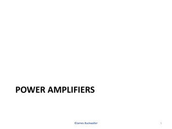
Equivalent Circuit of an Ideal Operational AmplifierOp-amp Parameter and Idealised Characteristic Open Loop Gain, (Avo)o Infinite – The main function of an operational amplifier is to amplify the inputsignal and the more open loop gain it has the better. Open-loop gain is the gainof the op-amp without positive or negative feedback and for such an amplifierthe gain will be infinite but typical real values range from about 20,000 to200,000.Input impedance, (Zin)o Infinite – Input impedance is the ratio of input voltage to input current and isassumed to be infinite to prevent any current flowing from the source supplyinto the amplifiers input circuitry ( Iin 0 ). Real op-amps have input leakagecurrents from a few pico-amps to a few milli-amps.Output impedance, (Zout)o Zero – The output impedance of the ideal operational amplifier is assumed tobe zero acting as a perfect internal voltage source with no internal resistance sothat it can supply as much current as necessary to the load. This internalresistance is effectively in series with the load thereby reducing the outputvoltage available to the load. Real op-amps have output impedances in the 10020kΩ range.Bandwidth, (BW)o Infinite – An ideal operational amplifier has an infinite frequency responseand can amplify any frequency signal from DC to the highest AC frequenciesso it is therefore assumed to have an infinite bandwidth. With real op-amps, thebandwidth is limited by the Gain-Bandwidth product (GB), which is equal tothe frequency where the amplifiers gain becomes unity.Offset Voltage, (Vio)o Zero – The amplifiers output will be zero when the voltage difference betweenthe inverting and the non-inverting inputs is zero, the same or when both inputsare grounded. Real op-amps have some amount of output offset voltage.
Worksheet No.6Exercise 1. Complete the statements with correct words from the text.1. Operational amplifiers are devices that have all the properties required fornearly ideal DC amplification.2. An Operational Amplifier is fundamentally a amplifying device.3. An Operational Amplifier is basically a device.4. Op-amp consists of two high impedance inputs, one called the and the otherone called the .5. The third terminal represents the Operational Amplifiers .Exercise 2. Put the parameters from the box under the correct idealistic characteristic.Avo, Zin, Zout, BW, VioINFINITEZERO
What is the brand of your hi-fi audio, car, guitar, etc. amplifier? 2. SIGNAL A signal as referred to in communication systems, signal processing, and electrical engineering "is a function that conveys information about the behavior or attributes of some phenomenon". In the physical world, a