Transcription
Module1AmplifiersAmplifiers1.0 Introduction to AmplifiersWhat you’ll learn in Module 1Section 1.0 Amplifier Basics. Typical functions of amplifiers in electronicsystems. Graphical representations of amplifiers. Amplifier applications and types of signal.Section 1.1 Amplifier Parameters.Typical amplifier parameters. Gain, Frequency response, Bandwidth, Inputand Output impedance, Phase shift, Feedback.Section 1.2 Class A Biasing. BJT Common emitter and FET common sourcebiasing. Emitter, DC and temperature stabilisation. Class A bias. Common emitter input and outputcharacteristics.An amplifier is used to increase the amplitude of asignal waveform, without changing otherparameters of the waveform such as frequency orwave shape. They are one of the most commonlyused circuits in electronics and perform a variety offunctions in a great many electronic systems.The general symbol for an amplifier is shown inFig 1.0.1. The symbol gives no detail of the type ofamplifier described, but the direction of signal flowcan be assumed (as flowing from left to right of thediagram). Amplifiers of different types are alsooften described in system or block diagrams byname.Section 1.3 Gain and Decibels. Amplification. Logarithmic scales. Specifying voltage and power using dBs. Common dB values.Section 1.4 Bandwidth. Typical Response curves. Factors affecting bandwidth.Section 1.5 Amplifier Basics Quiz. Test your knowledge of AmplifiersAMPLIFIERS 01.PDFFig 1.0.1 Amplifier general symbol, usedin system diagrams1 E. COATES 2007 -2012
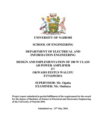
www.learnabout-electronics.orgAmplifiers Module 1For example look at the block diagram of an analogue TV receiver in Fig 1.0.2 and see how manyof the individual stages (shaded green) that make up the TV are amplifiers. Also notice that thenames indicate the type of amplifier used. In some cases the blocks shown are true amplifiers and inothers, the amplifier has extra components to modify the basic amplifier design for a specialpurpose. This method of using relatively simple, individual electronic circuits as "building blocks"to create large complex circuits is common to all electronic systems; even computers andmicroprocessors are made up of millions of logic gates, which are simply specialised types ofamplifiers. Therefore to recognise and understand basic circuits such as amplifiers is an essentialstep in learning about electronics.Fig 1.0.2 Analogue TV receiver block diagram, showing amplifiers used in many stages.One way to describe an amplifier is by the type of signal it is designed to amplify. This usuallyrefers to a band of frequencies that the amplifier will handle, or in some cases, the function that theyperform within an electronic system.A.F. AmplifiersAudio frequency amplifiers are used to amplify signals in the range of human hearing,approximately 20Hz to 20kHz, although some Hi-Fi audio amplifiers extend this range up to around100kHz, whilst other audio amplifiers may restrict the high frequency limit to 15kHz or less.Voltage amplifiers are used to amplify the low level signals from microphones, tape and diskpickups etc. With extra circuitry they also perform functions such as tone correction equalisation ofsignal levels and mixing from different inputs, they generally have high voltage gain and medium tohigh output resistance.Power amplifiers are used to receive the amplified input from a series of voltage amplifiers, andthen provide sufficient power to drive loudspeakers.I.F. AmplifiersIntermediate Frequency amplifiers are tuned amplifiers used in radio, TV and radar. Their purposeis to provide the majority of the voltage amplification of a radio, TV or radar signal, before theaudio or video information carried by the signal is separated (demodulated) from the radio signal.AMPLIFIERS MODULE 01.PDF2 E. COATES 2007 -2021
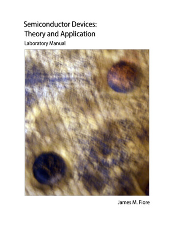
www.learnabout-electronics.orgAmplifiers Module 1They operate at a frequency lower than that of the received radio signal, but higher than the audio orvideo signals eventually produced by the system. The frequency at which I.F. amplifiers operateand the bandwidth of the amplifier depends on the type of equipment. For example, in AM radioreceivers the I.F. amplifiers operate at around 470kHz and their bandwidth is normally 10kHz (465kHz to 475kHz), while TV commonly uses 6Mhz bandwidth for the I.F. signal at around 30 to40MHz, and in radar a band width of 10 MHz may be used.R.F. AmplifiersRadio Frequency amplifiers are tuned amplifiers in which the frequency of operation is governed bya tuned circuit. This circuit may or may not, be adjustable depending on the purpose of theamplifier. Bandwidth also depends on use and may be relatively wide, or narrow. Input resistance isgenerally low, as is gain. (Some RF amplifiers have little or no gain at all but are primarily a bufferbetween a receiving antenna and later circuitry to prevent any high level unwanted signals from thereceiver circuits reaching the antenna, where it could be re-transmitted as interference). A specialfeature of RF amplifiers where they are used in the earliest stages of a receiver is low noiseperformance. It is important that background noise generally produced by any electronic device, iskept to a minimum because the amplifier will be handling very low amplitude signals from theantenna (µV or smaller). For this reason it is common to see low noise FET transistors used in thesestages.Fig. 1.0.3 FM Radio using AF, IF and RF amplifiers.Ultrasonic AmplifiersUltrasonic amplifiers are a type of audio amplifier handling frequencies from around 20kHz up toabout 100kHz; they are usually designed for specific purposes such as ultrasonic cleaning, metalfatigue detection, ultrasound scanning, remote control systems etc. Each type will operate over afairly narrow band of frequencies within the ultrasonic range.Wideband AmplifiersWideband amplifiers must have a constant gain from DC to several tens of MHz. They are used inmeasuring equipment such as oscilloscopes etc. where there is a need to accurately measure signalsover a wide range of frequencies. Because of their extremely wide bandwidth, gain is low.DC AmplifiersDC amplifiers are used to amplify DC (0Hz) voltages or very low frequency signals where the DClevel of the signal is important. They are common in many electrical control systems and measuringinstruments.AMPLIFIERS MODULE 01.PDF3 E. COATES 2007 -2021
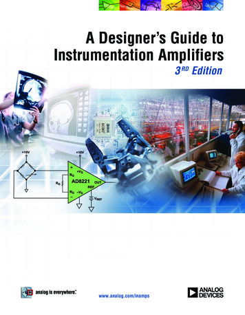
www.learnabout-electronics.orgAmplifiers Module 1Video AmplifiersVideo amplifiers are a special type of wide band amplifier that also preserve the DC level of thesignal and are used specifically for signals that are to be applied to CRTs or other video equipment.The video signal carries all the picture information in TV, video and radar systems. The bandwidthof video amplifiers depends on use. In TV receivers it extends from 0Hz (DC) to 6MHz and iswider still in radar.Buffer AmplifiersBuffer amplifiers are a commonly encountered, specialised amplifier type that can be found withinany of the above categories, they are placed between two other circuits to prevent the operation ofone circuit affecting the operation of the other. (They ISOLATE the circuits from each other). Oftenbuffer amplifiers have a gain of one, i.e. they do not actually amplify, so that their output is thesame amplitude as their input, but buffer amplifiers have a very high input impedance and a lowoutput impedance and can therefore be used as an impedance matching device. This ensures thatsignals are not attenuated between circuits, as happens when a circuit with a high output impedancefeeds a signal directly to another circuit having a low input impedance.Operational AmplifiersOperational amplifiers (Op-amps) have developed from circuits designed for the early analoguecomputers where they were used for mathematical operations such as adding and subtracting. Todaythey are widely used in integrated circuit form where they are available in single or multipleamplifier packages and often incorporated into complex integrated circuits for specific applications.The design is based on a differential amplifier, whichhas two inputs instead of one, and produces an outputthat is proportional to the difference between the twoinputs. Without negative feedback, op amps have anextremely high gain, typically in the hundreds ofthousands. Applying negative feedback increases theop amp’s bandwidth so they can operate as widebandamplifiers with a bandwidth in the MHz range, butreduces their gain. A simple resistor network can applysuch feedback externally and other external networkscan vary the function of op-amps.LM324N Low power Quad Operational Amplifier IC by ST Microelectronics.AMPLIFIERS MODULE 01.PDF4 E. COATES 2007 -2021
www.learnabout-electronics.orgAmplifiers Module 1The Output Properties of AmplifiersAmplifiers are used to increase the amplitude of a voltage or current, or to increase the amount ofpower available usually from an AC signal. Whatever the task, there are three categories ofamplifier that relate to the properties of their output;1. Voltage amplifiers.2. Current amplifiers.3. Power amplifiers.The purpose of a voltage amplifier is to make the amplitude of the output voltage waveform greaterthan that of the input voltage waveform (although the amplitude of the output current may begreater or smaller than that of the input current, this change is less important for the amplifier’sdesigned purpose).The purpose of a current amplifier is to make the amplitude of the output current waveform greaterthan that of the input current waveform (although the amplitude of the output voltage may begreater or smaller than that of the input voltage, this change is less important for the amplifier’sdesigned purpose).In a power amplifier, the product of voltage and current (i.e. power voltage x current) at theoutput is greater than the product of voltage x current at the input. Note that either voltage orcurrent may be less at the output than at the input. It is the product of the two that is significantlyincreased.AMPLIFIERS MODULE 01.PDF5 E. COATES 2007 -2021
www.learnabout-electronics.orgAmplifiers Module 1Module 1.1Amplifier ParametersWhat you’ll learn in Module 1.1.After studying this section, youshould be able to:Describe typical amplifier parameters. Gain. Frequency response.Amplifier ParametersAny amplifier is said to have certain parameters. Theseare the particular properties that make the amplifierperform in a certain way, and so make it suitable for agiven task. Typical amplifier parameters are describedbelow.GainThe gain of an amplifier is a measure of the"Amplification" of an amplifier, i.e. how much itincreases the amplitude of a signal. More precisely it is Input impedance.the ratio of the output signal amplitude to the input Output impedance.signal amplitude, and is given the symbol "A". It can becalculated for voltage (Av), current (Ai) or power (Ap), Phase shift.When the subscript letter after the A is in lower case Feedback.this refers to small signal conditions, and when thesubscript is in capitals it refers to DC conditions. Thegain or amplification for the three differnt types of amplifiers can be described using the appropriateformula: Bandwidth.Voltage gain Av Amplitude of output voltage Amplitude of input voltage.Current gain Ai Amplitude of output current Amplitude of input current.Power gain Ap Signal power out Signal power in.The gain of an amplifier is governed, not only by the components (transistors etc.) used, but also bythe way they are interconnected within the amplifier circuit.Frequency ResponseAmplifiers do not have the same gain at all frequencies. For example, an amplifier designed foraudio frequency amplification will amplify signals with a frequency of less than about 20kHz butwill not amplify signals having higher frequencies. An amplifier designed for radio frequencies willamplify a band of frequencies above about 100kHz but will not amplify the lower frequency audiosignals. In each case the amplifier has a particular frequency response, being a band of frequencieswhere it provides adequate amplification, and excluding frequencies above and below this band,where the amplification is less than adequate.AMPLIFIERS MODULE 01.PDF6 E. COATES 2007 -2021
www.learnabout-electronics.orgAmplifiers Module 1To show how the gain of an amplifier varies with frequency, a graph, showing the frequencyresponse of the amplifier is used. Fig. 1.1.1a shows the typical frequency response curve of an audioamplifier, and Fig. 1.1.1b, that of a RF amplifier. In such graphs, it is common that very largevalues may be encountered for both gain and frequency. For this reason it is usual for both thefrequency and gain axes of the graph to use logarithmic scales. It can be seen from Fig. 1.1.1a thatscales on the (horizontal) x-axis do not increase in a linear manner; each equal division represents atenfold increase in the frequency plotted. This ensures that a very wide range of frequency can beplotted on a single graph. The (vertical) y-axis uses linear divisions but logarithmic units (deciBelsdB). The curve of the graph shows how gain, measured in deciBels, varies with frequency.Fig. 1.1.1a Response curve for an audio amplifierComparing Figs. 1.1.1a and b drawn in this manner, shows how each type of amplifier (audio, RFetc) has its own characteristic shape of frequency response curve. An amplifier which has a verynarrow, sharply peaked response curve is said to be very "selective". This is typical of an RFamplifier and is precisely what is needed in an amplifier designed for the tuning stages of a radiowhere only one radio carrier wave among many hundred others, crowded along the medium waveband for example, must be selected.Fig. 1.1.1b Response curve for a RF amplifier tuned to 774kHzAMPLIFIERS MODULE 01.PDF7 E. COATES 2007 -2021
www.learnabout-electronics.orgAmplifiers Module 1BandwidthAn important piece of information that can be obtained from a frequency response curve is theBandwidth of the amplifier. This refers to the ‘band’ of frequencies for which the amplifier has auseful gain. Outside this useful band the gain of the amplifier is considered to be insufficientcompared with the gain at the centre of the bandwidth. Bandwidth specified for voltage amplifiers isthe range of frequencies for which the amplifier’s gain is greater than 0.707 of the maximum gain(see Fig. 1.1.1.b). Alternatively, decibels are used to indicate the gain, the ratio of output to inputvoltage, (see Fig. 1.1.1.a). The useful bandwidth in Fig. 1.1.1a would be described as extending tothose frequencies at which the voltage gain is 3dB down compared to the gain at the mid bandfrequency. Several ways of describing the bandwidth can be used, firstly it could be said (of Fig1.1.1a), that "The bandwidth is from 10Hz to 20kHz." Alternatively it could be said (of Fig. 1.1.1b)"The bandwidth is 9kHz, centred on 774kHz." or even that it is "774kHz plus or minus 4.5kHz."Input ImpedanceThe word impedance means opposition to AC current flow. At 0 Hz, (that is, DC) impedance(symbol Z) is the same as resistance (R), but at frequencies other than 0Hz impedance andresistance are not the same. The input impedance of an amplifier is the effective impedance betweenthe input terminals. "Effective" means that the impedance is not necessarily just that of the amplifiercomponents (resistors, capacitors etc.) actually connected across the input terminals, but is theimpedance experienced as the amount of current able to flow into the input terminals for a givensignal voltage applied at a particular frequency. Input Impedance is influenced by a number offactors including the frequency of the applied signal, the gain of the amplifier, any signal feedbackused and even what is connected to the output of the amplifier.Output ImpedanceThe output impedance of an amplifier is not solely dependent on the actual components connectedwithin the output of an amplifier. It is an ‘apparent’ impedance and can best be demonstrated asbeing responsible for a fall in signal voltage at the output terminals of an amplifier, when a currentis drawn from the output terminals. The more current drawn from the output terminals, the greaterthe reduction in output signal voltage. The effect is that of an impedance or resistance in series withthe output terminals.Fig. 1.1.2 Amplifier Input and Output ImpedancesAMPLIFIERS MODULE 01.PDF8 E. COATES 2007 -2021
www.learnabout-electronics.orgAmplifiers Module 1Calculation of gain in multi stage amplifiers.Matching of inputs and outputs is necessary to ensure that the maximum amount of signal can betransferred between the amplifier, and any other circuit or device preceding or following it. This isusually the case when the gain of a single amplifier is insufficient for a given purpose. Then severalstages of amplification are used which involves feeding the output of one amplifier into the input ofanother. (This is called connecting the amplifiers in ‘Cascade’). In such designs the outputFig. 1.1.3 Potential divider effect of amplifiers in Cascadeimpedance of the first amplifier and the input impedance of the second amplifier form a potentialdivider, as shown in Fig. 1.1.3When connecting voltage amplifiers in cascade, the input signal to the second stage should ideallybe 100% of the output voltage of stage 1, i.e. have as high a voltage amplitude as possible. This willoccur if the output impedance of the first amplifier is a much lower value than the input impedanceof the second amplifier. This allows most of the voltage available at the output terminal (point A) tobe developed across the input impedance of the second amplifier (and therefore across its inputterminals) rather than across the first amplifier’s output impedance.If the second amplifier is a current amplifier however, it will be necessary that as much current aspossible flows into its input terminals. In this case therefore, the input impedance of the secondamplifier must be low.In the case of power amplifiers, the maximum power is transferred from output to input if bothimpedances are equal.The values of input and output impedance have a considerable effect on the gain of multi stageamplifiers, and there is always some loss of signal amplitude which occurs due to the coupling ofsuccessive amplifier stages. In calculating the overall gain of a multi stage amplifier, the overallgain should be equal to the product of the individual gains of each amplifier. i.e. if each stage of atwo stage amplifier has a gain of 10, then the overall gain should be 10 x 10 100. In practicehowever, this is not achievable due to the coupling losses incurred in matching the amplifiers, and aslightly lower overall gain results.AMPLIFIERS MODULE 01.PDF9 E. COATES 2007 -2021
www.learnabout-electronics.orgAmplifiers Module 1Phase ShiftPhase shift in an amplifier is the amount (if any) by which the output signal is delayed or advancedin phase with respect to the input signal expressed in degrees. If a phase shift of 90 degrees occursthen the peak of the output wave occurs one quarter of a cycle after the peak of input wave. Such ashift can be caused by the effect of components such as resistors inductors and capacitors in theamplifier circuit. The action of the transistor in a single stage amplifier can cause 180 degrees ofphase shift, and therefore the input and output will be in "anti-phase." Whether a phase shift in anamplifier is important depends on the purpose of the amplifier.Fig. 1.1.4 Phase ShiftThe design of multi stage amplifiers must take phase shift into consideration, as the amount ofphase shift will vary with frequency it is possible that at some frequencies the total phase shift mayadd up to 360 degrees. If the output signal of such a system is allowed to re-enter the input thenpositive feedback occurs and the amplifier will become unstable and is likely to oscillate.FeedbackFeedback is the process of taking a proportion of an amplifier’s output signal and feeding it backinto the input. Feedback can be arranged to either increase or decrease the input signal. Whenfeedback is used to increase the input signal it is called POSITIVE FEEDBACK, and when theeffect of the feedback reduces the input signal it is called NEGATIVE FEEDBACK.POSITIVE FEEDBACK occurs when the feedback signal is in phase with the input signal, thisincreases the amplitude of the input and hence the output signal, effectively increasing the gain ofthe amplifier.NEGATIVE FEEDBACK occurs when the feedback signal is in anti-phase with the input signal,effectively reducing the amplitude of the input and hence also the output signal. This causes areduction in gain. See Fig. 1.1.5.Fig. 1.1.5 Negative feedback reduces gain, distortion and noise, it also increases bandwidth.AMPLIFIERS MODULE 01.PDF10 E. COATES 2007 -2021
www.learnabout-electronics.orgAmplifiers Module 1In high quality amplifiers negative feedback is often used to reduce the gain of the amplifier. Aparticular benefit of this, is that any distortion of the signal or background noise produced by theamplifier is also reduced. A further beneficial effect is that applying negative feedback increases thebandwidth of the amplifier. The reason for this can be seen in Fig. 1.1.6 where reducing the heightFig. 1.1.6 The effect of negative feedback on amplifier bandwidth.of the gain curve produces wider spacing of the 0.707 points, therefore widening the bandwidth.AMPLIFIERS MODULE 01.PDF11 E. COATES 2007 -2021
www.learnabout-electronics.orgAmplifiers Module 1Module 1.2Class A BiasingWhat you’ll learn in Module 1.2.An Amplifier’s Common ConnectionAfter studying this section, you should beable to describe:The Reasons for DC Bias in Amplifiers.Advantages and Disadvantages Class A Bias.Simple Common Emitter Fixed DC Bias. The Use of Input Characteristics. Quiescent Conditions. Preventing Distortion with Correct Bias.Transistors in amplifiers commonly use one ofthree basic modes of connection. A transistor hasthree connections (collector, base and emitter),whilst the input and output of an amplifier circuiteach require two connections, making four in total,therefore one of the transistor’s three connectionsmust be common to both input and output. Whethercollector, base or emitter is chosen as beingcommon to both input and output has a markedeffect on how a transistor amplifier operates. Thissection describes how the transistor is biased incommon emitter mode, the most commonly used ofthe three connection modes for voltage amplifiers.Class A Bias Output Characteristics.Class A amplifiers are biased with a DC voltageapplied across the transistor base-emitter junctionso that their quiescent (or no signal) operating pointis on a linear part of the transistor’s characteristics.Also, the signal waveform applied to the baseshould not drive the transistor either into saturationor into cut-off. If this were allowed to happen itwould cause the waveform peaks to be flattened,causing distortion. In class A biasing, the collectorvoltage is kept at approximately half the supplyvoltage, however this means that the transistor ispermanently passing collector current, even whenno signal is applied, so power is being wasted, andalthough class A provides for very low distortion, itis also relatively inefficient in its use of power. Load Line. Basic Fixed Bias Calculations.Bias Stabilisation. Collector Derived Bias. Base Bias networks. Emitter Stabilisation. Use of Emitter Bypass Capacitors.FET Biasing.The theoretical maximum efficiency of a class A amplifier is 50% but in practice the figure wouldbe nearer 25%. The main use for class A bias is in low power audio and radio frequency voltageamplifiers, where the amount of power wasted is less significant than the amplifier’s mainadvantage of low distortion. However class A may also be used for low distortion power amplifiersin mains (line) powered hi-fi audio systems where efficiency is less vital.AMPLIFIERS MODULE 01.PDF12 E. COATES 2007 -2021
www.learnabout-electronics.orgAmplifiers Module 1Common Emitter Fixed BiasingAmplifiers are needed in most pieces of electronic equipment, notonly for sound and picture reproduction but also in control systemsand communications. The design of amplifiers is aimed at producing acircuit that has a predicted gain over a particular band of frequencieswith minimum distortion. The amplifier must also be stable and notprone to oscillation. Bipolar PNP or NPN transistors or FETs may beused in a wide variety of designs depending on their intendedpurpose.Consider the simple bipolar NPN common emitter amplifier shown inFig. 1.2.1 consisting of a transistor and two resistors. To functioncorrectly the amplifier should produce at its output, an amplifiedversion of the signal at its input without distortion. In order to do this,its quiescent or no signal (DC) conditions, must first be correct. Itsoutput can only be undistorted if its input is undistorted.Fig 1.2.1 Simple bias for acommon emitter amplifier.Using the Input Characteristics.Fig. 1.2.2 shows a typical input characteristic curvefor a small signal amplifier transistor where changesin base voltage Vb are plotted against the resultingchanges in base current Ib.If changes in the AC signal voltage (changes in Vb)applied to the base, are to produce proportionalchanges in AC base current Ib then some DC value ofVB must be used so that positive and negativeexcursions of the signal voltage occur only on thelinear part of the input curve (waveform b in Fig.1.2.2). This DC voltage (0.7V in Fig. 1.2.2) appliedto the base is called the base bias voltage. It can beseen from Fig. 1.2.2 that if the bias voltage isinsufficient, then only the positive tips of the inputvoltage waveform would produce base current, andconsequently severe distortion will occur in the basecurrent waveform a.Fig. 1.2.2 Input Characteristics.It can also be seen that for this transistor, a DC base bias voltage (RB) of 0.7V produces a quiescent(DC) base current of 40µA. These values are set by the correct choice of resistance value for RB(Fig. 1.2.1).Setting the Quiescent Output ConditionsThe quiescent output conditions must also be considered, as the quiescent base current Ib willproduce a quiescent collector current Ic that will depend on the value of Ib and the current gain hfe ofthe transistor. Also, because Ic flows through the load resistor (RL) it will produce a potentialdifference across RL that when subtracted from the supply voltage (Vcc) gives the value of thetransistor collector/emitter voltage (Vce).AMPLIFIERS MODULE 01.PDF13 E. COATES 2007 -2021
www.learnabout-electronics.orgAmplifiers Module 1Fig. 1.2.3 Incorrect Bias ConditionsFig. 1.2.3 shows the two extreme conditions for the values of Ic and Vce. It can be seen in the firstcase (Fig. 1.2.3a), that if the collector current IC is zero, owing to the base voltage being lowenough to cut off base current, the voltage developed across RL will be zero and the whole of Vccwill be developed across the transistor so Vce will rise to the supply voltage Vcc.If a signal is applied under these conditions (Fig. 1.2.3a), positive going half cycles of the outputsignal (which is in anti phase to the voltage waveform at the base) cannot make Vce rise any furtherthan Vcc and so the positive going half cycles of collector voltage will not be reproduced, causingsevere distortion.Alternatively if Ic is very high (Fig 1.2.3b) due to excessive base bias, the transistor will be in asaturated condition and Vce will fall to almost zero. As the collector voltage cannot fall below 0Vthe negative going half cycles of the output signal will be lost. It follows therefore, that to reproducethe full waveform at the collector, the ideal quiescent value for Vce will be around midway betweenVcc and zero volts. This will allow the maximum amplitudes of both positive and negative goinghalf cycles of the output wave to be reproduced without distortion.Using the Output CharacteristicsIn the output characteristics shown in Fig.1.2.4 changes in Ic are plotted againstchanges in Vce for various constant basecurrents Ib .A load line is drawn on Fig. 1.2.4between the two extreme points describedin Fig. 1.2.3.Point P is where VCE Vcc (which in thiscase equals 10V) and Ic zero, andbecause no current collector is flowing,the transistor is said to be "Cut off".Point R is the maximum value of Ic (whereIc Vcc RL) and Vce is zero (becausepractically the whole of Vcc is developedFig. 1.2.4 Output Characteristics and Load Lineacross RL). This is called "Saturation" asno further increase in collector current will occur.With the load line drawn from P to R, it can be seen that a value of Vce can be chosen mid-wayalong the load line at point Q, which in this case coincides with the curve for IB.AMPLIFIERS MODULE 01.PDF14 E. COATES 2007 -2021
www.learnabout-electronics.orgAmplifiers Module 1A vertical line projected downwards from Q then intersects the VCE axis midway between Vcc andzero, and a horizontal line projected from Q intersects the IC axis to give a quiescent value of 8mA.From the values of VCce and IC indicated, it is now possible to calculate a value for RL using:RL (Vcc - Vce ) IcSo using the load line at point Q (or any other point with different pairs of values):RL (10 5) 8 x10 3 625ΩBiasing an amplifier so that the operating point is at the centre of the linear part of the transistor’scharacteristic curves is called Class A bias .Example:Design the DC fixed bias conditions for the simple class A common emitter amplifier shown in Fig.1.2.1, assuming a supply voltage (Vcc ) of 10V using a transistor with a common emitter currentgain (hfe) of 200.From the input characteristics (Fig. 1.2.3) Ib needs to be 40µA, which indicates a value for Vbe of0.7V.Therefore:Rb ( Vcc - Vbe) Ib (10 0.7) 40µA 232.5KΩBecause, in a practical circuit,
Audio frequency amplifiers are used to amplify signals in the range of human hearing, approximately 20Hz to 20kHz, although some Hi-Fi audio amplifiers extend this range up to around 100kHz, whilst other audio