Transcription
5. CMOS Operational AmplifiersAnalog Design for CMOS VLSI SystemsFranco Maloberti
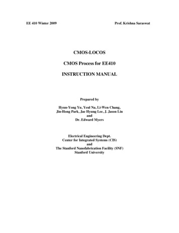
Basic op-ampThe ideal operational amplifier is a voltage controlledvoltage source with infinite gain, infinite input impedanceand zero output impedance.The op-amp is always used in feedback configuration.Analog Design for CMOS VLSI SystemsFranco Maloberti5. CMOS Operational Amplifiers1
Typical feedback configurationZ4 Z1 Z2Z2V0 V2 V1Z3 Z4 Z1Z1Finite gain effect: Z4 Z1 Z2Z2 Z1 Z2 V0 V2 V1 1 Z1 A0Z1 Z3 Z4 Z1The error due to the finite gain is proportional to 1 / A0. Thiserror must be smaller than the error due to impedancemismatch.Analog Design for CMOS VLSI SystemsFranco Maloberti5. CMOS Operational Amplifiers2
OTAIf impedances are implemented with capacitors andswitches, after a transient, the load of the op-amp is madeof pure capacitors. The behavior of the circuit does notdepend on the output resistance of the op-amp and stageswith high output resistance (operational transconductanceamplifiers) can be used.Analog Design for CMOS VLSI SystemsFranco Maloberti5. CMOS Operational Amplifiers3
TransientC1Vi (0 ) VinC1 C // C0 CVo (0 ) Vi (0 )C0 C C1 CVi ( ) VinC1 C(1 gm r0 )Vo ( ) Vi ( ) gm r0C0 gmAnalog Design for CMOS VLSI SystemsFranco Maloberti5. CMOS Operational Amplifiers4
Performance characteristicsActual op-amps deviate from the ideal behavior. Thedifferences are described by the performancecharacteristics.DC differential gain:It is the open-loop voltage gain measured at DC with asmall differential input signal. Typically Ad 80 100 dB.Analog Design for CMOS VLSI SystemsFranco Maloberti5. CMOS Operational Amplifiers5
Common mode gain:It is the open-loop voltage gain with a small signal appliedto both the input terminals. Acm 20 40 dB.Common mode rejection ratio:It is defined as the ratio between the differential gain andthe common mode gain. Typically CMRR 40 80 dB.Analog Design for CMOS VLSI SystemsFranco Maloberti5. CMOS Operational Amplifiers6
Power supply rejection ratio:If a small signal is applied in series with the positive (ornegative) power supply, it is transferred to the output with agiven gain Aps (or Aps-).The ratios between differential gain and power supply gainsfurnish the two PSRRs.Typically:PSRR 90 dB (DC)PSRR 60 dB (1 kHz)PSRR 30 dB (100 kHz)Analog Design for CMOS VLSI SystemsFranco Maloberti5. CMOS Operational Amplifiers7
Input offset voltage:In real circuits if the two input terminals are set at the samevoltage the output saturates close to VDD or to VSS.Typically Vos 4 6 mV.Input common mode range:It is the maximum range of the common-mode input voltagewhich do not produce a significant variation of thedifferential gain.Analog Design for CMOS VLSI SystemsFranco Maloberti5. CMOS Operational Amplifiers8
Output voltage swing:It is the swing of the output node without generating adefined amount of harmonic distortion.Equivalent input noise:The noise performances can be described in terms of anequivalent voltage source at the input of the op-amp.Typically vn 40 50 nV/ Hz at 1 kHz,in a wide band (1 MHz) it results 10 50 V RMS.Analog Design for CMOS VLSI SystemsFranco Maloberti5. CMOS Operational Amplifiers9
Unity gain frequency:It is the frequency where the open-loop gain is zero. It isalso the -3 dB bandwidth in unity-gain closed loopconditions. Typically fT 200 MHz.Phase margin:It is the phase shift of the small-signal differential gainmeasured at the unity gain frequency. A phase marginsmaller than 60 causes ringing in the output response.Analog Design for CMOS VLSI SystemsFranco Maloberti5. CMOS Operational Amplifiers10
Slew rate:It is the maximum slope of the output voltage. Usually it ismeasured in the buffer configuration. The positive slew ratecan be different from the negative slew rate. Typically SR 50 200 V/ s (lower values for micropower operation).Settling time:The settling time is the time required to settle the outputwithin a given range (usually 0.1%) of the final value.Power dissipation:It depends on speed and bandwidth requirements.Typically, for 3.3 V supply, it is around 1 mW.Analog Design for CMOS VLSI SystemsFranco Maloberti5. CMOS Operational Amplifiers11
Typical parameters of a 0.25 m OTAFeatureDC gainCMRROffsetBandwidthSlew-rateSettling time: 1 V, CL 4 pFPSRR @ DCPSRR @ 1 kHzPSRR @ 100 kHzInput referred noise (white)Corner frequencySupply voltageInput common mode voltageOutput dynamic rangePower consumptionSilicon areaAnalog Design for CMOS VLSI SystemsFranco 00UnitdBdBmVMHzV/ snsdBdBdBnV/ HzkHzVVVppmW m25. CMOS Operational Amplifiers12
Basic architecture 1st gain stage differential to single-ended converter 2nd gain stage output stage (to reduce the output impedance)Key requirements: absolute stability in unity gain closed-loop conditionswhen driving maximum load. minimum number of gain stages.Analog Design for CMOS VLSI SystemsFranco Maloberti5. CMOS Operational Amplifiers13
Two-stage op-ampKey design issues: open-loop differential gain dc offset power supply rejection (PSRR)Analog Design for CMOS VLSI SystemsFranco Maloberti5. CMOS Operational Amplifiers14
Open-loop differential gain:The gain is obtained by multiplying the gains of the twostages.gm1gm5Av A1A2 (gds2 gds 4 ) (gds5 gds6 ) 2 2µn µp Cox( n p )2 W W W L 1 L 5 L B 1IBias W W L 6 L 7At low frequency the gain is inversely proportional to thebias current.Analog Design for CMOS VLSI SystemsFranco Maloberti5. CMOS Operational Amplifiers15
Common mode dc gain:Applying the same signal to both inputs the circuit becomessymmetrical and can be studied considering half circuit.ACM ACM1ACM2 g g ds7m5 2gm1 gds5 gds6 Av2gm1gm3CMRR ACM gds7 (gds2 gds 4 )Analog Design for CMOS VLSI SystemsFranco Maloberti5. CMOS Operational Amplifiers16
Offset:The offset is composed of two terms: systematic offset random offsetThe systematic offset can be reduced to zero with acareful design. A necessary condition to have zerosystematic offset, is that the currents of M5 and M6 areequal, when the inputs are connected to the same voltage.Assuming all the transistors in saturation this condition is:W L)W L) (W L)(( II(W L)(W L) (W L)1(W L) (W L) 2 (W L) (W L)6BiasBiasB3Analog Design for CMOS VLSI SystemsFranco Maloberti675B3755. CMOS Operational Amplifiers17
The random offset is due to the geometrical mismatchingand process dependent inaccuracies.When we refer the offset of the second stage at the inputterminal we have to divide it by the gain of the first stage.Since the two offsets are uncorrelated we have:2 Vos22Vos Vos1 A1 The total offset is dominated by the offset of the inputstage.Analog Design for CMOS VLSI SystemsFranco Maloberti5. CMOS Operational Amplifiers18
We study the effect of a mismatch between M3 and M4:mirror factor (1 ) instead of 1. I IVos1 Vos1 BiasBias gm1 gm2 1 2 2 2 2()Analog Design for CMOS VLSI SystemsFranco MalobertiVos1I1 gm15. CMOS Operational Amplifiers19
MOS:VGS1 VThI1 150 300 mVgm12(in saturation)I1nkT nVT qgm1(in sub-threshold)BJT:I1 26 mVgm1Assuming 0.01:Vos,BJT 0.26 mVVos,MOS 1.5 3 mVAnalog Design for CMOS VLSI SystemsFranco Maloberti5. CMOS Operational Amplifiers20
Power supply rejection:A signal on the positive bias line determines a modulationin the reference current, which, in turn, gives an equalmodulation of the currents in M5 and M6, if the condition ofthe zero systematic offset is fulfilled.Analog Design for CMOS VLSI SystemsFranco Maloberti5. CMOS Operational Amplifiers21
The spur signal v n affects the currents of M5 and M6.in,7in,6 µCox VGS,MB VTh vn W /LW /L() ()6()7a) low frequency: W /L W/LW/L11657 vo,n,1 in,tot 2 W / L W / L gds6 gds7 W / LB4B(())(()()())b) high frequency:vo,n,1 in,Ref(W / L)(W / L)6BAnalog Design for CMOS VLSI SystemsFranco Maloberti1gm55. CMOS Operational Amplifiers22
Power supply rejection at low frequency(v )o,tot2 gm5 (1 k ) gds6 2gm3 rds3 vn gds5 gds6 Analog Design for CMOS VLSI SystemsFranco Maloberti( ) gm5k gds6 22gm3 rds3 vn gds5 gds6 ( )25. CMOS Operational Amplifiers23
Effect of external components on PSRRAnalog Design for CMOS VLSI SystemsFranco Maloberti5. CMOS Operational Amplifiers24
Frequency response andcompensation A two-stage scheme with poles in the same frequencyrange needs compensation. A single pole system is always stable. Strategy: Approach the single pole performance bysplitting the two poles apart.Analog Design for CMOS VLSI SystemsFranco Maloberti5. CMOS Operational Amplifiers25
Miller capacitance moves p1 at lower frequency.Shunt feedback moves p2 at higher frequency.Small signal equivalent circuit for two-stage op-amp.v1(g1 sC1) (v1 v0 )sCc gm1vin 0v0 (g2 sC2 ) (v0 v1)sCc gm2v1 0v0gm2 sCc gm1R1R2vin1 sR1R2gm2Cc s 2R1R2 C1C2 (C1 C2 )Cc[Analog Design for CMOS VLSI SystemsFranco Maloberti]5. CMOS Operational Amplifiers26
The circuit has two poles and a zero in the right half plane. 1p1 R1R2gm2Cc gm2Ccp2 C1C2 (C1 C2 )Ccgm2z Ccsince in practice Cc C1, Cc C2, gm1 1/R1, gm2 1/R2 itresults:1p1 R1C1gm21p2 R2C2C2Assuming p1 as dominant, the unity gain angular frequencyis:1gm1 T p1 A0 gm1gm2R1R2 R1R2gm2CcCcAnalog Design for CMOS VLSI SystemsFranco Maloberti5. CMOS Operational Amplifiers27
The locations of the second pole p2 and of the zero withrespect to T are derived by considering:p2gm2Cc Tgm1C2zgm2 Tgm1Analog Design for CMOS VLSI SystemsFranco Malobertifor stability 2 to 4The phase shift given by thezero is also negative andcan worsen the phasemargin. It must be locatedfar from the unity gainfrequency.5. CMOS Operational Amplifiers28
if Cc C2 and gm2 gm1 The right half-plane worsen the phase margin. In bipolar technology gm2 gm1 because the current inthe second stage is normally higher than the one in thefirst stage.Analog Design for CMOS VLSI SystemsFranco Maloberti5. CMOS Operational Amplifiers29
In CMOS technology gm2 gm1 because they areproportional to the square root of I and W/L; moreover,the transconductance of the input pair must be high inorder to reduce their thermal noise contribution. In real situations the obtainable phase margin does notguarantee stability.Eliminating the right half-plane zero: unity gain buffer zero nulling resistor unity gain current amplifierThe zero is due to a signal feedforwardto a point that is 180 out of phase.Analog Design for CMOS VLSI SystemsFranco Maloberti5. CMOS Operational Amplifiers30
Solution 1: Eliminate feedforward with source followerDisadvantages: Area Power dissipation Actually it creates a doublet in the feedback path.Potentially not stable. Alternative, a substrate emitter follower may be used.(The bipolar transistor is smaller and has higher gm.)Analog Design for CMOS VLSI SystemsFranco Maloberti5. CMOS Operational Amplifiers31
Solution 2: Zero nulling resistorThe zero position is pushed away with a resistance inseries with Cc.()1 s Rz 1/ gm2 Ccv0 A0 vins s 1 1 p1 p2 Analog Design for CMOS VLSI SystemsFranco Maloberti5. CMOS Operational Amplifiers32
The pole locations are close to the original. The zero is moved depending on Rz.1z 1/ gm2 Rz Cc() If Rz 1 / gm2 the zero is moved at infinity If Rz 1 / gm2 the zero is located in the left half-planeImplementation:111 Rz Rn RpAnalog Design for CMOS VLSI SystemsFranco Maloberti5. CMOS Operational Amplifiers33
W 1 kn VDD V1 VTh,nRn L n() W 1 kp V1 VSS VTh,pRp L p()Choose (W/L)n and (W/L)p such that: W W kn kp L n L pand: W 1 kn VDD Vss VTh,n VTh,pRz L nProblem: Supply sensitivity.Since the swing of the node 1 is A2 less than the outputswing, only one transistor with supply independent bias canbe used.(Analog Design for CMOS VLSI SystemsFranco Maloberti)5. CMOS Operational Amplifiers34
Solution 3: Unity gain current amplifierv1(g1 sC1) gm1vin v0sCc 0v0 (g2 sC2 ) gm2v1 v0sCc 0Analog Design for CMOS VLSI SystemsFranco Maloberti5. CMOS Operational Amplifiers35
Slew rateFor large input signal: M1, M4 are off so the current IM7 discharges Cc throughM2. Assuming M5 able to drive the current request by Cc,CL and IM6. V IM7SR t maxCcAnalog Design for CMOS VLSI SystemsFranco Maloberti5. CMOS Operational Amplifiers36
M2, M5 are off so the current IM7 mirrored by M4 chargesCc; CL and Cc are charged by IM6. The smaller of thesetwo limits will hold: V IM7 V IM6SR SR t max Cc tC CmaxcLTo have SR SR-, a condition can be:IM6IM7 Cc Cc CLSince T gm1 / Cc, the SR isIM7SR T VGS1 VTh Tgm1For T 2 · 40 · 106 rad/s, (VGS1 - VTh) 300 mV, SR 75.4 V/ s.(Analog Design for CMOS VLSI SystemsFranco Maloberti)5. CMOS Operational Amplifiers37
Single stage schemesHigh gain is get with a cascode scheme. Telescopic cascode Mirrored cascode Folded cascodeAnalog Design for CMOS VLSI SystemsFranco Maloberti5. CMOS Operational Amplifiers38
Telescopic cascode DC gain A0 (gmrds)2 low power consumption only one high impedancenode: compensated with acapacitance load (ifnecessary) low output swing reference of the input closeto the negative supply two bias lines (VB1, VB2) 5 transistors in seriesAnalog Design for CMOS VLSI SystemsFranco Maloberti5. CMOS Operational Amplifiers39
Mirrored cascode optimum input commonmode range only 4 transistors in series improved output swing speed of the mirror higher power consumptionVoutmax VB1max VGS4 - VsatVB1max VDD - Vsat - VGS4Voutmax VDD - 2VsatVoutmax VGS7 VsatAnalog Design for CMOS VLSI SystemsFranco Maloberti5. CMOS Operational Amplifiers40
Conventional folded cascodeAnalog Design for CMOS VLSI SystemsFranco Maloberti5. CMOS Operational Amplifiers41
Modified folded cascode(improved output swing)Analog Design for CMOS VLSI SystemsFranco Maloberti5. CMOS Operational Amplifiers42
Two stage amplifier vs. single stage amplifierTwo stages: Voltage gain less affected by resistive loading Maximum signal swing Less bussing of bias lines Requires an additional capacitor for frequencycompensation More power consumptionAnalog Design for CMOS VLSI SystemsFranco Maloberti5. CMOS Operational Amplifiers43
Single stage: No need for additional compensation capacitor Lower power consumption Better CMRR Lower signal swing More bussing of bias linesAnalog Design for CMOS VLSI SystemsFranco Maloberti5. CMOS Operational Amplifiers44
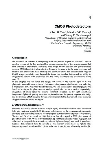
Class AB op-ampsClass AB: a circuit which can have an output current whichis larger than its DC quiescent current.Two stages amplifier with class AB second stageM6 and M7 act as alevel shifterM8 and M9 act as aclass AB push-pullamplifiergm8 gm9A2 gds8 gds9Analog Design for CMOS VLSI SystemsFranco Maloberti5. CMOS Operational Amplifiers45
The quiescent current in the output stage is bias voltageand technological variation dependent.VDD VGS8 VGS6 VGS9neglecting the body effect:VDD VTh,p 2VTh,n2 L 2 L 2 L I6 I8 I9kn W 6kn W 8kn W 9VDD VTh,p 2VTh,nI9 2 L I6kn W 62 L 2 L kn W 9kn W 8Typically with VDD 5 V the numerator is around 1.6 V; if itis assumed VDD (5 0.5) V and VTh 200 mV, itresults that the numerator can change from 0.7 V to 2.5 V;hence, Imin 0.3 Inom; Imax 2.5 InomAnalog Design for CMOS VLSI SystemsFranco Maloberti5. CMOS Operational Amplifiers46
Single stage class AB amplifier (only inverting)In the input pair M1 and M2operate as source followersand drive the common gatestage M3 and M4.VB VTh,n VTh,p Vov,n Vov,pfor Vin 0I1 I2 IBiasfor Vin 0Iout K8,9 I1 - K5,6 I2K8,9 and K5,6 mirror factors(assumed equal)Analog Design for CMOS VLSI SystemsFranco Maloberti5. CMOS Operational Amplifiers47
VB Vin VGS2 VGS 4 VTh,n VTh,p 2 W2 W I2 kn L Lk p24 VB Vin VGS1 VGS3 VTh,n VTh,p 2 W2 W I1 kn L Lk p31 It results:Iout K8,9 (I1 - I2) K8,9 VB VinUntil I1 or I2 goes to zero, for alarger Vin, Iout increasesquadratically with Vin.Small signal gain:Av 2 Gm routAnalog Design for CMOS VLSI SystemsFranco Maloberti5. CMOS Operational Amplifiers48
Gm is the transconductance of the cross coupled inputstage()gm2 Vin VA gm4VAgm2VinVA gm2 gm4Ioutgm2gm4 gm4VA Vin GmVingm2 gm4Analog Design for CMOS VLSI SystemsFranco Maloberti5. CMOS Operational Amplifiers49
Fully differential op-ampsThe use of fully differential paths in analog signalprocessing gives benefits on: PSRR dynamic range clock feedthrough cancellationConsider an integrator and its fully differential version:Analog Design for CMOS VLSI SystemsFranco Maloberti5. CMOS Operational Amplifiers50
Noise from the power supply and clock feedthrough arecommon mode signals. The output swing is doubled (Vmax - Vmax- 2 Vmax).Since the noise is unchanged, the dynamic rangeimproves by 6 dB. Single ended to differential and double ended to singleended converters are necessary Larger area More bussing of bias lines Common mode feedback is necessaryAnalog Design for CMOS VLSI SystemsFranco Maloberti5. CMOS Operational Amplifiers51
The SE/DE and DE/SE blocks increase the complexity andintroduce noise. The differential approach is convenient ifthe differential processor contains more than 4 stages.The feedback around the op-amp control the difference ofthe input terminal voltages and not their mean value. In turn,there is no control on the output common mode voltage.Analog Design for CMOS VLSI SystemsFranco Maloberti5. CMOS Operational Amplifiers52
Fully differential two stage OTA1st stage with gain:1gm1A1 2 gds1 gds 4Analog Design for CMOS VLSI SystemsFranco Malobertitwo 2nd stages with gain:gm5A2 gds5 gds65. CMOS Operational Amplifiers53
Fully differential single stage OTAAnalog Design for CMOS VLSI SystemsFranco Maloberti5. CMOS Operational Amplifiers54
COMMON MODE FEEDBACK continuous time sampled dataContinuous-time common mode feedbackAnalog Design for CMOS VLSI SystemsFranco Maloberti5. CMOS Operational Amplifiers55
VB is such that M1 and M2 are in the linear region;(W/L)1 (W/L)2; M1 and M2 are like the parallel of twovoltage dependent resistances. W 1 2 I1 µCoxV VTh VDS VDS2 L 1 W 1 2 I2 µCoxV VTh VDS VDS2 L 2 W 21Iout I1 I2 µCox VB VDS VTh2 L 3()()()With a differential signal Iout costWith a common mode signal: if positive, Iout increasesif negative, Iout decreasesAnalog Design for CMOS VLSI SystemsFranco Maloberti5. CMOS Operational Amplifiers56
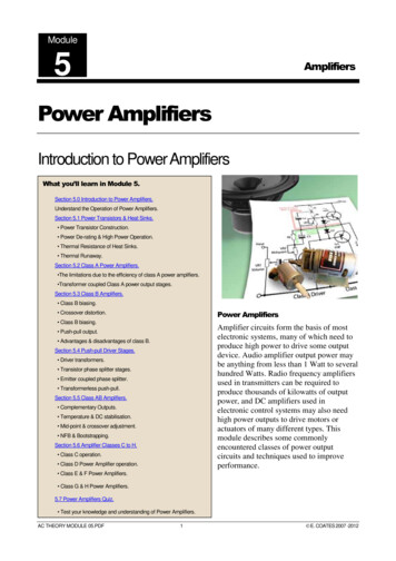
Fully differential folded cascode with CMFBAnalog Design for CMOS VLSI SystemsFranco Maloberti5. CMOS Operational Amplifiers57
Fully differential folded cascode with CMFB (2)Analog Design for CMOS VLSI SystemsFranco Maloberti5. CMOS Operational Amplifiers58
Problems: dynamic range linearityCompensation of the non-linearities of the n-channel and pchannel CMFB cell.Analog Design for CMOS VLSI SystemsFranco Maloberti5. CMOS Operational Amplifiers59
Sampled-data common mode feedbackThe common mode feedback operates on slowly variablesignal. It can be implemented at discrete time intervals.The sampled data feedback is essential for low biasvoltage and low power. linearity (mean value withcapacitors) low power consumption no limitation to the dynamicrange clock signal necessary clock feedthrough effectAnalog Design for CMOS VLSI SystemsFranco Maloberti5. CMOS Operational Amplifiers60
Micro-power op-amps Required in battery operated systems(portable/wearable equipment: pocket calculators, PDA's, digitalcameras, ; medical equipment: pace makers, hearing aids, ); Use of MOS transistors in weak inversion; Low current ( 10 A) low slew rate.IDgm nVTgds IDB gm1B Av gds6 gds8 nVT n p()high dc gain (Av 60 dB)Analog Design for CMOS VLSI SystemsFranco Maloberti5. CMOS Operational Amplifiers61
Dynamic biasing of the tail currentBasic idea:Generate I1 - I2 and increase the current in the differentialstage by k I1 - I2 .Analog Design for CMOS VLSI SystemsFranco Maloberti5. CMOS Operational Amplifiers62
SinceIDgm nVTi1 i2 gm (vin vin )(i1 i2 IB k i1 i2ID IB k i1 i2)vin vin nVTThe current increase becomes significant when:vin vin k 1nVTTypical performance:DC gain95 dBft130 kHzSR0.1 V/ s0.5 AIBItot2.5 AAnalog Design for CMOS VLSI SystemsFranco Maloberti5. CMOS Operational Amplifiers63
Class AB single stage with dynamic biasingFor maximum output swing VBIAS-p and VBIAS-n must be asclose as possible to the supply voltages.Analog Design for CMOS VLSI SystemsFranco Maloberti5. CMOS Operational Amplifiers64
During the slewing the current source of the outputcascodes can be pushed in the linear region, hence loosingthe advantage of the AB operation.The problem is solved with the dynamic biasing:Analog Design for CMOS VLSI SystemsFranco Maloberti5. CMOS Operational Amplifiers65
Noise The noise of an operational amplifier is described with aninput referred voltage source vn. The spectrum of vn is made of a white term and 1/f term. vn is due to the contributions, referred to the input, of thenoise generators associated to all the transistors of thecircuit (assumed uncorrelated).Analog Design for CMOS VLSI SystemsFranco Maloberti5. CMOS Operational Amplifiers66
Consider the input stage of a two stage op-amp.The output noise voltage is given by:2vn,out2 1222222 gm1(vn1 vn2 ) gm3 (vn3 vn 4 ) gds2 gds 4 [Analog Design for CMOS VLSI SystemsFranco Maloberti]5. CMOS Operational Amplifiers67
We assume gm1 gm2; gm3 gm4 (we assume the noisesource of M5 does not contribute) moreover since usuallyW1 W2; L1 L2; W3 W4; L3 L4; v2n1 v2n2; v2n3 v2n4;if we refer v2n,out to the input, we get:2vn,out21A2 vn,in 2vn,out2m1g(gds2 gds 4)22 g2m3 2 2 vn1 2 vn3 gm1 The contribution of the active loads is reduced by thesquare of the ratio gm3/gm1It is worth to remember thatWgm 2µCoxILAnalog Design for CMOS VLSI SystemsFranco Maloberti 8kT1 1 KFv f 3gm 2µCox WL f 2n5. CMOS Operational Amplifiers68
The attenuation by the factor (gm3/gm1)2 gives, for the whiteterm: µW/L 3gm3222 3 2v1 vn,in,w 2vn1 1 n1 gµ1 W / L m1 1 and for the 1/f term: K L2 1K2F1vn,in,1/ 1 F 3 21 f 2µ1CoxW1L1 f KF1L3 (())Where KF1 and KF3 are the flicker noise coefficient fortransistors M1 and M3. The white contribution of the activeload is reduced by choosing (W/L)input (W/L)load. The 1/fnoise contribution of the active load is reduced by choosingLinput Lload. If the above conditions are satisfied the inputnoise is dominated by the input pair.Analog Design for CMOS VLSI SystemsFranco Maloberti5. CMOS Operational Amplifiers69
Cascode scheme:The noise is contributed bythe input pair and the currentsources of the cascode load.2vn,in2 gm42 2 vn1 vn24 gm1 Analog Design for CMOS VLSI SystemsFranco Maloberti5. CMOS Operational Amplifiers70
Folded cascode scheme:The noise contributed by the same source as in thecascode and by the current source M2.22 gg2222vn,in 2 vn1 m2 vn2 m5 vn5 gm1 gm1 Analog Design for CMOS VLSI SystemsFranco Maloberti5. CMOS Operational Amplifiers71
Two stage op-amp: (feedforward zero nulling comp.)The noise is modeled with two input referred noise sources:one at the input of the first stage and the other at the inputof the second stage.Analog Design for CMOS VLSI SystemsFranco Maloberti5. CMOS Operational Amplifiers72
In the low frequency range the noise is dominated by vn1.In the high frequency range the noise is dominated by vn2.Analog Design for CMOS VLSI SystemsFranco Maloberti5. CMOS Operational Amplifiers73
Frequency response:The input referred noise generator is transmitted to theoutput as a conventional input signalThe feedback network around the op-amp must be takeninto account.One stage amplifier:The cutoff frequency is: p1 -gm/C0Analog Design for CMOS VLSI SystemsFranco Maloberti5. CMOS Operational Amplifiers74
Power of noise:We consider only the white term. Single stage amplifier:v2n0df8 v 2 1 kT31 s / p10 (2n) 01dfgm1 1 2 fC / g0m1()28kT 1 3C0() Two stage amplifier: we consider only the white termcontributed by the noise source of the second stagev2n28 kT 2 1 3 gm2(p2 v)gm2C1 C2Analog Design for CMOS VLSI SystemsFranco Maloberti2n0 v0 2vn0 2n2df1 s / p2kT41 C1 C23()5. CMOS Operational Amplifiers75
LayoutRules: Use poly connections only for voltage signals, never forcurrents, because the offset RI 15 mV. Minimize the line length, especially for lines connectinghigh impedance nodes. Use matched structure (necessary common centroid). Respect symmetries (even respect power devices). Only straight-line transistors. Separate (or shield) the input from the output line, toavoid feedback. Shield high impedance nodes to avoid noise injectionfrom the power supply and the substrate. Regular shapes and layout oriented design.Analog Design for CMOS VLSI SystemsFranco Maloberti5. CMOS Operational Amplifiers76
Stacked layout:Csb Cdb CjbW (d 2x j )Structure A:1WCsb Cdb Cjb(d 2x j )22Structure B:2WCsb Cdb Cjb(d 2x j )3Capacitances arefurther reduced if thediffusion area is sharedbetween differenttransistors.Analog Design for CMOS VLSI SystemsFranco Maloberti5. CMOS Operational Amplifiers77
Key point: use of equal width transistorsTransistors with arbitrary width are not allowed.Placement and routing: If we divide a transistor inan odd number of paralleltransistors the resultingstack has the source onone side and the drain onthe other side.Analog Design for CMOS VLSI SystemsFranco Maloberti If we divide a transistor inan even number of partsthe resulting stack hassource or drain on the twosides.5. CMOS Operational Amplifiers78
Example:Routing into stacks: use of comb connections or serpentineconnections.Analog Design for CMOS VLSI SystemsFranco Maloberti5. CMOS Operational Amplifiers79
Analog Design for CMOS VLSI SystemsFranco Maloberti5. CMOS Operational Amplifiers80
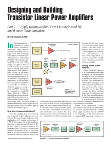
Example: Fully differential folded cascode.Analog Design for CMOS VLSI SystemsFranco Maloberti5. CMOS Operational Amplifiers81
Analog Design for CMOS VLSI SystemsFranco Maloberti5. CMOS Operational Amplifiers82
5. CMOS Operational Amplifiers 1 Analog Design for CMOS VLSI Systems Franco Maloberti Basic op-amp The ideal operational amplifier is a voltage controlled voltage source with infinite gain, infinite input impedance and zero output impeda