Transcription
POWER AMPLIFIERS James Buckwalter1
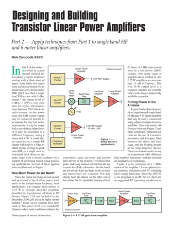
Power Amplifiers Purpose of a power amplifier– Generate high output power– Efficient conversion of DC power to RFpower– Linear amplification Generally PAs will be– Common source– Cascode Inductor is a “choke” to provide DC Capacitor is a “ac coupling” path tooutput James Buckwalter2
Definition of Power Instantaneous Power Average PowerP v (t ) i (t )T1Pav ò v (t ) i (t ) dtT t 0 There is a component that averages to zero thatcorresponds to energy stored and dissipated eachcycle. James Buckwalter3
Definition of Power If the voltage and current isv ( t ) V cos (wt )i (t ) I cos (wt q ) The average power becomesT112Pav VI cosq ò cos (wt ) dt VI cosqT2t 0 In phasor notation v (t ) V Re {e jwt }11 21 21*P Re {vi } V Re {Y } I Re { Z } Preac Im { vi * }2222 James Buckwalter4
Example: James Buckwalter5
Time Scales for Power Amplifiers Carrier T 1ns, Period Ts 100ns, Control 1ms James Buckwalter6
Power Scales for Power Amplifiers James Buckwalter7
Large Signal Analysis Consider harmonic analysisv ( t ) åVk cos ( kwt )k³0i ( t ) å I k cos ( kwt q k ) Power In phasork³01P V0 I 0 åVk I k cos (q k )2 k³11122P å Vk Re {Yk } å I k Re { Z k }2 k³12 k³1 James Buckwalter8
Harmonic Engineering Power is not simply V2 May see strong harmonic content but powerdelivered at harmonics might be small due toimpedance at harmonics1122P å Vk Re {Yk } å I k Re { Z k }2 k³12 k³1 Keep load reactive at harmonics. James Buckwalter9
PA CharacteristicsVoltage versus timeOutput versus Input PowerCurrent versus timeGain versus PowerLoadline ImpedanceEfficiency versus PowerHarmonics James Buckwalter10
Notation Be careful about notation of voltage, current,and power.1 Average power P Re {vi * }2 For small signal, RMS voltage and current isvcommonvrms 2 Therefore,P Re {vrmsi*rms James Buckwalter}11
Units Peak UnitsvRF v pk sin (w RF t ) RMS UnitsT /2()21vrms v RF (t ) dtòT -T /2 James Buckwalter12
What does it mean to be“matched”? The antenna will appear to be 50 at theRF frequency so the input impedance of thereceiver should be 50 . Why 50 ?––––It’s historical but an important (IEEE) standard.30 Ohms offers the best power handling.75 Ohms offers the lowest attenuation.All test interfaces are 50 . James Buckwalter13
Power Amplifier Matching Loadline should bematched to 50 Ohmantenna output (orsomething like that). How do we do this? James Buckwalter14
Power Delivered to a Load2iL11**Pdel ,L Â{ v L iL } Â{ iL Z L iL } RL222Pdel ,L vS22(RSRL RL ) ( X S X L )2 James Buckwalter215
Power Delivered to a LoadPdel ,L vS22(RSRL RL ) ( X S X L )2 How do you maximize the power delivered? Vary the load while keeping the source impedancefixed. James Buckwalter162
Two Important Conclusions:Conjugate (Power) Matching¶PDLII) 0 RS RL¶RLI)X S - X LPdel ,L,max vS28RS vL22RL James Buckwaltersince vL RL1vS v SRS RL217
What is the Penalty for Mismatch?X S -X L d XPdel ,L vS28RS1æ dX ö1 ç è 2RS ø2 Pdel,LPav,S 1æ dX ö1 ç è 2RS ø2 The PA is very nonlinear at high power. This explainshow the gain and power change under differentconditions. James Buckwalter18
Characteristics of TransistorAmplifiers James Buckwalter19
Ideal Assumptions The transistor acts like a current source Current controlled by input voltage as long asthreshold condition is satisfied. Current is independent of output voltage as longas minimum/maximum output voltage issatisfied. James Buckwalter20
Difference between Current Models James Buckwalter21
Classes of Power Amplifier Bias point amplifiers– Class-A– Class-B– Class-C Switching amplifier– Class-E– Class-F James Buckwalter22
PA Waveform Drain current consists ofDC current and ACcurrentiD I D idid i pk sin (wot )vo -id R James Buckwalter23
PA Quiescent Conditions DC ConditionsVDS VDDIDS IDD DC and AC ConditionsVDS VDD VACVAC VOUTIDS IDD IACIAC -ILOAD -VOUT/RL James Buckwalter24
Transistors as Power Devices At high-power, the transistor isoperating as a large signaldevice. Large voltage swing acrossdrain-source junction Maximum voltage is VMAX 2Vddof transistor Minimum voltage is VMIN Vkwhere transistor begins toturn off Maximum current of transistorat VMIN is Imax James Buckwalter25
Time Waveformsvin VGG v pk cos (wot )iD I DD - i pk cos (wot ) I DD - iLiL i pk cos (wot )vDS VDD iL RL James Buckwalter26
Class A Operation Bias such that device never turns “off” (Vgs – Vt 0)iD I DD - ipk cos (w RF t )vDS VDD ipk RL cos (w RF t )PRF 2ipkRL2 Note that the peak voltage across transistor is 2 Vdd! James Buckwalter27
Class-A Efficiency How much power consumption is required to keepthe amplifier from turning off?iD I DD - i pk cos (w RF t )v DS VDD ipk RL cos (w RF t )I DD ³ ipkVDD ³ ipk RL VMIN Device power1 2Pdev Pdev ( dc) Pdev (w ) I DDVDD - ipk RL2 Maximum efficiency2i pkRLPRFVh DD 50%PDC 2I DDVDD 2VDD James Buckwalter28
Voltage Swing LimitationsP Efficiencyh oPDC RF Voltage/CurrentVRF ,MAX Po PmaxPmax PDC1 (V MAX -V MIN )21V MAX V MIN )(2 2VDD -V MINVDD V MAXI RF ,MAX I DD This defines the limitation in delivering power11PRF ,MAX VRF ,MAX I RF ,MAX (VMAX -V MIN ) I DD24PDC VDD I DD James Buckwalter29
Class-A Efficiency vs RF Power Construct efficiency in terms of minimum deviceoutput voltage and d.c. voltagePRFPRF PRF ,MAXh PDC PRF ,MAX PDCh h PRFPRF ,MAXPRFPRF ,MAX1 (V MAX -V MIN ) I DD2 (V MAX V MIN ) I DDPRF 1 æ V MIN ö1 2VDD - 2V MIN çç1 22VDDPRF ,MAX 2 è VDD øBack-off of amplifierresults in linear efficiencydegradation with powerOperatingPower James BuckwalterMaximumClass-A EfficiencyDeviceFactor30
Class-A Output PowerDON’T THINK YOU NEED THIS SLIDE2ipkRV MAX -V MIN1PRF I DD2221PRF I DD (V MAX -V MIN )4 The peak output power can be re-written as a product ofthe maximum current for the device (where Imax 2*Ipk) and the voltage swing (where ipk*R Vdd-Vk) So called power triangle James Buckwalter31
Power Triangle Another way to look atthis is that the areaunder the IV curveshould give the totalpower1 I MAX (V MAX -V MIN )PRF 2 221PRF I MAX ( 2VDD -V MIN )8Breakdown voltage (BV) may be larger than twice the VDD. More generally, we should take 2 VDD James Buckwalter32
Class A Load-line Resistance Must increase current handling or voltage handling ofdevice. Load line is defined byRLLV( MAX-VMIN )I MAX For Silicon CMOS, voltage is extremely limited. Largecurrent means wide transistors and low outputimpedances. James Buckwalter33
Example: 1 W Power Amplifier inCMOS You are asked to design a 1 W PA in a 1 VCMOS process. What is the size of the transistor assumingthat the transistor can handle 1 mA permicron of DC current; i.e. 2mA per micron ofIdd? The knee voltage is 0.3 V. What is the loadline resistance? James Buckwalter34
Solution: 1 W Power Amplifier inCMOS Power delivered from PA:PDEL I DD ( 2VDD -VK )44PDEL4WI DD 2.35A2VDD -VK 1.7V CMOS PAs handle high current!!! James Buckwalter35
Solution: 1 W Power Amplifier inCMOS The loadline resistance isRLLV( MAX-VK )I DC2.7V 1.14W2.35A This is an extremely small resistance. Thismakes matching difficult as we will discusstoday! James Buckwalter36
More Examples James Buckwalter37
Class A Load-line Resistance Load line can be defined under different conditions1PRF I MAX (VMAX -VMIN )8h PRFPRF ,MAX1 æ VMIN öçç1 2 è VDD ø Different load lines selected for fixed Vdd James Buckwalter38
Power/Efficiency Trade-off Changing RL changesefficiency and outputpower. Larger loadlineresistance achieveshigher efficiency atexpense of power. James Buckwalter39
Changing Loadline Resistance forEfficiency For fixed Vdd, changingthe loadline, the outputpower reduces whilethe efficiency increases. This is an importantobservation used forDoherty, Chereix, andEnvelope Tracking James Buckwalter40
CLOSER LOOK AT LOADLINE James Buckwalter41
Effect of Output Capacitance Loadline is not staticwhen transistor modelis no longer quasi staticdiD I DD - i pk cos (w RF t ) C DS vOUTdtid -ipk cos (w RF t ) jw RF CDS vOUT James Buckwalter42
Matching Conditions 1) DC loadline considerations dictate choice of RL tooptimize Pout or PAE combination. (not necessarilygain) 2) Imaginary part of load admittance is established tomatch the imaginary part of deviceBL -Á {YO } James Buckwalter43
Simulating the Reactive Loadline De-embed the Cds and Cdg values and add these as“negative” capacitors to get a quasi-static loadline. James Buckwalter44
Simulation of Waveforms Now we can look inside transistor to get loadline James Buckwalter45
Load Pull Contour Load pull measurement (simulation) consists ofsystematically varying load impedance andmeasuring amplifier characteristics Load pull contours describe how Pout (efficiency,linearity, etc) vary with ZL James Buckwalter46
Load Pull Contours James Buckwalter47
Differences in Load Pull for Power andPAE James Buckwalter48
PA Design Methodology1. Choose Vdd based on transistor technology withsufficient power handling capability and breakdownvoltage2. Using DC characteristics choose load line and verifythe Pout can be obtained.3. Determine the input impedance matching networkusing the bias condition on the average DC currentcorresponding to average output power4. Determine the load susceptance and match theoutput to obtain RL and BL5. Provide output match at harmonic frequencies6. Set-up bias network7. Optimize using simulator. James Buckwalter49
Overdriven Class A You might wonder what happens when we turn a classA amplifier to “11” In general, you get higher output power and efficiencyin the overdriven regime but this is difficult to analyze Vin determine Idrain through the nonlinear transistorcharacteristics Vdrain depends on the load impedance at differentharmonics If Vdrain is too low, the transistor is forced into triodand becomes a voltage source causing current collapse. James Buckwalter50
James Buckwalter51
Power Added Efficiency Power added efficiency incorporates the RF powerlost into driving the device.PAE Prf ,out Prf ,inPDCPrf ,out Prf ,in 1 PDC Prf ,out 1 PAE 1 G The PAE is never more than the drain efficiency. High gain is required from the PAE to make theamplifier efficient. James Buckwalter52
PAE Gain can be changing with output power as device ispushed into compressionPo i R2pkg v )( m in22Po2G µ gm RPin James Buckwalter2R53
CLASS B James Buckwalter54
Class-B Operation Drain current on for halfthe cycleìï ipk cos (w ot ) id 0iD í0id 0ïîiDv pk - Rcos (w RF t )2v 2pk2VDDPRF 2R 2RNote that the current ishalf-wave rectified by thevoltage is a sine wave! James Buckwalter55
Fourier Components for Half-Waveìï ipk cos (wot ) id 0iD í0id 0ïîiD ( f ) ipkp i pk2sin ( 2p ft ) -2i pkpåk³1cos ( 4p kft )4k 2 -1 Even harmonics result from half wave current James Buckwalter56
Class-B LoadlineWhat does this say aboutthe possible output power? James Buckwalter57
Harmonic Matching for Class-B At fundamental, generate loadline match At higher harmonics, ZL 0 James Buckwalter58
Power Dissipation in Class A and Class B James Buckwalter59
Class-B Current Analysis IQ should be zero for DC (no power consumption with no input). However, quiescent current is obviously not the “average”current. To calculate the d.c. power consumption, the d.c. average power Looking at the half-wave drain current, we could also calculateI DC1 2ppòiPKsin (q ) dq 0iPKppiPKI FUND ò iPK sin (q ) dq p 0212 James Buckwalter60
Class-B Efficiency The output power and DC power are2211 v PK 1 æ iPK öPRF v PK iPK R çç 22 R 2 è 2 øPDC VDD I DC VDDiPKp Therefore, the maximum drain efficiency is2v PK2PRFvpp v PK2RPKh h MAX 78%PDC VDD iPK 2 RVDD iPK 4 VDDp James Buckwalter61
Class-A versus Class-B Comparing power of Class-A and B2VDDPRF ,A 2R2VDDPRF ,B 2R Comparing efficiency of Class-A and B A 50% B 78% What is the cost of class-B amplifier? James Buckwalter62
Class-B Efficiency Revisited How does efficiency depend on knee voltage? The efficiency depends on the output powerh p VRF ,MAXVRF4 VDD VRF ,MAX p V MAX -V MIN4 V MAX V MINPRFPRF ,maxpæV MIN ö PRFh çç1 4 è VDD ø PRF ,max The drain efficiency changes with the root of theoutput power. Recall for class-A!1 æ VMIN ö PRFh çç1 2 è VDD ø PRF ,MAX James Buckwalter63
Efficiency vs. PowerVery important! Notethat not only is thepeak power higherthe efficiency is higherin backoff.When the averagepower is 3 dB lowerthan the peak, what isthe efficiency forclass-A and class-B? James Buckwalter64
Class-B LoadlineHow do we match to this loadline? James Buckwalter65
Class-B Loadline The piecewise loadline shown in the previousslides seems to suggest a loadline. However, we should consider the loadlinebased on the fundamental. Therefore, thevoltage swing at the fundamental is (Vmax –Vmin )/2. The current swing is Imax/2. The loadline resistance is the same as class-A!Vmax -VminRL I max James Buckwalter66
Maximum Output Power for Class-B1PRF v RF ,MAX iRF ,MAX21PRF (V MAX -VMIN ) I MAX8 Again, this is the same as class-A outputpower So what is the penalty? James Buckwalter67
Gain for Class-BPRF i R2pk8g v )( m in82R Compared to the gain for Class-A amplifier thepower gain of class-B is ¼ (or 6 dB) less. What is the implication of this? Lower PAE! James Buckwalter68
Gain James Buckwalter69
Features of Class-B James Buckwalter70
CLASS C James Buckwalter71
Class-C Amplifier Like class-B, IQ 0 Unlike class-B, conductionangle 180 deg Gain is low since device isturned on for only a shortperiodHarmonics xIcIdc James BuckwalterVrftimetime72
Class-C AmplifierIoutImax IDC IRF / p PRF 1/4 VRF IRF PDC VDD IDCVMINHarmonics areshortedmatchVoRLVMAXVOUTVdsVDDmatchVDDIdIDC James BuckwalterVRFtimetime73
Load Impedance Is A Resonant NetworkRepresentative Z valuesVoShort at all harmonics hereAt fo-j2Wj2W10 Wj4W10 WmatchRLZfoAt 2fo-j1WZ RL at foZ 0 at 2fo, 3fo, 4fo, fo2fo James Buckwalter74
Class-C WaveformIcIdctimeìï i cos f - I when i cosf ISPKSI (t ) í PKïî0 otherwiseI S is the (negative) offsetIcosf S iPKiPK is the amplitudeI FUND I FUND 1 2pp2pfò I (q ) cosq dq p ò I (q ) cosq dq200fò (iPKcos 2 q - I S cosq ) dq0ö2 æ11if isin2fIsinfç PK PKSøp è24ö2 æ11 iPK ç f sin 2f - cos f sin f øp è24öi æ1 PK çf - sin 2f øp è 2I FUND I DC1 2pI DC 1pf1Iqdq ()ò2p0(iPK sin f - I DDf )fò (iPKcosq - I DD )dqI FUND0I FUND James Buckwalter75
Class-C Conduction Note the angle φ defined for the waveformanalysis is related to the conduction angle ofthe transistor by a factor of two, i.e. 2φ Φ Φ is the conduction angle during which thecurrent conducts through the transistor. Whathappens for Φ of pi or 2pi?I DCiPK æ F FFö çsin - cos p è 2 22øöiPK æ F 1I FUND ç - sinF øp è2 2 James Buckwalter76
Class-C Efficiencyh PRF ,MAXPDC()F - sin (F)v PK iPK ææFöæ F öö2VDD I DC2 ç 2sin ç - Fcos ç è2øè 2 øøè As conduction angle approaches 0, the efficiencyapproaches 100%. What is the penalty? James Buckwalter77
Class C Waveform Analysis Calculate efficiency in presence ofi pkh h Vpk VRF,MAXF - sin ( F)f ( F) æ F ö VRF,MAX VDCæFö2sin ç - F cos ç è2øè2øp1 vPK iPK 1 v pk p 2 VDC I DC 2 VDC i pkVFUNDVFUND,MAXVFUND,MAXf ( F)VDCf ( F) æ VMIN öPOUTh f (F) ç1 è VDD ø POUT ,MAXf ( 0) 1f (p ) p4f ( 2p ) 12F - sin (F)æFöæFö2sin ç - Fcos ç è2øè2ø12 James Buckwalter78
Power Amplifier Comparison James Buckwalter79
Class-C Amplifier Efficiency Class C has very good efficiency because whenever thedevice has current, Vds is particularly lowVdsVrfVotimeIDIdctime James Buckwalter80
Class-C Waveform AnalysisIoutImax How about the loadlineresistance?RL VFUNDI FUNDVMAX -VMIN2æF 1öI FUND I S ç - sin F è2 2øæFöI MAX I S - I O I S ç1- cos è2øö II æF 1F - sinFI FUND S ç - sin F MAXø 2 p 1- cos Fp è2 22æFö2 ç1- cos V -Vè2øRL p MAX MINI MAXF - sinFVminVo3045VmaxVoutVFUND RL / RL Class A201816141210864 James Buckwalter20015607590Theta (degrees)81
Gain and Conduction AngleGain (dB)Class AClass AB "ideal"Class AB "real"6dBClass B idealClass B realPin (dBm)Class C "real" James Buckwalter82
Power Amplifier Comparison Maximum voltage swingis 2Vo – Vmin Gain is 6 dB lower forclass-B than class-A,expect it to be evenlower than class-C. Power density is thesame for class A and Bbut lower for class C. James Buckwalter83
Other Classes of Amplifiers PA research is focused around getting highpower power at high-efficiency. Class D Amplifiers– Push-pull style amplifier Class E/F Amplifiers– Switching amplifiers which can allow 100% PAEbut require care with harmonics Class J Amplifier– Overdriven class-A James Buckwalter84
Power Amplifiers Purpose of a power amplifier –Generate high output power –Efficient conversion of DC power to RF power –Linear amplification Generally PAs will be –Common source –Cascode Inductor is a “choke” to provide D apaci