Transcription
Everything you need toknow about NMEA 0183actisense.com
Contents1. Important NoticesNoticesFeedback2. NMEA 0183 IntroductionThe Basics3. Electrical SpecificationNMEA 0183 v2.x TalkersNMEA 0183 v1.x TalkerOther TalkersNMEA Talker Limitations4. NMEA Listener SpeficationsCommunication Specification5. NMEA 0183 StandardThe Differing Versions of the 0183 StandardFormat ChangesIntroducing Actisense ISO-Drive6. Actisense 0183 Product RangeMultiplexers - NDC-4, NDC-5, PRO-MUX-1Buffers - NBF-3, PRO-BUF-1Digital Transducers - DST-2Gateways & PC Connectivity - USG-2, NGW-1, OPTO-4, USB-KIT7. Connecting NMEA Talkers to NMEA ListenersDifferential NMEA Talkers8. ISO-Drive Technology9. Single Ended Talker10. Connecting a Computerr to an 0183 NetworkReccomended Connection MethodConnecting a PC without a Serial Port (Using USB)Testing an NMEA 0183 Connection to a PCExample NMEA 0183data v1.x vs v2.x 11. Understanding NMEA 0183 SentencesUnderstanding the NMEA 0183 Sentence Format12. Useful NMEA Resources
1 - Important NoticeThis Actisense document is for informational purposes only, and to our best knowledge the information contained within is accurate and true. Any use of information containedwithin this document is done so at the user’s own risk. No responsibility will be accepted for any personal injury or damage to a boat or it’s connected equipment resultingdirectly or indirectly from information contained within.Navigational equipment used on board a boat can be critical to the safe passage of the vessel, so if in doubt, contact an NMEA certified marine electronics installer beforeattempting any modifications to your current system.Unfortunately, we cannot publish the full NMEA 0183 standard in this document, as it is copyrighted by the NMEA. A full copy of the standard is available from the NMEA website: www.nmea.orgWe highly recommend that anybody attempting to design or install NMEA 0183 equipment into an NMEA 0183 network obtains an official copy.NoticesThe information contained within this document and any specifications thereof may be changed without any prior notice. To obtain the most up to date information, contact usor visit our website: www.actisense.comActive Research Limited will not be liable for infringment of copyright, industrial property right, or other rights of a third party caused by the use of information or drawingscontained within this document.All Rights are Reserved: The contents of this document may not be transferred or copied without the expressed written consent of Active Research Limited.FeedbackThis document has been produced using the knowledge gained over many years of working with the NMEA and the Marine Industry. Please report any errors, omissions orinnacuracies straight to Actisense.We intend for this document to be used as a useful resource for installers who are new to the NMEA 0183 standards and devices, and inevitably we may have missed out thevital piece of information required for your particular installation to have a working NMEA 0183 network. If you have any questions, please contact us directly. 2021 Active Research Limited. All rights reserved.1
2 - NMEA 0183 IntroductionThe NMEA developed a standard over 20 years ago that defines the interfacing between various pieces of marine electronic equipment and navigational computers. Allowingthem to talk together and share vital information.The NMEA 0183 standard slowly became the common method by which marine electronic devices could talk to one another. The standard specifies both the electricalconnections that make up an NMEA system, the communications method of transferring the data, and the format of the sentences which carry the NMEA data.The NMEA 0183 standard is a purely digital data transmission method, using a binary format of ‘1’ and ‘0’, to communicate a digital representation of the required data to aconnected device.NMEA 0183 evolved from the earlier standards (NMEA 0180 and 0182). However, because they differ in baud rate and transmission parameters, they are not compatible withNMEA 0183.Similarly, the ‘newer’ NMEA 2000 standard is completely different, and the two networks cannot be mixed without a specialist gateway device in between converting the twostandards, such as the Actisense NGW-1.The BasicsThe NMEA standard defines the electrical signalling, data protocol and sentence formats for a 4800/38400 baud serial data bus. NMEA data is transmitted from a source suchas a GPS, depth sounder, compass etc. These devices are called ‘Talkers’.Equipment receiving this data, such as a Chart Plotter, Radar, PC, NMEA Display are called ‘Listeners’.Each NMEA 0183 connection / bus will have one talker, but is capable of many listeners. The Talker and Listener sections of this document explain why this is the case. 2021 Active Research Limited. All rights reserved.2
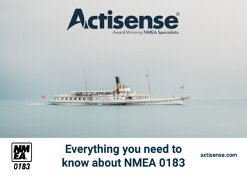
3 - Electrical SpecificationThe latest specifications for NMEA 0183 (version 2 and onwards) should, as a minimum, meet the requirements of the computer standard “RS422” (Standard EIA-422-A).They use 5 / 0 volt signalling, which is low voltage and easy to interface to computer equipment.However, voltage levels present on an NMEA 0183 network can be much greater - up to /- 15 volts, particularly where older equipment is used, as the original version 1specification used /- 12-15 volt signalling. Thus, all NMEA 0183 inputs conforming to v2.0 and higher should be capable of receiving /- 15 volt differential signals withoutsuffering damage.The NMEA 0183 specification also requires that all receiving equipment must be opto-isolated; this opto-isolation requirement reduces the chances of interference and removes the problem of ground loop effects.All connections should be made using twisted pair cabling, with a shield. To prevent ground loops, the shield should only be connected at one end - NMEA specifies that theshield should be connected to the Talker chassis.NMEA 0183 v2.x TalkersAs specified in RS422, version 2 and newer NMEA connections are labelled “A”, “B” and Shield. Sometimes the signals arelabel Data and Data -, these relate to NMEA A and NMEA B respectively.The signal states provided by the Talker are those specified in EIA-422-A. This states that the logical “1” or STOP bit stateis defined by a negative voltage on line “A” with respect to line “B”. A logical “0” or START bit is defined by a positive voltageon line “A” with respect to line “B”.A pictorial representation of an RS422 type talker can be seen in the diagram:The A is the regular output from the amplifier, and the B is the “inverted” output. The shields of all LISTENER cables shall beconnected to the TALKER chassis only and shall not be connected at each LISTENER.In practice, this means line A is zero volts and line B is at 5 volts on an NMEA output when a logical “1” is present,. For alogical “0” line A is at 5 volts and line B is at 0 volts. These voltages would be present only when no load is attached. 2021 Active Research Limited. All rights reserved.3
3 - Electrical Specification (Continued.)NMEA 0183 v1.x TalkerNMEA 0183 version 1 talkers used slightly different connection methods and signal levels. Devices had just one “NMEA”data line (‘Tx’ ‘Data’ or ‘Out’), and used the ground as the other line - similar to a computer serial port. This connectionmethod is referred to as “single ended” instead of the “differential” method used by NMEA 0183 v2.0 devices.Version 1 talkers also had signal levels similar to that used in the computer ‘RS232’ standard. Here, the data signallingvoltage was up to /- 15v, and the logical “1” or STOP bit state is defined to be within the range -15 to 0.5v. The logical“0” or START bit was defined to be within the range 4.0v to 15.0v.Other TalkersMany devices are produced that are fully compliant with the NMEA 0183 standard. Most simply label the outputs as “DATA” or “TX”, and use the system ground line as the “B”line, as per the version 1 standard, but often the drive voltage is 5 volts, as used in version 2 .Many of these talkers are labelled as version 2, but in this case they are referring to the contents of the data format, not the talker. Another limitation of these circuits is that theyoften use low power driver chips, and thus can often only talk to one listener instead of many. This means that an “NMEA Buffer” such as the Actisense NBF-3 must be used todrive multiple listeners.NMEA Talker LimitationsNMEA Talker outputs cannot be turned off, or switched into a receive mode, which means that the outputs are continuously driven.This is why only one talker can be present on a single NMEA 0183 network at any one time. To combine data from multiple talkers, you must use a multiplexer, such as theActisense NDC-5. This safely receives the data from multiple talkers, and combines it together into a single stream.Two or more Talkers are simply not possible on the same data line as they are not synchronised to each other, and will attempt to ‘talk’ at the same time (over each other).It is also likely that one Talker will have a stronger drive circuit, and the other talker will not even get to send anything.This will result in corruption or total loss of the NMEA data, and potentially in disaster if valuable data such as navigation information is lost or corrupted.Connecting two talkers together can even lead to one or both of the Talkers becoming damaged. A Talker can be connected to multiple Listeners, but often many talkers usedin electronic devices on the market do not provide enough driver current to talk to more than one or two listeners at one time, thus special NMEA amplifiers or “buffers” need tobe utilised. 2021 Active Research Limited. All rights reserved.4
4 - NMEA Listener SpecificationA listener must operate with a minimum differential input voltage of 2.0 Volts, and not take more than 2.0mA from the line at that voltage. The NMEA standard documentshows a circuit that will meet this requirement. Actisense has designed it’s own OPTO input circuit which exceeds this requirement, extending the range that valid data can besuccessfully received.A Listener must also be OPTO isolated to prevent ground loop problems. Again, many manufacturers have not implemented this and this has caused more problems ininstallations, as connecting two grounds of two systems can be a major source of faults on installations.It also causes major issues when connecting a version 2.0 Talker to a version 1.x listener, as connecting the “B” line to the ground causes current to flow every time the “B” linetries to go to 5 volts. Listeners must also be tolerant of the higher voltages used in NMEA version 1 signalling.See the ‘ISO-Drive’ section on page 10 for a solution to this problem.Communication SpecificationThe data communication specification for NMEA version 1, 2 and 3 is essentially the same as RS232 with the settings: 4800 baud, 1 start bit, 1 stop bit and “No Parity”.In addition, NMEA 0183 version 3.0 added a new baud rate of 38400 baud. This is known as “NMEA 0183-HS” This was to allow for the latest ARPA and AIS equipment whichrequire a higher baud rate link to send the larger quantity of information they produce in a timely manner.The data sent is all in printable ASCII form (data bit 7 is always zero in NMEA 0183 data transmissions, and all characters should be between ASCII HEX 20 and HEX 7E), somay be viewed directly on a PC “terminal” type program (like ‘HyperTerminal’) - even though what is seen may not make much sense.Note:NMEA 0183-HS or NMEA 0183 v3 is in no way related to the new NMEA 2000 standard (as is incorrectly suggested by some manufacturers), which uses a totally differentelectrical connection standard that is not compatible with NMEA 0183 in any way.If you require the ability to convert between NMEA 0183 and the new NMEA 2000 network, the Actisense NGW-1 Gateway will allow full bidirectional conversion between thesetwo very different standards. Please visit the Actisense website for full details. 2021 Active Research Limited. All rights reserved.5
5 - NMEA 0183 StandardThe Differing Versions of The 0183 StandardAs the NMEA 0183 specification has slowly evolved over the years, connecting one device to another is not always a simple matter.The situation is further complicated, as many manufacturers still use the old (“single ended”) method of connection because it is cheaper to implement.So how can an older type NMEA device be connected to a newer type device?Care is needed – it is possible to damage or overload the output of a newer differential device if it is incorrectly connected to an older device. This is because the older devicesused ground as the return, whereas the newer devices actually drive the NMEA “-/B” line between 5v and 0v. Thus, connecting this output to ground will result in high currentsbeing drawn by the driver instrument, resulting in potential overheating and damage to the driver circuits.Format ChangesThe data format is largely the same between versions of NMEA, with v2.0 adding some extra sentence strings, and removing older (redundant) sentence strings from thespecification.There are however problems when interfacing between version 1 and 2 NMEA 0183 where some sentence formatters were changed between the two standards. This meansthat some older equipment will not work properly when receiving data from equipment sending version 2.0 data. These changes are too fundamental and detailed to go intoin this document.Introducing Actisense ISO-Drive To solve all the above fundamental interfacing problems, Actisense implements ISO-Drive outputs on all new products. These outputs provide the essential isolation that willkeep a system safe when mixing products from different manufacturers on a complex marine bus. If the ISO-Drive “B” line is connected to ground, no current will flow and thesystem is safe.See page 10 for more information on ISO-Drive. 2021 Active Research Limited. All rights reserved.6
6 - Actisense NMEA 0183 Product RangeView the full NMEA 0183Product RangeActisense produces a full range of products to solve all NMEA interfacing and interconnection requirements, including:Multiplexers - NDC-4, NDC-5, PRO-MUX-1The Actisense mutliplexer product range can allow multiple “Talkers” to easily share their data with other NMEA 0183 “Listener”devices.All of our current multiplexer models allow for filtering of the NMEA 0183 data to remove any unwanted sentences. A wide range of input/ output Baud rates can be set to match any NMEA device. Computer users with a USB port are catered for with the later variants inthe range, either being supplied with a USB cable or having upgrade capability. Autoswitching functionality is also implemented on ourcurrent range. The latest products (NDC-5 and PRO Range) can be accessed via an Ethernet connection.Buffers - NBF-3, PRO-BUF-1The Actisense NBF-3 provides one OPTO-isolated input and six ISO-Drive outputs to allow several NMEA 0183 devices on separatesystems to safely receive the data from one source. The signal is buffered, amplified and isolated to meet the needs of any NMEA 0183network.With two NMEA 0183 inputs, twelve NMEA 0183 outputs, a bi-directional serial port and an Ethernet port, the PRO-BUF also has somefeatures seen in our multiplexers, such as Autoswitching and baud rate adjustments. The perfect solution for larger leisure vessels andcommercial shipping.Digital Transducer - DST-2The DST-2 digitises depth, speed and temperature transducer signals into NMEA 0183 data to deliver best-in-class seabed tracking.It works with NMEA 0183 compatible devices, such as chart plotters, radars or an on-board PC. In addition, it can be calibrated via a PCto match various sensors and installations.The DST-2 can be used with new or existing transducer installations. When used with an existing transducer the DST-2 can provide asecondary depth sounder as a back up to a new sonar system. 2021 Active Research Limited. All rights reserved.7
6 - Actisense NMEA 0183Product Range (Continued.)View the full NMEA 0183Product RangeGateways & PC Connectivity - USG-2, NGW-1, OPTO-4, USB-KITThe Actisense OPTO-4 allows a PC to safely receive data from an NMEA 0183 network, protecting against high voltage spikes and preventingdangerous ground loops. The cable converts between the ‘differential’ system used in the 0183 network, and the ‘single ended’ RS232 to provide thebest quality of data for the PC Port.The USG-2 is the USB to Serial (NMEA 0183) gateway. This provides a totally isolated input and output to connect a PC standard USB port to anNMEA 0183 network. With bi-directional isolation the USG-2 is even more robust than the OPTO-4.The NGW-1 converts NMEA 0183 sentences into NMEA 2000 messages and vice-versa. The NMEA 0183 end comes in standard NMEA 0183 barewire connections (ISO) or with a USB plug to connect directly to a PC running NMEA 0183 software.Watch our 20 minute webinar drawing on the benefits and pitfalls of creating a hybrid NMEA network and how to solve a number of common challengesalong the way.Demystifying NMEA DataConversions WebinarThe USB-KIT is a serial to USB cable, suitable for Actisense Devices. To safely transfer data to a PC from another manufacturers device, the USG-2is recommended for full isolation.USBKIT-PRO 2021 Active Research Limited. All rights reserved.USBKIT-REG8
7 - Connecting Talkers to ListenersConnecting NMEA talkers to NMEA ListenersCare needs to be taken when connecting different types of NMEA talkers and listeners together, particularly where a mixture of NMEA versions is encountered. Thesepages show common connections for each type of talker and listener, and how to connect between new type differential devices and old type single-ended devices.Differential NMEA TalkersCase (1): Standard differential NMEA 0183 v2.0 ListenerThis device is a differential device conforming in full to the NMEA 0183 v2.0 (or higher) standard, and connects directly to thepins on the differential device.Case (2): Single-ended NMEA ListenerTo connect the device to the differential output, connect ‘NMEA /A’ to the device’s ‘NMEA’ input and ‘Ground’ to the ‘Ground’ onthe single ended device. It should be able to receive the NMEA data correctly.Never connect the ‘NMEA -/B’ to the ground of a single ended receiving instrument. The resulting extra load will at best increasethe current consumption of the driver, at worst it could cause serious damage to it. With our products however, the Actisense ISODrive technology keeps your devices safe using this method. See next page. 2021 Active Research Limited. All rights reserved.9
8 - ISO-Drive TechnologyISO-Drive TechnologyProudly engineered by Actisense and released in 2007, ISO-DriveTM technology is unique to our products and ensures each ‘Talker’ output is protected. ISO-DriveTMprovides an isolated output, making installation simple and free from ground loops. This substantially reduces the risk of damage and hazards in connected equipment.Solves all the fundamental NMEA 0183 interfacing problems by providing the essential isolation on the Talker output to keep a system safe when mixing products from different manufacturers on a complex installation.If the ISO-Drive ‘B’ is connected to ground, no current will flow and the system remains safe.A few key points about Actisense ISO-Drive are: The ISO-DriveTM output is compatible with all connection types (RS422, RS485 & RS232), making for easy installation of an NMEA 0183 data bus system. Outputs are separately isolated from each other and the input (Listener) circuit and can ‘float’ safely up to 1500 volts D.C from system ground. ISO-Drive solves all the fundamental NMEA 0183 interfacing problems by providing the essential isolation on the Talker output to keep a system safe when mixingproducts from different manufacturers on a complex installation. Whilst we cannot get a specific number for failure rate, it far exceeds 1 : 100,000.If an Actisense product is being used that features ISO-Drive technology, then this connection is now possible and safe: 2021 Active Research Limited. All rights reserved.10
9 - Single ended TalkerSingle Ended TalkerThese are the recommended methods of connection for a single-ended, pre - NMEA version 2.0 talker.Many instruments that output version 2.0 formatted strings use a single-ended output. This is often the case with some of the hand-held GPS units such as from Garmin, as thecircuitry to produce the differential output is more complex, and requires extra connector pins.Single ended outputs are normally labelled ‘NMEA Tx’, ‘NMEA Out’ or just ‘Data’. The ground connection is used as the data signal reference.Case (1): Standard differential NMEA 0183 v2.0 Listener deviceThis device is a differential device conforming in full to the NMEA 0183 v2.0 (or higher) standard.Its “NMEA /A” input is connected to the “NMEA Tx” output of the single ended device. It’s “NMEA -/B” input is connected tothe “Ground” of the single ended device. This connection is required to provide data signal return current path for theopto-isolated NMEA listener. If the NMEA “-/B” input is left floating, then data corruption / errors may occur, or more likely, nodata will be seen.Case (2): Single ended NMEA interface devicesThis device is a single ended listener. This listener is simply connected as “NMEA Out / Data or Tx” to “(NMEA) In / Rx” and“Ground” to “Ground” of the single ended device. 2021 Active Research Limited. All rights reserved.11
10 - Connecting a Computer toan 0183 NetworkConnecting a computer to an 0183 NetworkA very common requirement now is to connect a PC or Laptop computer to the marine data network. As the NMEA specificationbasically uses the same asynchronous Comms specification in accordance with ANSI standard as used on a standard PCserial port, most PC’s can read NMEA directly through their Comms port.Many installations have been performed where the NMEA 0183 data signal of a talker is connected to the computer RS232“Rx” line, and the ground of the talker to the Computer “Ground “ connection. Do not connect the NMEA Talker “B” line to thePC ground. In our experience, almost 100% of PC’s will show the data of the NMEA link with this simple connection.These are dangerous and most definitely not recommended, as high voltage spikes can be present on the signal cable, byinduction from motors, alternators, radar pulses, high power radios etc. and will damage the Comms port on a laptop or PCthat has only been designed for domestic use.Particularly large voltage spikes can occur when engines switch on and off - outboard motors are often very hazardous to thequality of electrical signals on board a boat.Often, this connection will function for months with no problem, then fail at the worst possible time.This opto-isolation requirement was created to prevent ground loops within an NMEA 0183 network - this can be a biggerproblem than the high voltage spikes, as ground currents can destroy a PC by allowing amps of current to flow through thedelicate printed circuit boards within.It is also often the case that the PC is powered by an on board mains supply, derived from an inverter. Connecting an NMEA0183 data signal to a PC serial port directly may connect the ground of the inverter to the ground of the ship’s battery. Thiswould cause a “ground-loop” issue.Recommended connection MethodTo safely interface a serial port from a computer to an NMEA 0183 network on a boat, it is best to obtain an opto-isolatedNMEA to RS232 adapter cable such as the Actisense Opto-4.Simply plug the device into the PC port and connect the NMEA 0183 device to the wires, as per the wiring table shown here.OPTO-4 Wire ColourRedBlackBareWhiteBlue 2021 Active Research Limited. All rights reserved.Function (connects to)OPTO-4 Listener Rx A/ (Talker Tx A/ or Data)OPTO-4 Listener Rx B/(Talker Tx B/- or Ground)ShieldOPTO-4 Talker Tx A/ (Listener Rx A/ or Data)OPTO-4 Talker Tx B/(Listener Rx B/-)12
10 - Connecting a Computer to an0183 Network (Continued.)Connect to a PC without a Serial Port (Using USB)There are two ways to do this - you can purchase a USB to serial adapter, which creates a serial connection from a USB port and connect to the PC-OPTO as above.These are usually fairly cheap and easy to get hold of, however they aren’t always guaranteed to work.We recommend using one from FTDI as we have tested their RS232 and RS422 to USB Converters and have had success with them. Please note that TTL adapter cables donot work, and they must be purely RS232/422 to USB.Better still is to use an Actisense USG-2 USB to serial Gateway. This creates a totally isolated RS422 driver and receiver ready to connect safely to any NMEA 0183 network.Testing an NMEA 0183 connection to a PC with Actisense NMEA ReaderNMEA Reader is free software for PC users to easily monitor and debug NMEA data. Capable of displaying both NMEA 0183 and NMEA 2000 data NMEA Reader can be aninvaluable tool for installing an NMEA network.Example NMEA 0183 data v1.x vs v2.x The NMEA 0183 sentences differ between V1.x and V2.x . Certain fields were added in 2.x , along with checksums at the end.NMEA 0183 Sentence Format: ,M CR LF NMEA 0183 Sentence Format: (v2.0 )APB,A,A,x.x,a,N,A,A,x.x,a,c--c,x.x,a,x.x,a,a*hh CR LF »»»» Positioning system Mode Indicator field highlighted in red:A Autonomous mode, D Differential mode,E Estimated (dead reckoning) mode,M Manual input mode,S Simulator mode, N Data not validChecksum also highlighted in red. (*hh)The first difference is the mode indicator field at the end of the example sentence, which is very important as it allows the listener to understand the quality of the information.Please note that this isn’t always applicable. The second difference is the checksum field. From version 2.0 and above, the checksum field is mandatory, but is was notmandatory in version 1.5.When you look at the two sentences, it seems like there are other differences in various fields, but these are only down to clarification on the allowed formats within these fields,and should not result in different data values being seen. 2021 Active Research Limited. All rights reserved.13
11 - Understanding NMEA 0183 SentencesUnderstanding the NMEA 0183 Sentence formatAll NMEA 0183 data is sent in the form of text sentences, each beginning with a ‘ ’ or ‘!’ symbol, and use commas to separate each part of the sentence. NMEA codes are plain‘ASCII’ text, and have the following format: yyXXX, *xx 0D 0A The sentence always starts with a ‘ ’ or ‘!’ symbol A 2-digit ‘yy’ code follows, giving the instrument type (e.g. for a GPS device this should be ‘GP’, and for a depth sounder this should be ‘SD’) A 3-digit ‘XXX’ code follows, giving the sentence data type (e.g. ‘GGA’ is a ‘Global Positioning System Fix Data’ sentence, and ‘DBT’ is a ‘Depth Below Transducer’ sentence) A comma follows, then the contents of the sentence data, which changes depending on the data type and the current values of what is being monitored. The final part is a two-character checksum. All equipment which utilises NMEA 0183 v2.0 will include this to help safe-guard the data in the sentence. The checksum ispreceded by the ‘*’ character and is calculated by taking the 8-bit exclusive-OR of all characters in the sentence, including ‘,’ delimiters, between but not including the ‘ ’ /’!’ and ‘*’ delimiters. The string always ends with a carriage return and line-feed combination (Hex 0D 0A, ASCII ‘\r\n’)Here is an Example sentence which better explains the NMEA 0183 Sentence format: SDDBT, Water Depth, feet, Water depth, Meters, Water Depth, Fathoms*Checksum SDDBT,556.3,f,169.6,M,92.7,F*37This is Broken down into the following fields: SD Depth SounderDBT, Depth Below Transducer556.3,f, Measurement in ft169.6,M, Measurement in Meters92.7,F Measurement in Fathoms. 2021 Active Research Limited. All rights reserved.14
12 - Useful NMEA ResourcesNeed further support with your NMEA 0183 Network? Here is a directory of useful contacts:National Marine Electronics AssociationEmail: info@nmea.orgTel: 410-975-9425Website: www.nmea.orgActisense (Active Research Ltd)Technical Support: support@actisense.comStock availability & distributor enquries: sales@actisense.comTel: 44 (0) 1202 746682Website: www.actisense.comVisit our extensive Knowledge Base for frequently asked question - www.actisense.com/knowledge-baseView the full Actisense NMEA 0183 product range: 2021 Active Research Limited. All rights reserved.NMEA 0183Product Range15
As specified in RS422, version 2 and newer NMEA connections are labelled "A", "B" and Shield. Sometimes the signals are label Data and Data -, these relate to NMEA A and NMEA B respectively. The signal states provided by the Talker are those specified in EIA-422-A. This states that the logical "1" or STOP bit state