Transcription
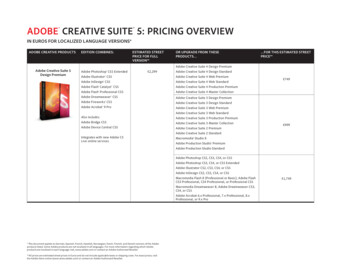
R333 Bayview AvenueAmityville, New York 11701For Sales and Repairs, (800) 645-9445For Technical Service, (800) 645-9440 or visit us athttp://tech.napcosecurity.com/(Note: Technical Service is for security professionals only)Publicly traded on NASDAQSymbol: NSSC NAPCO 2013iBridge Suite Quick StartInstalling the IBR-ZREMOTE Z-Wave Controller,ISEE-WAP Wireless Access Point and theIBR-ITAB Wireless Touchscreen TabletWI1980B draft .09 05/13 CONTROLPANELHome ControlNetworkIBR-ITABiBridge Touch Screen Tablet KeypadInternetVisit us at http://www.napcosecurity.com/1
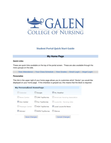
Overview of the NAPCO iBridge IBR-ZREMOTE Z-Wave ControllerGeneral OverviewThe iBridge IBR-ZREMOTE is a Local and Remote Control Module and ZWave Controller that allows control of security, video, locking, lighting andclimate control from inside or outside your home. Z-Wave devices may beenrolled, removed and formed into a Z-Wave wireless home controlnetwork, and also integrated with Napco's iBridge suite of services thatincludes access to the iSee Video remote video Internet monitoringsystem.Compatibility with the iSee Video VideoAlert system allows an email or textmessage to be sent when a selected control panel event occurs. Inaddition, acting as a wireless Z-Wave controller, the IBR-ZREMOTE cantrigger Z-Wave network devices upon control panel events. For example,upon system arming the IBR-ZREMOTE can turn lights on or off, adjustthermostats, email video clips, etc.The IBR-ZREMOTE is wired to the control panel keypad bus, andcontinually monitors all changes to the status of the system and triggersactions based on user or dealer entered programming.Note: Z-Wave enabled devices displaying the Z-Wave logo can usually beused with the IBR-ZREMOTE module regardless of manufacturer, and theIBR-ZREMOTE module can also be used in other manufacturer's Z-Waveenabled networks. For an iBridge Z-Wave Evaluated Device List, seeour website at www.napcosecurity.com/ibridge.html.KEYPAD BUSKEYPADCONTROLPANELTO PANEL SERIAL PORT(only needed for NL-MODCS communication)IBR-ZREMOTEiBridge OnlineTo access the IBR-ZREMOTE remotely via PC, tablet or smart phone, orto provide remote services for a customer, the dealer must have an iBridgeonline account. Go to www.ibridgeonline.com/ibridge to access yourexisting account or register for a new account. Device apps are availablefor iPhones, iPads and Android devices from their respective appsmarkets.NETWORKNETWORKWith the IBR-ZREMOTE, actions performed at the keypad can beperformed remotely. Add the IBR-ZREMOTE to a Napco control panel bysimply programming an additional keypad address into the control panel,set the IBR-ZREMOTE to this new keypad address and enroll the IBRZREMOTE into your subscribers account.Alarm Reporting((((((Remote ControlBROADBANDMODEMThe IBR-ZREMOTE is also an Internet reporting module, capable ofreporting alarms and events to any central station equipped with theROUTERISEE-WAPNapco NetLink NL-RCV-RMPCUL central station receiver or NetLink NLCSRCV central station software application. The IBR-ZREMOTE also permits high speed upload/download of thecontrol panel through the Internet. Refer to manuals WI1491 (NL-RCV-RMPCUL) and OI294 (NL-CSRCV) for details.Overview: Home Control NetworkA home control network is a system used for controlling lights, appliances, air conditioning, heating, burglary alarmsystems and other devices within a home or office. Z-Wave is a reliable and robust wireless home control networkstandard created by Zensys, Inc. (www.zen-sys.com), operating within an interconnected "mesh" network where at leasttwo pathways exist for each device (thus if one pathway fails, another is still available). In addition, Z-Wave devicesoperate within the 902-928 MHz band, and therefore will not interfere with Wi-Fi and other devices using the 2.4 GHzband.The simplest Z-Wave network consists of a primary "controller" and single controllable device or "node" such as a lightswitch, thermostat, etc. Additional controllers and devices can be "included" into (or "excluded" from) the network at anytime, usually by means of button presses on both the controller and the device. The IBR-ZREMOTE module can act asa "primary" controller to setup and maintain the network, or can act as a "secondary" controller within an existing Z2
Wave network previously started by a "primary" controller (from any manufacturer).Note: As the signal strength between the IBR-ZREMOTE controller and its devices is crucial, we recommend all devicesbe mounted in their final installed locations before they are included into the network.Ordering Information IBR-ZREMOTE: Bus-Mount Module for remote control, up/download of security system, plus control of Z-Wavedevices, lights, locks, thermostats, etc. IBR-ITAB: iBridge Wireless Touchscreen Tablet with mounting frame and charging station. IBR-ITABKIT Kit: iBridge Wireless Touchscreen Tablet with mounting frame/charging station plus Wireless AccessPoint (ISEE-WAP). IBR-ITAB-HW: Hardwired iBridge Touchscreen Tablet version for permanent mounting and for a more conventionalhardwire installation. ISEE-WAP: Wireless Access Point for wireless communication between IBR-ITAB and wireless cameras. IBR-ITABSTAND: Angled tabletop stand/docking station for use with IBR-ITAB Touchscreen (not included). Décorneutral and ideal for bedrooms, kitchens, desks, etc. IBR-WIFI-MOD: Wireless Panel Interface, communicates between Internet, Gemini Control Panel and IBR-ITABTouchscreen Tablet, when NO remote services or Z-Wave are required (Note: For remote services and Z-Wave, usethe IBR-ZREMOTE).For an iBridge Z-Wave Evaluated Device List, see our website at www.napcosecurity.com/ibridge.html. Although all ZWave appliances should comply with the Z-Wave standard, we recommend that you install only Napco evaluated devices,especially the more complex devices such as thermostats and door locks.SpecificationsDimensions: 1½" x 7" x 4¾" (HxWxD)Input Voltage: 13.0-10.0VDC.Input Current: Maximum current (@ 8VDC) 185mANominal current: @ 12VDC 185mA (supplied by control panel connections).Available panel combined auxiliary current is reduced by 185mA.Outputs: PGM-style open collector (negative trigger) with a maximum sink current of 50mA.Factory Default Settings The IBR-ZREMOTE factory default settings for the NL-MOD and NL-RCM modules are:Account ID FFFFFFDealer ID NAP0000Keypad Address 1Keypad Type RP1CAe2PC Preset / DNS IP Address 72.3.180.2PC Preset / DNS Port 5002PC Preset / DNS Check-In Time 1iBridge Server IP Address 208.109.208.163iBridge Server Port 50113
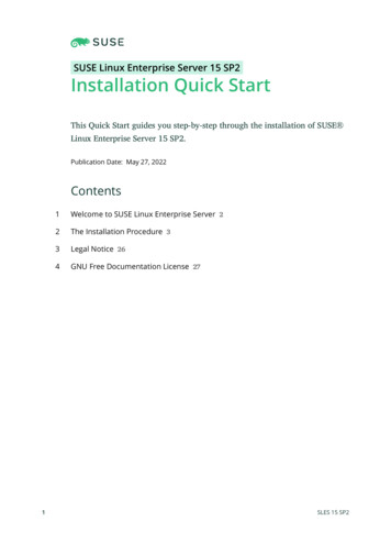
Installing the IBR-ZREMOTE Z-Wave Controller, ISEE-WAP WirelessAccess Point and the IBR-ITAB Wireless Touchscreen TabletThe iBridge Suite allows consumers to control their alarm system, Z-Wave devices and video cameras from wirelessand wired Touch Screens, Android and Apple devices and from a PC web browser independently or all at the same timefrom inside the premises or out.This guide will walk you through the steps required to set up a typical system. The key components are: IBR-ZREMOTE: This the "hub" of the system. It links the Napco alarm control panel keypad bus, a Wi-Fi accesspoint, and an internal Z-Wave controller allowing commands to flow from one system to another via aninterconnected TCP/IP network within the premises or over the Internet. The IBR-ZREMOTE also has an integral NLMOD to allow the reporting of alarms to a Napco NetLink Receiver and to remotely configure the alarm control panelover the Internet. Because the IBR-ZREMOTE is connected to the Napco keypad bus, it must be programmed with aunique keypad address number. It is shipped defaulted as KEYPAD ADDRESS number 1, but is easy to change. ISEE-WAP: This is the Wi-Fi access point that allows wireless devices (cameras, Touch Screens, etc.) to gainaccess to the IBR-ZREMOTE and the TCP/IP network. (Not required if not using cameras or IBR-ITAB wirelessTouch Screen). IBR-ITAB: This is a completely wireless Touch Screen that connects to the ISEE-WAP using built in Wi-Fi for controlof Security, Z-Wave and Video. The IBR-ITAB-HW is a slight variation of the IBR-ITAB and differs in themanagement of the security connection. In this case the IBR-ITAB-HW is wired directly to the Napco control panelkeypad bus to control security and the integral Wi-Fi is used only for Video and Z-Wave control.The overall system layout is shown below:WIRING OVERVIEW with IBR-ZREMOTE and PADRemote ServicesNETWORKGREENREDYELLOWKEYPAD BUSBLACKREDBLACKGREENYELLOWNETWORKTO PANEL SERIAL PORT (onlyneeded for IBR-ZREMOTE CScommunication or ((IBR-ITAB-HW4Z-WAVE DEVICESCAMERASIBR-ITABCUSTOMER ROUTER(Wireless or Wired-only)ISEE-WAP
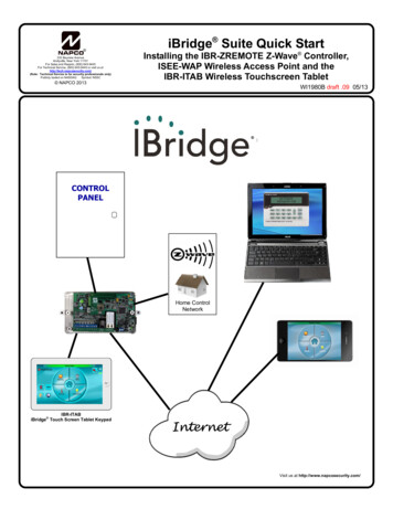
CLOSE-UP VIEWCUSTOMER'SBROADBANDCONNECTION(MODEM ORNETWORK)WAN(INTERNET)(CUSTOMER'SPC AND AL ROUTER REAR PORTARRANGEMENT12V/1AWAN4321ISEE-WAPISEE-WAP REAR PORTS (DO NOT USE WAN PORT)The system can be installed out of the box without any configuration changes. First ensure the alarm control panel is wiredand working with a standard wired keypad as KP ADDR #1 before you continue. Be sure to use the same "type" of keypad(either "Classic" or "K Series" Stay/Away) that you plan to configure the system to use. Do not wire the IBR-ZREMOTE yet.STEP 1: PREPARE THE IBR-ITABThe IBR-ITAB has an internal battery that may need recharging. Press and hold the "Back/Power" button(shown at right) until the display starts to turn on (then release the button). After the IBR-ITAB tablet starts,observe the battery indicator icon (upper right); if green or yellow, the battery has enough charge to completethe installation. Press and hold the "Back/Power" button again until the power off message appears andturn off the tablet. If the battery indicator icon is red, you can install and mount the charging plate asdescribed in WI1944 or just connect the power adapter to the charger plate (observing polarity) and powerthe IBR-ITAB to continue.Back / PowerButtonSTEP 2: CONFIGURE THE CONTROL PANELThe alarm control panel must have the correct firmware version installed to utilize all features of the IBR-ZREMOTE.Required are: PCD-Windows Quickloader: V6.12 or greater (located on the enclosed IBR-ZREMOTE support CD) Control panels GEM-X255, GEM-P9600 and GEM-P3200: Firmware version 60A22-4 or greater (included inIBR-ZREMOTE box) Control panels GEM-1664, GEM-P1632 and GEM-P816: Firmware version 30R-9 or greater (included in IBRZREMOTE box)Note: The following version control panels may be upgraded for iBridge compatibility: GEM-P3200 and P9600 controls running firmware version 20 or greater, released in May of 1999. GEM-P816, P1632 and P1664 controls running firmware version 30 or greater, released in August of 1999 (V10can be used if a 32 pin socket is available on the control panel motherboard).Perform the following:2A. If installing the IBR-ZREMOTE on a previously programmed control panel, launch Quickloader 6.12 and upload thecontrol panel program configuration to an account on your PC. In all cases ensure a conventional keypad isconnected at keypad address 1 for steps that follow.5
2B. Remove power from the control panel, disconnect the battery wires and replacethe EPROM with the new version.2C. Power up the control panel and reconnect the battery wires. Enter Direct AddressProgram Mode and Cold Start the control panel (refer to the enclosedprogramming instructions WI2052 for the procedure).2D. Download the saved control panel program configuration back into the controlpanel or create and download new control panel programming.2E. In PCD-Windows Quickloader, select the keypad address to be used for the IBRChange keypad Type to "RCM"ZREMOTE; change the keypad Type for that keypad address to "RCM" (as shownin the image at right), select EZ Arm (6 columns to the right on the same screen). In the Keypad Features tab,check "Disable Code-Required-for-FM-Level 1". Download to the control panel (all IBR-ZREMOTE modules arefactory defaulted as keypad #1). Change the conventional wired burglary keypad that was keypad #1 to keypad #2.Note: If this is your first installation, we suggest you leave the IBR-ZREMOTE at KP ADDR #1 and change theconventional wired keypad to ADDR #2 as described in these instructions.STEP 3: INSTALL AND WIRE THE IBR-ZREMOTEThe IBR-ZREMOTE requires a unique keypad address on the NAPCO keypad bus. The IBR-ZREMOTE is factoryconfigured as control panel keypad address #1 and as a Napco "Classic" keypad. Place the panel configuration jumperinto CONFIG mode and leave this jumper there for now. The keypads will be configured in step 5.Disconnect power from the control panel (AC and battery) and connect the keypad bus wires as shown below to the 12V, GND, GRN and YEL terminals.CONTROLPANELTO PANEL SERIAL PORT (only neededfor NL-MOD CS RJ45CABLE4 WIRERJ12CABLE3 WIRE10R.B.9SUPV.8IN37IN26IN15IN04BELL3DATA2GND 12V1HEADERSOCKETMAC Address(Example:00-20-4A-8081-8B)BLKREDJ3GRN YELSTEP 4: WIRE THE NETWORK CONNECTIONUse standard CAT5 network cables as follows: Plug one end of a CAT5 cable into an open LAN socket on thecustomer's existing router and the other end into an open LAN socket of the ISEE-WAP. Plug one end of a secondCAT5 cable into another open LAN socket on the ISEE-WAP, and the other end into the IBR-ZREMOTE receptaclelabeled "ETHERNET". Then plug one end of a third CAT5 cable into another open LAN socket on the ISEE-WAP, andthe other end into the other IBR-ZREMOTE receptacle located on the right side of the IBR-ZREMOTE. Refer to thediagram on page 4 if needed. Note: Customer's router must support DHCP.Reconnect the battery connection and power the control panel. Wait two (2) minutes for all devices to fully power andcomplete their network connections. Remember, the panel configuration jumper is set to CONFIG mode, so thekeypads will power up and display "OUT OF SYSTEM".STEP 5: CONFIGURE THE IBR-ZREMOTE AND KEYPAD ADDRESSES5A. If the IBR-ZREMOTE is to be keypad address #1 and set as a Napco "Classic" keypad, then set the keypadaddress in the conventional wired keypad to keypad address #2 as you normally would using KeypadConfiguration Mode (press 11123 FUNCTION). If you have more than one conventional wired keypad, verifyeach address is unique. If not changing the IBR-ZREMOTE, then move the panel CONFIG jumper back toNORM and go to step 7. If the IBR-ZREMOTE is changing, then the basic procedure is to enter KeypadConfiguration Mode and set the KP ADDR and Keypad Type to the desired values.6
5B. The IBR-ZREMOTE keypad address and Keypad Type can be configured in one of three ways: Use an IBR-ITAB Use an app on your iPhone, iPad or Android device Use a Napco GEM-RP1CAe2 or GEM-K1 keypad with a special programming cableUSING THE IBR-ITABIf step 4 was completed properly, the IBR-ZREMOTE and ISEE-WAP should have obtained IPaddresses and be ready for use. Power up an IBR-ITAB and it will connect to the ISEE-WAP andIBR-ZREMOTE automatically (this process may take several minutes the first time it is performed).The top status bar will display "Not Ready To Arm" when it is ready for the next step.First set the keypad skin for the IBR-ITAB. On the IBR-ITAB, press and hold the button with theSystem Settings "gear" icon on the lower left corner of the display for 4 seconds. Tap the empty Back / PowerButtonfield and in the keyboard type the administrator password "admin"; tap Done and then tap OK.Tap Yes to the "Making System Changes " popup, then tap Security. Tap the first menu entry Keypad Skin,then tap either Classic or K Series Stay/Away. Press the Back/Power button twice to return to the keypaddisplay. Next, set the keypad type in the IBR-ZREMOTE.Tap Security Other Options Keypad Mode. The keypad will display "01 Out of System". Tap 1 1 1 2 3FUNCTION to enter Dealer Mode. Tap FUNCTION or MENU repeatedly until the configuration keypad displays"Keypad Address". Enter the correct address and tap ON/OFF or ENTER to set. Tap FUNCTION or MENUrepeatedly until the configuration keypad displays "KEYPAD TYPE RP1CAE2" (tap INTERIOR / STAY orNEXT to toggle between the keypad model names. Note: If using a physical K Series ("Stay/Away") keypadconnected with a wire harness, press and hold STAY until it beeps to toggle between the keypad modelnames). When selected, tap ON/OFF or ENTER to set, then tap RESET to exit.Return the CONFIG jumper on the control panel back to NORM ("System Ready" should appear on the keypadif all zones are closed).USING AN APPIf you have already loaded the iBridge App on your device, then connect to the ISEE-WAP Wi-Fi access point"IBRIDGE" using the WEP key 1234567890. Repeat the same steps in the section "USING THE IBR-ITAB"above. If for any reason you cannot connect with the IBR-ITAB or the phone app, then the "USING ACONFIGURATION KEYPAD" procedure (below) can be used.Apps can be obtained from Google Play or the Apple Store.USING A CONFIGURATION KEYPADA GEM-RP1CAe2 or GEM-K1 keypad (henceforth called a "configurationkeypad") can be plugged into the IBR-ZREMOTE "Header Socket" receptacle(marked "J3" on the PC board; see the image at right). When connected, the IBRZREMOTE can be configured exactly the same way as a physical Gemini keypad.Connect one end of the provided RCM-PROGCABLE keypad bus cable to theGemini keypad, then connect the other end to the IBR-ZREMOTE circuit boardreceptacle marked "J3" (keying tab faces away from unit).J4J3Configuration ProcedureUse the "configuration keypad" to program the IBR-ZREMOTE KP ADDR andKeypad Model as follows:a. Ensure both jumpers marked J2 and J3 located on the lower PC board(next to the blue bus connector) are set closer to the "4-WIRE" printing onthe PC board (this is the default shipping configuration).RCM-PROGCABLE plugs into the"Header Socket" (J3)Jumper J4 also shown.b. Remove jumper J4 on the Z-Wave PC board (located on the top PC board in the IBR-ZREMOTEhousing, next to silver battery).c. Connect one end of the special keypad bus cable (RCM-PROGCABLE) to the back of the configurationkeypad and connect the other end to the IBR-ZREMOTE "Header Socket" receptacle (marked "J3" on thePC board). The control panel CONFIG jumper should still be set to CONFIG from step 4. When theconfiguration keypad powers up, its display will read "XX OUT OF SYSTEM". IMPORTANT: After thedisplay reads "XX OUT OF SYSTEM", you MUST stop and wait the IBR-ZREMOTE components to resetand prepare for communication; only after the display changes to "XX OUT OF SYSTEM RCMMODULE" may you proceed with the next step (the words "RCM-MODULE" must be in the display text).7
Repeat the same steps in the section "USING THE IBR-ITAB" above. When finished, disconnect the cableand be sure to reinstall jumper J4.At this point you should have a functioning system and be able to arm and disarm the panel using the IBR-ITAB. Thenext step is to integrate video cameras (if applicable).STEP 6: ENROLL VIDEO CAMERAS (Optional)If you already have iSeeVideo cameras installed, then jump to the next paragraph "Discovering Cameras" below.Installing CamerasMount and wire cameras in accordance with the work instructions included with the camera. Make note of the MACaddress of each installed camera. Once the cameras are installed (wired or wireless), power them and wait at leasttwo (2) minutes for the cameras to acquire IP addresses and stabilize.Discovering CamerasOn the IBR-ITAB Touchscreen, tap the VIDEO "pie shape", then tap the magnifying glass that appears on the nextscreen to discover the newly installed cameras (or the existing iSeeVideo cameras installed previously). It may benecessary to re-run this discovery process more than once if all cameras are not found.STEP 7: ACTIVATE AN IBR-ZREMOTE ACCOUNT FOR "REMOTE SERVICES"Once the IBR-ZREMOTE has been completely wired to the control panel, configured and powered up, a consumeriBridge subscriber account is ready to be created for remote services (remote access through the web andsmartphones), if desired. These activation steps include adding Subscribers, cameras and an IBR-ZREMOTE to acustomer account.NEW ACTIVATION7A. To create your new iBridge subscriber accounts, simply type thefollowing Internet address into your Web browser:www.ibridgeonline.com/ibridge.and the following web page appears: If you are not yet registered as a Dealer, simply click Register a Dealer to submit a registration request (you mustbe a registered dealer to create subscriber accounts) If you already have a Dealer account, type your UserName and Password and click Submit and the Welcome screen appears7B. In the Welcome screen, click User Management ManageSubscribers. The Subscribers Listing page appears.Click Add New Subscriber. In the Subscriber Registrationform, type the subscriber's name, address, telephone numberand other information in the appropriate fields as shown in theimage at right. When finished, click Create.Note: After clicking Create, scroll below the Subscriber Information to find the subscriber automatically added as a new"Master" End User (the person having administrative privileges,i.e. the ability to program Advanced Settings and add new EndUsers to the account).8
7C. Near the bottom of the screen, click Add / Replace Newi/z Remote Device.In the popup that appears, type the uniqueMAC Address of the IBR-ZREMOTEprinted on the label on the jack markedETHERNET. Type the complete 12-digitcode (do not enter dashes).MACADDRESSKeypad SelectionClick the Keypad selection pull-downmenu to select the keypad type of the installation. Thisshould be the same keypad type installed in step 5.Note: For the -2AS, the -3DGTL and -4RF series, thecorresponding full alpha keypad will be displayed, allowing the entry of zone descriptions, if desired.Click Submit ¼ and the new IBR-ZREMOTE will beadded to the account.7D. Next, add any video cameras to the account by typing theMAC address of the cameras you wish to view remotely.This step is required even if the cameras are existingiSeeVideo cameras. Above the zRemote entry field youwill see the Add New Camera button shown at right:Simply click on Add New Camera and type the MAC address in the field provided. If you previously enrolledcameras to your Dealer account but did not assign themto a Subscriber account, then you can select "Add fromExisting Camera Device List" to find the cameras andassign them to the Subscriber.Click Submit and then add additional cameras if needed.7E. Be sure to select the services to be made available toyour customer by checking the appropriate boxes. Bychecking Video, Security and/or Z-Wave, customers cancontrol these functions via the web. Only by checkingRemote Access can your customers remotely log in andconnect using Apple and Android devices ("Remote Services").7F. Verify the user account is functioning by logging in to thefollowing Internet address using your Web browser:www.ibridgeonline.com/ibridgeEnter the customer User Name and Password created in9
step 7B above, and verify that the image shown at rightappears.Verify the system can be armed and disarmed and thatthe cameras, if installed, are visible. The consumer canchange the User Name and Password by accessing theweb account.STEP 8 – SECURING THE SYSTEMUp to this point the iBridge system auto-configured using the default Wi-Fi settings. The ISEE-WAP has two defaultSSIDs (network access point names) broadcasting to devices within signal range of the ISEE-WAP; these SSIDscan easily be seen with any iPhone or Android device. The names are PUBLIC and IBRIDGE. SSID1 is namedPUBLIC and is used by the IBR-ITABs and cameras to automatically join the network. SSID2 is named IBRIDGE,uses the WEP security protocol and a 10-digit Key of "1234567890". SSID2 can be changed to a new name and asecret Key so that only the customer has access. After this step is completed, PUBLIC can be disabled so that noone else can connect to the system. Note: This process is reversible to accommodate future changes.The following steps will ensure that the IBR-ITAB will onlywirelessly connect to the intended ISEE-WAP by adding theunique SSID name and (secret) key to the ISEE-WAP.With the Home Screen displayed, using your finger, pressand hold the System Settings "gear" icon (shown at right).Press and hold the"System Settings""gear" iconThe Please enter password popup appears (shown at right).If this popup does not appear, press the Back/Power Buttonand try again. Remember, be sure to press and hold the System Settings "gear" icon.In the Please enter password popup, tap the blank (empty)field with the flashing cursor, and the following keyboard willappear on the screen:Using the keyboard keys, tap each letter to type the word"admin" (all lowercase). When finished typing, tap the Donebutton (see image at right).10Done button
The word "admin" is now placed in the Please enter password popup, as shown:Tap OK. The following warning popup appears:Tap Yes and the following User Settings menu appears:Tap Tablet, then tap Connection. The following Connection Settings appears:Change the SSID and Key.Tap (1) Change/Create CUSTOM IBRIDGE ISEE-WAPSSID and KEY.Note: The following only needs to be performed once toconfigure or change the ISEE-WAP. If enrolling a secondIBR-ITAB, jump to the next step.An Information popup appears:11
Tap Continue. In the Preferred Network dialog that appears (shown at right), type a new SSID name, ensure thedefault security protocol is WEP, then type a new secret Key(check Show Password to view the password text as youtype). The Key MUST be one word (no spaces) 10 digits inlength using only 0-9, A, B, C, D, E or F as digits. DO NOTuse the same SSID name and secret Key as the customer'srouter. Again, do not use spaces!When finished, tap Save. This action adds this unique SSIDand this unique Key to the ISEE-WAP. A popup will displaythat reads, "Command completed successfully -- OK".Tap OK to close; wait two (2) minutes for the ISEE-WAP torestart and the IBR-ITAB to reconnect.Next, you must configure the IBR-ITAB to hereafter ONLYconnect to the ISEE-WAP with this unique SSID and thisunique Key. Proceed as follows:Choose the Tablet Connection/SSID.At the Connection Settings menu that appears (shown atright), tap (2) Tablet Connection/SSID Choice.In the following Information popup that appears, tap Continue.In the screen that appears, tap CUSTOM SETUP.Under CUSTOM SETUP you will be presented with thesame Preferred Network dialog above. The data enteredpreviously will still exist; tap Join to accept this data. Note:If enrolling a second IBR-ITAB, these fields will have to becompleted using the same data you entered previously withthe first IBR-ITAB.12
Configure the Wireless Cameras. Be sure all wirelesscameras are powered, then tap (3) Configure WirelessCamera.A confirmation popup appears; tap Yes to proceed (or tapNo to exit without saving changes).Wait while the IBR-ITAB searches for all cameras. Whenfinished searching, the IBR-ITAB lists all the discoveredcameras by IP address. Tap to select each camera one at atime and tap "Lock" to lock the camera. Exit when complete.Lock Down the ISEE-WAP.In the Connection Settings menu, tap (4) Lock DownIBRIDGE ISEE-WAP.Locking the ISEE-WAP turns off the default "PUBLIC" SSIDso no other systems can connect to your equipment. Anynew IBR-ITABs will have to use the new SSID and Key entered in the Preferred Network dialog above.In the Information popup that appears, tap Continue.Wait several seconds until the following popup appears:Tap OK to close.13
Test the keypad. To ensure the IBR-ITAB is connected withthe correct ISEE-WAP, press the Back/Power Button repeatedly until the Home Screen appears, then press the Security button. A screen with your arming choices appears:Arm the system by first pressing AWAY, then press the UserCode in the keypad that appears. Ensure the keypad text onthe IBR-ITAB matches the keypad text that appears on thestandard wired keypad.In the Home Screen, when connected, a connection strength indicator appears at the topright (1-4 bars, as shown). If you wish to verifythe connection, press this icon and text appears at the bottom of the IBR-ITAB screen Signal StrengthIndicatorconfirming the validity of the connection. Forexample, the text may read:"Connected with ssid:WAP345, Level: Excellent, IP:192.168.50.102, Port: 8003, Gateway: 192.168.50.2"At this point you have successfully installed, configured and locked down the iBridge system. Additional manuals areincluded with this system as follows:Z-WAVE PROGRAMMING AND USER GUIDE (OI378)If your customer plans to use Z-WAVE devices, then consult OI378, "Using your iBridge IBR-ITAB Series HomeAutomation System". This user guide describes how to enroll and control Z-Wave devices. As a Dealer, you havethe choice to either allow or disable access to Z-WAVE configuration menus by the end user. This setting isdiscussed in the following WI1944.CONFIGURING THE IBR-ITAB (WI1944)The IBR-ITAB Installation, Mounting and Programming instructions describes how to physically install the IBR-ITABto the wall and also describes the three (3) types of menus in the IBR-ITAB. They are:1. User Settings: User Settings are options that your customer can set to control the IBR-ITAB. Tap the SystemSettings "gear" icon once (lower left corner of the Home screen) to access this menu. Descriptions of eachfeature are described in the IBR-ITAB Security System User Guide OI372.2. Dealer Settings: Dealer Settings are options that the Dealer configures. These menus are accessed via thesame "gear" icon but by pressing and holding the "gear" icon for 3 seconds (a password is required to accessthese menus).3. Android Settings: Within Dealer Settings there is an option to access the Android menu system. The An
2 Overview of the NAPCO iBridge IBR-ZREMOTE Z-Wave Controller General Overview The iBridge IBR-ZREMOTE is a Local and Remote Control Module and Z- Wave Controller that allows control of security, video, locking, lighting and climate control from inside or outside your home. Z-Wave devices may be e