Transcription
Fatigue Analysis for Coiled TubingFACTVersion 1.xxUser ManualCourtenay House, Monument Way East, Woking, Surrey GU21 5LY, U.K.Tel: 44-1483 750600 Fax: 44-1483 762233Email: support@medcotas.comHome Page: http://www.medcotas.com
Table of ContentsOverview. 3Theoretical Background. 4Effect of Equipment Size. 4Effects of Axial Stress on Fatigue Life. 5Effects of Pressure. 7Effects of Weight. 7Other Effects. 7Material Strength . 7Welds. 7Corrosion . 7Reliability of Empirical Data. 8Using FACT . 9Job Related Data. 9Gooseneck Radius . 9Distance between Reel to Gooseneck. 9Distance of Gooseneck to Stripper . 9Bottom-hole Assembly Length. 9Coiled Tubing String/Reel. 10FACT Modes of Operation – Automatic and Manual . 10Converting to API English units. 11Creating New String. 12Entering Job Events Data . 14Reviewing String History. 16System Maintenance. 17Manipulating Coiled Tubing Strings . 18Cutting and Dispose CT . 18Spool and Cut . 18Spool to another reel. 18DataBase. 20Corrosion and Weld Factors . 20Coiled Tubing. 20Fatigue Cycles . 21Program Options . 222
OverviewFatigue Analysis for Coiled Tubing, FACT version 1.xx, is the latest of the coiled tubing fatiguemodule produced by MEDCO. This program performs fatigue analysis and tri-axial stresscomputations of coiled tubing in real time, in post-job mode, and/or using manual data entry.The fatigue analysis takes into account the geometry of the coiled tubing, material properties, and theequipment used. In addition, corrosion, stress concentrations, and statistical reliability of the empiricaldata are also considered. FACT keeps track of the coiled tubing fatigue history per job, and gives theuser the option of reviewing the fatigue history at any moment of time.In keeping an accurate account of the fatigue history, this program is a vital tool for managing thecoiled tubing strings without the risk of failure.Coiled tubing goes through several plastic deformation cycles through it's usage in and out of wells.The first deformation cycle takes place as the coiled tubing leaves the reel, where the coiled tubing isdeformed from being bent to being straight. Next are two cycles of deformation while going throughthe gooseneck, straight to bent and bent to straight. These cycles are experienced both ways, i.e. whengoing into the well and when pulling out of the well. Thus the total number of cycles of plasticdeformation will be six.During a coiled tubing job, the coiled tubing is further cycled by the operators, when performing a pulltest, for example. But some of these may work part of the coiled tubing over the gooseneck only andother parts that may have left the reel would go back on the reel but do not reach the gooseneck. Thus,to have an accurate record of the cycles, knowledge of the distance between the reel and the gooseneckis required.The above is only concerned with plastic deformation of the coiled tubing due to axial loading andunloading. The axial forces impose axial stresses that are in excess of the material minimum yieldstress. However, our concern is the total stress and not just the axial stress. Thus, internal pressure,corrosion, and stress concentration due to welds and/or presence of H2S sour gas all become pertinent.A special technique is utilized to account for each of these effects.The internal pressure will change the hoop and radial stresses and these can be simply calculated andthus the total stress computed accordingly.Corrosion and stress concentrations are more difficult to account for. Corrosion will normally reducethe wall thickness of the coiled tubing, however, we do not have an exact measure of how much wallthickness is lost and until such measures become known, we have to make some assumptions toaccount for the loss of wall thickness. Clearly, the wall loss will reduce the coiled tubing crosssectional area thus increasing the stresses due to the same load being applied. A number of corrosionfactors have been suggested and are basically representative of reduction of wall thickness, i.e. arealways less than 100% (in FACT less than 1). Similarly, stress concentration factors are assumed forwelds and H2S gas and these basically mean that the stresses are increased because even before loadinglocally concentrated stresses exist. Again, stress concentration factors are less than 100% (in FACT lessthan 1).Finally, when a corrosive fluid is pumped through the coiled tubing, the wall loss will take placethrough the entire length and not just the parts that moved out of the reel. However, FACT will onlysubject the coiled tubing to stresses if it has moved during the job. Thus to account for the wall loss dueto internal corrosion, the whole length of the coiled tubing is cycled once in and out of the well towardsthe end of the job. (When the PULL OUT button in FACT is clicked).3
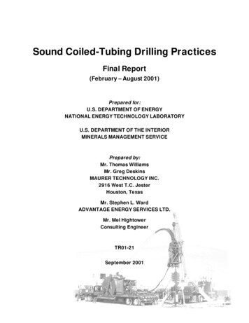
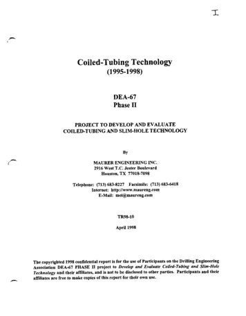
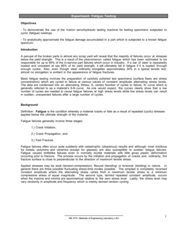
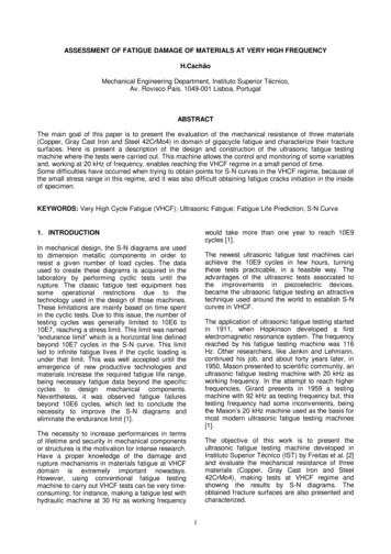
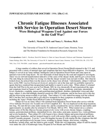
Theoretical BackgroundThe stress-strain relationship given by Hooke’s law, dictates that the coiled tubing must not exceed theminimum yield stress, σy, to remain within the elastic range of the curve. Since the slope of the curve isgiven by the Young modulus, E, the following condition for the strain, ε, must be satisfied to remainwithin the elastic range;ε σyE. 1Figure 1: Hooke’s law for the stress-strain relationshipIf we were to substitute the values of the minimum yield stress and the Young modulus of elasticity forcoiled tubing QT-700, say, then we obtain a maximum strain of 7/3x10-3 (E 30 x 106 psi, σy 70,000psi).CT outerdiameter, doRadius ofCurvature, RFigure 2: Geometry of coiled tubing when subjected to bendingEffect of Equipment SizeIn figure 2, if we assume the radius of curvature over which the coiled tubing is being bent to be R, andthe coiled tubing outer diameter to be do then the length of the non-deformed coiled tubing is given by;L 2π ( R do)2. 2While the length of the outer side of the coiled tubing is given by;L ΔL 2π ( R d o ). 34
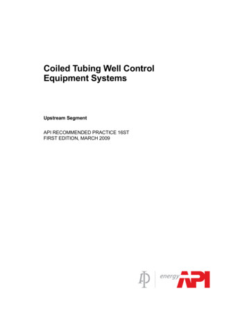
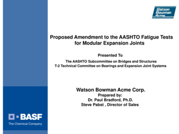
Therefore, the strain can be calculated as;ε doΔL L2R d o. 4OrR do 1( 1)2 ε. 5Thus, if we were to keep a 2” QT-800 coiled tubing (typical for coiled tubing used in drillingapplications) within the elastic range at all times, the radius of curvature must be greater than 31.2 ft.This implies that the gooseneck must have a radius of 32 ft and the reel must have a core diameter of63 ft. Clearly such dimensions are not acceptable because of the costs involved in building suchequipment and the difficulties of transporting them. As a result, the coiled tubing equipment is builtwith reasonable sizes, which unfortunately dictates that the coiled tubing will suffer plasticdeformation.Effects of Axial Stress on Fatigue LifeAs a result, the coiled tubing is subjected to stresses higher than the minimum yield stress whentravelling from the reel to the gooseneck and from the gooseneck into the injector, as shown in figure 3.During this journey, the coiled tubing is subjected to 3 plastic deformation cycles and on the journeyout of the well a further 3 plastic deformation cycles are experienced1.Figure 3: Plastic deformation cycles of coiled tubing during running in and pulling out of a wellFigure 4, shows the effects of stresses on the number of cycles that could be attained before fatiguefailure ensues2. The figure shows two curves intersecting at the point corresponding to the normalisedminimum yield stress (on the Y-axis). To use this figure, the normalised stress should be determinedfirst then go across horizontally until intersecting with the upper of the two curves.1Sas-Jaworsky II, Alexander “Coiled Tubing Operations and Services, Part 3 – Tube Technology andCapabilities”, World Oilm Feb. 1992.2Avakov, V.A., Foster, J.C., and Smith, E.J. “Coiled Tubing Life Prediction” OTC 7325, 25th Annual OTC,Houston, May 1993.5
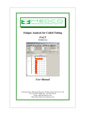
Stress Range, S1.E 041.E 031.E 021.E 011.E 00 1.E 01 1.E 02 1.E 03 1.E 04 1.E 05 1.E 06 1.E 07Fatigue Life, Cycles - NFigure 4: Low-cycle S-N Line (Avakov et al, 1993)As can be seen, within the elastic range the number of cycles would be in the order of 104 and morewhile in the plastic range the number of cycles is reduced significantly.αβAn equation of the form S aN bN will sufficiently describe the upper bound curve of figure 4.The term aNα represents the elastic range while the term bNβ represents the plastic range. Since thecoiled tubing is being used in the plastic range, the first term of the equation can be neglected. Hence,we can rewrite the equation as;S bN β. 6The power index β has a value of -½. Using empirical median life in cycles, Nm, and median fatiguestrength, Sm, found by tests, we can write an expression for the fatigue damage, λ, caused by a stresscycle as;2λ (S / S m ) 100%Nm. 7The value given in the literature for Sm is 1000 and for Nm is 130. As we have seen before, the coiledtubing goes through 2 cycles of plastic deformation on the reel and further 4 on the gooseneck. Each ofthese cycles induces axial stress, which can be calculated as follows; Over the gooseneck the axial stress, Sag, is;S ag do E2Rg. 8Where Rg is the gooseneck radius. Over the reel the axial stress, Sar, is;S ar do EDR. 9Where DR is the reel diameter.6
Effects of PressureInternal coiled tubing pressure induces further hoop (circumferential) and radial stresses. Theadditional stresses due to the internal pressure will adversely affect the coiled tubing life because theywill increase the overall stress, i.e. moving upwards on the Y-axis of figure 4. Note, however, if noaxial stress were present (no movement of coiled tubing taking place simultaneously), then the stressesdue to the internal pressure will only be within the elastic range thus having an insignificant effect onthe coiled tubing life.The additional stress component due to the internal pressure can be computed as;St 2d i2 Pid o2 d i2. 10The total stress is computed using an empirical formula and is given as;S S a Stm. 11Where m is a constant determined empirically. Equation (
coiled tubing strings without the risk of failure. Coiled tubing goes through several plastic deformation cycles through it's usage in and out of wells. The first deformation cycle takes place as the coiled tubing leaves the reel, where the coiled tubing is deformed from being bent to being straight. Next are two cycles of deformation while going through