Transcription
Tim ClaycombTI Designs – Precision: Verified DesignSingle-Supply Strain Gauge in a Bridge ConfigurationReference DesignTI Designs – PrecisionCircuit DescriptionTI Designs – Precision are analog solutions createdby TI’s analog experts. Verified Designs offer thetheory, component selection, simulation, completePCB schematic & layout, bill of materials, andmeasured performance of useful circuits. Circuitmodifications that help to meet alternate design goalsare also discussed.This strain gauge reference design accuratelymeasures the resistance of a strain gauge placed in abridge configuration. Changes in the strain gaugeresistance create a differential voltage that isamplified by an instrumentation amplifier. The bridgeexcitation voltage and instrumentation amplifierreference voltage are supplied using the REF5025.Design ResourcesTIPD170TINA-TI INA333REF5025Ask The Analog ExpertsWEBENCH Design CenterTI Designs – Precision LibraryAll Design filesSPICE SimulatorProduct FolderProduct Folder:An IMPORTANT NOTICE at the end of this TI reference design addresses authorized use, intellectual property matters andother important disclaimers and information.TINA-TI is a trademark of Texas InstrumentsWEBENCH is a registered trademark of Texas InstrumentsTIDUB00-November 2015Single-Supply Strain Gauge in a Bridge Configuration Reference DesignCopyright 2015, Texas Instruments Incorporated1
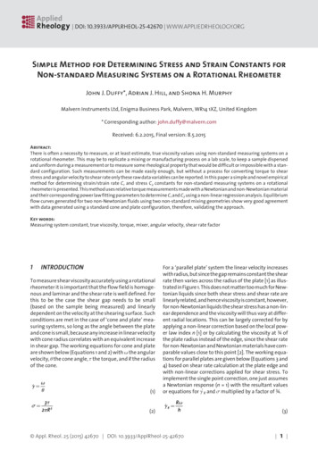
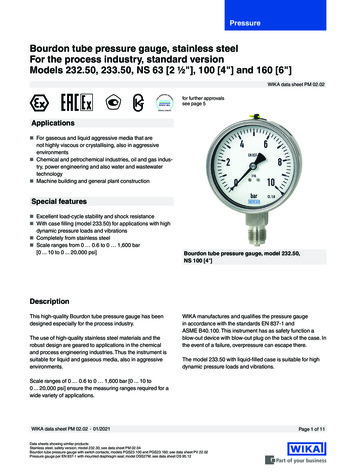
www.ti.com1Design SummaryThe design requirements are as follows: Supply Voltage: 5 V Bridge Excitation Voltage: 2.5 V Strain Gauge Nominal Resistance: 120 Ω Strain Gauge Resistance Variation: 115 Ω - 125 Ω Reference Voltage: 2.5 V Output Voltage: 225 mV to 4.72 VThe design goals and performance are summarized in Table 1. Figure 1 depicts the measured transferfunction of the design.Table 1. Comparison of Design Goals, Simulation, and Measured PerformanceSpecificationGoalCalculated (max)Calculated (typ)MeasuredTotalUncalibratedError (%FSR) 1.5%1.833%0.688%-0.953%Total CalibratedError (%FSR) 0.01%0.0072%0.0042%-0.0154%Vout (V)Output Voltage vs. Strain Gauge 26Strain Gauge Resistance (Ω)Figure 1: Measured Output Voltage vs. Strain Gauge Resistance2Single-Supply Strain Gauge in a Bridge Configuration Reference DesignCopyright 2015, Texas Instruments IncorporatedTIDUB00-November 2015
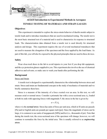
www.ti.com2Theory of Operation2.1Strain Gauge Measurement TopologyA strain gauge is a sensor whose resistance varies with applied force. The change in resistance is directlyproportional to how much strain the sensor is experiencing due to the force applied. To measure thevariation in resistance, the strain gauge is placed in a bridge configuration as shown in Figure 2.Figure 2: Strain Gauge Measurement TopologyEquation ( 1 ) shows the transfer function for the circuit show in Figure 2.Vout Vdiff G Vref(1)Where:Vref the reference voltage of the instrumentation amplifier.G the gain of the instrumentation amplifier.As the strain gauge resistance varies from its nominal value, a differential voltage, Vdiff, is produced acrossthe bridge. Equation ( 2 ) calculates the differential voltage across the bridge.Vdiff R3 R1 Rsg R2 R1 R2 R3 R1 R5 R1 R5 R2 R5 R3 Rsg R2 Rsg R3 Rsg R5 Vexcite(2)Typically, resistors, R1, R2, and R3, are set equal to the strain gauge nominal resistance so that a 0 Vdifferential voltage is produced across the bridge when the strain gauge is not experiencing strain. WithR1 R2 R3, the differential voltage across the bridge can be simplified to Equation ( 3 ).R1 Rsg R12Vdiff simple TIDUB00-November 2015 2 R1 3R5 R1 3R4 R1 2 Rsg R1 Rsg R4 Rsg R52 Vexcite(3)Single-Supply Strain Gauge in a Bridge Configuration Reference DesignCopyright 2015, Texas Instruments Incorporated3
www.ti.com2.2Measuring the Differential Bridge VoltageAn instrumentation amplifier is typically used to amplify the differential bridge voltage. Instrumentationamplifiers have very high input impedance and therefore introduce negligible error with respect to thebridge resistance. The output voltage (Vout) of the instrumentation amplifier can be calculated usingEquation ( 1 ).A reference voltage must be supplied to the instrumentation amplifier because strain gauge can increaseand decrease in resistance which produces a positive and negative differential bridge voltage. Thereference voltage should be one-half of the supply voltage. A reference voltage at mid-supply biases theoutput voltage of the instrumentation amplifier to allow differential measurements in the positive andnegative direction.2.3Common Mode ResistorsThe common mode resistors, R4 and R5, have two main functions; limit the current through the bridge andset the common mode of the instrumentation amplifier. The current through the bridge determines howlarge of a differential signal will be produced by the bridge. However, there are limitations on the currentthrough the bridge due to self-heating effects of the bridge resistors and strain gauge. There is alsotypically a maximum current specification for the strain gauge that cannot be exceeded without damagingthe strain gauge. The current through the bridge can be calculated using Equation ( 4 ).I bridge 3R1 Rsg2 R1 3R5 R1 2 Rsg R1 Rsg R5 3R4 R1 Rsg R42 Vexcite(4)Equation ( 4 ) can be simplified to Equation ( 5 ).I bridge VexciteR4 R5 Rbridge(5)Where:Rbridge the total resistance of the bridge.To ensure the instrumentation amplifier can produce the maximum output voltage swing, the commonmode of the instrumentation amplifier must be set correctly. The input common mode voltage (Vcm) can becalculated using Equation ( 6 ).Vcm 3R5 R1 2 Rsg R1 Rsg R52 R1 3R5 R1 2 Rsg R1 Rsg R5 3R4 R1 Rsg R42 Vexcite(6)Equation ( 6 ) can be simplified to Equation ( 7 ).RbridgeVcm 42 R5Rbridge R4 R5 VexciteSingle-Supply Strain Gauge in a Bridge Configuration Reference DesignCopyright 2015, Texas Instruments Incorporated(7)TIDUB00-November 2015
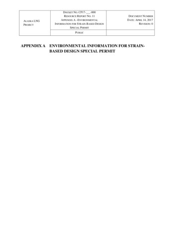
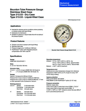
www.ti.com3Component Selection3.1Bridge Resistors (R1, R2, and R3)The bridge resistors R1, R2, and R3 are chosen to be 120 Ω to match the resistance of the stain gaugenominal resistance. Matching the bridge resistors with the strain gauge resistance produces a 0 Vdifferential bridge voltage when the strain gauge resistance is at its nominal value. The tolerances of theresistors were chosen to be 0.05% to minimize the offset and gain errors due to the bridge resistors.3.2Instrumentation AmplifierThe instrumentation amplifier chosen for this design is the INA333 for its low input offset, low input offsetvoltage drift, low input bias current, and rail-to-rail output voltage swing.3.3Common Mode Resistors (R4 and R5)R4 was chosen to be 0 Ω to allow for the maximum current through the bridge and ultimately the maximumdifferential bridge voltage. R5 is chosen to be 1.27 kΩ to place the input common mode voltage of theINA333 at approximately 2.4 V. Having a common mode of 2.4 V allows for the maximum output swing ofthe instrumentation amplifier. Figure 3 shows the output voltage vs. common mode voltage plot of theINA333; notice a common mode voltage of 1.5 V to 3.5 V produces the largest possible output voltageswing. The tool used to create Figure 3 can be downloaded here.Figure 3: Vcm vs. Vout of INA3333.4Instrumentation Amplifier GainThe gain of the instrumentation amplifier is set to 1000V/V by choosing the gain-setting resistor, Rg, to be100 Ω. A tolerance of 0.01% was chosen to minimize the gain error due to resistor tolerance. Equation ( 8 )calculates the gain of the instrumentation amplifier.G TIDUB00-November 2015Vout max Vout minVdiff max Vdiff min 4.72V 225mV 1001V / V2.22mV ( 2.27mV )(8)Single-Supply Strain Gauge in a Bridge Configuration Reference DesignCopyright 2015, Texas Instruments Incorporated5
www.ti.com3.5Bridge Excitation Voltage/Amplifier Reference VoltageThe REF5025 was chosen to supply the bridge excitation voltage and INA333 reference voltage becauseof its high initial accuracy, low noise, and low drift performance. Using a 2.5 V reference voltage for theINA333 biases the output voltage to mid-supply when a 0 V differential voltage is measured.6Single-Supply Strain Gauge in a Bridge Configuration Reference DesignCopyright 2015, Texas Instruments IncorporatedTIDUB00-November 2015
www.ti.com4Simulation and Error Calculations4.1SimulationFigure 4 shows the TINA-TI circuit used for simulation.Figure 4: TINA-TI simulation circuitFigure 5 displays the simulated output voltage for a strain gauge resistance from 115 Ω to 125 Ω. Noticewhen the strain gauge has a resistance of 120 Ω, equal to the bridge resistors, the output voltage is equalto the reference voltage of 2.5 V. When the strain gauge resistance is above 120 Ω, the output voltage isabove 2.5 V and when the strain gauge resistance is below 120 Ω, the output voltage is below 2.5 V.Figure 5: Simulation ResultsTIDUB00-November 2015Single-Supply Strain Gauge in a Bridge Configuration Reference DesignCopyright 2015, Texas Instruments Incorporated7
www.ti.com4.2Error Calculations4.2.1Errors Due to Bridge and Common Mode ResistorsThe tolerance of the bridge resistors, R1, R2, and R3, and common mode resistor, R5, create both an offsetand gain error. The majority of the offset error is due to the bridge resistors tolerance and the majority ofthe gain error is due to the common mode resistor tolerance. Equation ( 9 ) calculates the bridge differentialvoltage (Vdiff bridge). Setting R1 and R3 with a negative tolerance and R2 with a positive tolerance gives theworst-case offset error due to the bridge resistors. Setting R5 to have a negative tolerance gives the worstcase gain error due to the common mode resistors. The offset error (Voffset error) is calculated usingEquation ( 10 ). The gain error in the positive (Vgain errror pos) and negative (Vgain errror neg) direction iscalculated using Equation ( 11 ) and Equation ( 12 ), respectively. The worst case offset and gain errorreferred to the input (RTI) due to the bridge and common mode resistors is calculated to be 81.02 µV and 2.95 µV, respectively.Vdiff bridge R3 R1 Rsg R2 R1 R2 R3 R1 R5 R1 R5 R2 R5 R3 Rsg R2 Rsg R3 Rsg R5 Vexcite(9)Voffset error Vdiff tolerance@120 Vdiff ideal@120 ( 10 )Vgain error pos (Vdiff tolerance@125 Vdiff ideal@125 ) (Vdiff tolerance@120 Vdiff ideal@120 )( 11 )Vgain error neg (Vdiff tolerance@115 Vdiff ideal@115 ) (Vdiff tolerance@120 Vdiff ideal@120 )( 12 )Where:Vdiff tolerance@120Ω the bridge differential voltage with the bridge resistors maximum tolerance at astrain gauge resistance of 120 Ω.Vdiff ideal@120Ω the ideal bridge differential voltage with a strain gauge resistance of 120 Ω.Vdiff tolerance@125Ω the bridge differential voltage with the bridge resistors maximum tolerance at astrain gauge resistance of 125 Ω.Vdiff ideal@125Ω the ideal bridge differential voltage with a strain gauge resistance of 125 Ω.Vdiff tolerance@115Ω the bridge differential voltage with the bridge resistors maximum tolerance at astrain gauge resistance of 115 Ω.Vdiff ideal@115Ω the ideal bridge differential voltage with a strain gauge resistance of 115 Ω.4.2.2Errors Due to INA333The errors associated with the INA333 are due to input offset voltage, common mode rejection ratio(CMRR), gain error, and gain non-linearity. These errors are listed in Table 2.Table 2: INA333 Performance SpecificationsINA333 SpecificationTypical ValueInput Offset Voltage (µV) 10 25/GCommon Mode Rejection Ratio (dB)115Gain Error (%FSR)0.25Gain Non-Linearity (ppm)10The input offset voltage RTI (Vos µV) of the INA333 is calculated using Equation ( 13 ) and has the units ofmicrovolts.8Single-Supply Strain Gauge in a Bridge Configuration Reference DesignCopyright 2015, Texas Instruments IncorporatedTIDUB00-November 2015
www.ti.comVos V 10 2525 10 10.025 VG1000( 13 )The CMRR of the INA is specified in the product datasheet (PDS) as 115 dB, Equation ( 14 ) converts theCMRR specification into units of V/V.Vos CMRR(V / V ) 10CMRR dB / 20 10115/ 20 562341.3252V / V( 14 )The offset voltage due to CMRR of the INA333 RTI (Vos CMRR) is calculated using Equation ( 15 ).Vos CMRR(V ) (Vcm spec Vcm system ) / Vos CMRR(V / V ) (2.5V 2.4V ) 178.498nV562341.3252V / V( 15 )The gain error of the INA333 (VGE(%FSR)) is specified as 0.25 %FSR. Equation ( 16 ) converts the INA333gain error specification into units of volts.VGE (V ) VGE (% FSR) FSRinput1000.25 0.0045V 10.8 V100 ( 16 )Where:FSRinput the full-scale range of the input to the INA333.The gain non-linearity specification of the INA333 is specified in parts per million (ppm). Equation ( 17 ) andEquation ( 18 ) converts the linearity specification from ppm to volts.Vos linearity(%) Vos linearity(V ) 4.2.3Vos linearity( ppm) 10000Vos linearity(%) FSRinput max10010 0.001%10000 ( 17 )0.001 0.0055 55nV100( 18 )Total Uncalibrated ErrorThe total input referred error is calculated by taking the root sum square (RSS) of all errors associated withthe bridge and INA333. Equation ( 19 ) calculates the total error of the system in units of volts. Equation ( 20) converts the total error to a percentage of the full scale range. The total RTI error of the system iscalculated to be 1.833 %FSR. The total RTI error calculated in Equation ( 20 ) assumes a worst casescenario for the bridge resistors tolerance. However, this is unlikely to occur. Using typical tolerancevalues the total RTI error is calculated to be 0.688 %FSR. The majority of the total error is due to the offseterror of the bridge.VTotal Error(V ) Voffset error Vgain error pos Vos V Vos CMRR(V ) VGE (V ) Vos linearity(V )22VTotal Error(% FSR) 4.2.42VTotal Error(V ) 100FSRinput 22282.4603 V 100 1.833% FSR0.0045V( 19 )( 20 )Total Calibrated ErrorThe total calibrated error is calculated by taking the RSS of errors associated with the CMRR and gainnon-linearity of the INA333. Equation ( 21 ) calculates the total calibrated error in units of volts. Equation ( 22) converts the total calibrated error to a percentage of the full scale range. The total RTI calibrated error ofthe system is calculated to be 0.004 %FSR.VTotal Cal Error(V ) Vos CMRR(V ) Vos linearity(V ) 178.498nV 2 55nV 2 186.779nV2TIDUB00-November 20152( 21 )Single-Supply Strain Gauge in a Bridge Configuration Reference DesignCopyright 2015, Texas Instruments Incorporated9
www.ti.comVTotal Cal Error(% FSR) VTotal Cal Error(V ) 100 186.779nV 100 0.0042% FSRFSRinput0.0045V10 Single-Supply Strain Gauge in a Bridge Configuration Reference DesignCopyright 2015, Texas Instruments Incorporated( 22 )TIDUB00-November 2015
www.ti.com5PCB DesignThe PCB schematic and bill of materials can be found in Appendix A.5.1PCB LayoutFigure 6 shows the PCB layout for the design. The traces for the bridge and common mode resistors werekept as short and balanced as possible to minimize the possibility of a differential voltage in the signalchain due to trace impedance mismatch. The terminal block, J1, was placed on the bottom of the PCB toallow for a close connection of R4 and R5. Finally, the gain setting resistor, Rg, was placed as close to thepins of U1 as possible to minimize stray capacitance and trace impedance. General layout guidelines,such as, placing decoupling capacitors close to the devices as possible and pouring a solid ground plane,were also used.Figure 6: PCB LayoutTIDUB00-November 2015Single-Supply Strain Gauge in a Bridge Configuration Reference Design 11Copyright 2015, Texas Instruments Incorporated
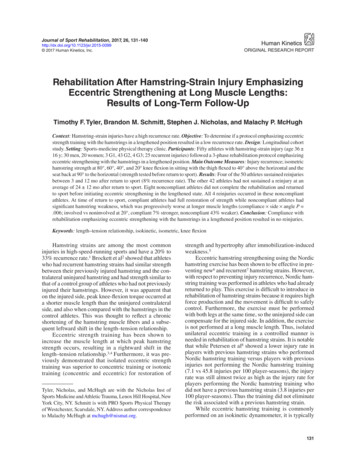
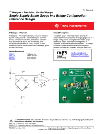
www.ti.com6Verification & Measured Performance6.1Output Voltage vs. Strain Gauge ResistanceFigure 7 shows the measured output voltage of the INA333 vs. strain gauge resistance. The data wascollected by placing different values of resistors in the terminal block, J1, to represent the strain gaugeresistance. Each resistor used was accurately measured before being placed in the terminal block. Highaccurate low drift resistors were used to prevent a change in resistance due to heating while handling theresistors when placing them into the terminal block or from self-heating due to the bridge current.Output Voltage vs. Strain Gauge Resistance54.54Vout (V)3.532.521.510.50114116118120122124126Strain Gauge Resistance (Ω)Figure 7: Output Voltage vs. Strain Gauge Resistance6.2Uncalibrated ErrorThe total full scale uncalibrated error is calculated using Equation ( 23 ).Error% FSR Vout measured Vout idealFSRoutput 100( 23 )Where:Vout ideal the ideal output voltageVout measured the measured output voltageFSRoutput the ideal full scale output voltage rangeTo calculate the ideal output voltage, the resistor used to simulate the strain gauge resistance wasmeasured, recorded, and then used to calculate the ideal differential bridge voltage. The ideal values forthe bridge resistors and common mode resistors were used. The ideal differential bridge voltage iscalculated using Equation ( 3 ). Equation ( 1 ) is used to calculate the ideal output voltage.12 Single-Supply Strain Gauge in a Bridge Configuration Reference DesignCopyright 2015, Texas Instruments IncorporatedTIDUB00-November 2015
www.ti.comFigure 8 shows the total full scale uncalibrated error. Notice the majority of the error is an offset errorcaused from the resistors in the bridge.Total Full Scale Uncalibrated Error-0.8-0.82114116118120122124126Error (%FSR)-0.84-0.86-0.88%FSR Error-0.9-0.92-0.94-0.96Strain Gauge Resistance (Ω)Figure 8: Total Full Scale Uncalibrated Error6.3CalibrationA 2-point calibration was performed to remove errors due to offset voltage, gain error, componenttolerance, etc. The data points chosen for calibration were with a maximum and minimum strain gaugeresistance of 115 Ω and 125 Ω, respectively. To perform a calibration, a gain correction factor, α, and anoffset correction factor, β, must first be calculated using Equation ( 24 ) and Equation ( 25 ), respectively.Table 2 displays the data points used for calibration.Table 3: Data Points for CalibrationVoutStrain Gauge Resistance 115 ΩStrain Gauge Resistance 125 ΩMeasuredIdealMeasuredIdeal0.1924346 V0.229689358 V4.708435 V4.751455036 V Vout ideal@125 Vout ideal@115 Vout measured@125 Vout measured@115 Vout measured@115 Vout ideal@115 ( 24 )( 25 )Using Equation ( 24 ) and Equation ( 25 ), α is calculated to be 1.001277, and β is calculated to be -0.03701.Equation ( 26 ) was used to calculate the calibrated output voltage.Vout calibrated (Vout measured ) TIDUB00-November 2015( 26 )Single-Supply Strain Gauge in a Bridge Configuration Reference Design 13Copyright 2015, Texas Instruments Incorporated
www.ti.comFigure 8 shows the total full-scale error after calibration. The non-linearity shown in Figure 9 is greater thanthe non-linearity specification of the INA333; some of this error can be attributed to noise in the system.Assuming a best-case scenario and using the input voltage noise specification in the INA333 datasheet of50 nV/ Hz at 10 Hz, the output noise peak-to-peak is calculated to be 1.31 mVpp which is 0.029 %FSR ofthe output. Equation ( 27 ) calculates the output noise peak-to-peak. Equation ( 28 ) converts the peak-topeak output noise to a percentage of the full-scale range.VnVVnoise pp 6.6 G Vnoise BWn 1.57 6.6 1000 50 10 Hz 1.57 1.31mVppVHzVnoise pp 100 1.31mVpp 100Vnoise % FSR 0.029% FSRFSRoutput4.5V( 27 )( 28 )Where:Vnoise the input voltage noise of the INA333.BW n bandwidth of the INA333.Total Full Scale Error After Calibration0.0150.01%FSR Error0.0050114116118120122124126-0.005%FSR Error Calibrated-0.01-0.015-0.02Strain Gauge Resistance (Ω)Figure 9: Total Full Scale Error After Calibration14 Single-Supply Strain Gauge in a Bridge Configuration Reference DesignCopyright 2015, Texas Instruments IncorporatedTIDUB00-November 2015
www.ti.com7Modifications7.1Strain GaugeA strain gauge with a different nominal resistance can be used, typical strain gauge nominal resistancesare, 120 Ω, 350 Ω, 1000 Ω, and 3000 Ω. If a different nominal resistance is used, the bridge resistors mustbe chosen to match the nominal resistance of the strain gauge.7.2Common Mode ResistorsThe common mode resistors, R4 and R5, can be increased to reduce the current consumption of the circuit,or decreased to create a larger differential bridge voltage. If a larger differential bridge voltage is present,the gain of the instrumentation amplifier must be adjusted such that the output voltage does not exceedthe output voltage swing of the device. Furthermore, R4 and R5, must be adjusted such that the commonmode voltage of the device is not violated and the maximum strain gauge current is not exceeded.7.3AmplifierOther instrumentation amplifiers can be used to measure the differential bridge voltage, such as, theINA188 for a low drift solution, the INA827 for applications that require a higher bandwidth or the INA122for a lower power solution with higher gain.8About the AuthorTimothy Claycomb is an Analog Applications Engineer in the Precision Linear group at Texas Instruments.He earned his B.S. in Electrical Engineering from Michigan State University in 2013.TIDUB00-November 2015Single-Supply Strain Gauge in a Bridge Configuration Reference Design 15Copyright 2015, Texas Instruments Incorporated
www.ti.com9Acknowledgements & References1.A. Kay, Operational Amplifier Noise: Techniques and Tips for Analyzing and Reducing Noise.Elsevier, 2012.2.The Strain Gauge. Available: e3/strain2.html3.Bridge Measurement Systems Section 5 (SLYP163)The author would like to thank Collin Wells for his technical contribution during this design.16 Single-Supply Strain Gauge in a Bridge Configuration Reference DesignCopyright 2015, Texas Instruments IncorporatedTIDUB00-November 2015
www.ti.comAppendix A.A.1 Electrical SchematicFigure A-1: Electrical SchematicTIDUB00-November 2015Single-Supply Strain Gauge in a Bridge Configuration Reference Design 17Copyright 2015, Texas Instruments Incorporated
www.ti.comA.2 Bill of MaterialsFigure A-2: Bill of Materials18 Single-Supply Strain Gauge in a Bridge Configuration Reference DesignCopyright 2015, Texas Instruments IncorporatedTIDUB00-November 2015
IMPORTANT NOTICE FOR TI REFERENCE DESIGNSTexas Instruments Incorporated ("TI") reference designs are solely intended to assist designers (“Buyers”) who are developing systems thatincorporate TI semiconductor products (also referred to herein as “components”). Buyer understands and agrees that Buyer remainsresponsible for using its independent analysis, evaluation and judgment in designing Buyer’s systems and products.TI reference designs have been created using standard laboratory conditions and engineering practices. TI has not conducted anytesting other than that specifically described in the published documentation for a particular reference design. TI may makecorrections, enhancements, improvements and other changes to its reference designs.Buyers are authorized to use TI reference designs with the TI component(s) identified in each particular reference design and to modify thereference design in the development of their end products. HOWEVER, NO OTHER LICENSE, EXPRESS OR IMPLIED, BY ESTOPPELOR OTHERWISE TO ANY OTHER TI INTELLECTUAL PROPERTY RIGHT, AND NO LICENSE TO ANY THIRD PARTY TECHNOLOGYOR INTELLECTUAL PROPERTY RIGHT, IS GRANTED HEREIN, including but not limited to any patent right, copyright, mask work right,or other intellectual property right relating to any combination, machine, or process in which TI components or services are used.Information published by TI regarding third-party products or services does not constitute a license to use such products or services, or awarranty or endorsement thereof. Use of such information may require a license from a third party under the patents or other intellectualproperty of the third party, or a license from TI under the patents or other intellectual property of TI.TI REFERENCE DESIGNS ARE PROVIDED "AS IS". TI MAKES NO WARRANTIES OR REPRESENTATIONS WITH REGARD TO THEREFERENCE DESIGNS OR USE OF THE REFERENCE DESIGNS, EXPRESS, IMPLIED OR STATUTORY, INCLUDING ACCURACY ORCOMPLETENESS. TI DISCLAIMS ANY WARRANTY OF TITLE AND ANY IMPLIED WARRANTIES OF MERCHANTABILITY, FITNESSFOR A PARTICULAR PURPOSE, QUIET ENJOYMENT, QUIET POSSESSION, AND NON-INFRINGEMENT OF ANY THIRD PARTYINTELLECTUAL PROPERTY RIGHTS WITH REGARD TO TI REFERENCE DESIGNS OR USE THEREOF. TI SHALL NOT BE LIABLEFOR AND SHALL NOT DEFEND OR INDEMNIFY BUYERS AGAINST ANY THIRD PARTY INFRINGEMENT CLAIM THAT RELATES TOOR IS BASED ON A COMBINATION OF COMPONENTS PROVIDED IN A TI REFERENCE DESIGN. IN NO EVENT SHALL TI BELIABLE FOR ANY ACTUAL, SPECIAL, INCIDENTAL, CONSEQUENTIAL OR INDIRECT DAMAGES, HOWEVER CAUSED, ON ANYTHEORY OF LIABILITY AND WHETHER OR NOT TI HAS BEEN ADVISED OF THE POSSIBILITY OF SUCH DAMAGES, ARISING INANY WAY OUT OF TI REFERENCE DESIGNS OR BUYER’S USE OF TI REFERENCE DESIGNS.TI reserves the right to make corrections, enhancements, improvements and other changes to its semiconductor products and services perJESD46, latest issue, and to discontinue any product or service per JESD48, latest issue. Buyers should obtain the latest relevantinformation before placing orders and should verify that such information is current and complete. All semiconductor products are soldsubject to TI’s terms and conditions of sale supplied at the time of order acknowledgment.TI warrants performance of its components to the specifications applicable at the time of sale, in accordance with the warranty in TI’s termsand conditions of sale of semiconductor products. Testing and other quality control techniques for TI components are used to the extent TIdeems necessary to support this warranty. Except where mandated by applicable law, testing of all parameters of each component is notnecessarily performed.TI assumes no liability for applications assistance or the design of Buyers’ products. Buyers are responsible for their products andapplications using TI components. To minimize the risks associated with Buyers’ products and applications, Buyers should provideadequate design and operating safeguards.Reproduction of significant portions of TI information in TI data books, data sheets or reference designs is permissible only if reproduction iswithout alteration and is accompanied by all associated warranties, conditions, limitations, and notices. TI is not responsible or liable forsuch altered documentation. Information of third parties may be subject to additional restrictions.Buyer acknowledges and agrees that it is solely responsible for compliance with all legal, regulatory and safety-related requirementsconcerning its products, and any use of TI components in its applications, notwithstanding any applications-related information or supportthat may be provided by TI. Buyer represents and agrees that it has all the necessary expertise to create and implement safeguards thatanticipate dangerous failures, monitor failures and their consequences, lessen the likelihood of dangerous failures and take appropriateremedial actions. Buyer will fully indemnify TI and its representatives against any damages arising out of the use of any TI components inBuyer’s safety-critical applications.In some cases, TI components may be promoted specifically to facilitate safety-related applications. With such components, TI’s goal is tohelp enable customers to design and create their own end-product solutions that meet applicable functional safety standards andrequirements. Nonetheless, such components are subject to these terms.No TI components are authorized for use in FDA Class III (or similar life-critical medical equipment) unless authorized officers of the partieshave executed an agreement specifically governing such use.Only those TI components that TI has specifically designated as military grade or “enhanced plastic” are designed and intended for use inmilitary/aerospace applications or environments. Buyer acknowledges and agrees that any military or aerospace use of TI components thathave not been so designated is solely at Buyer's risk, and Buyer is solely responsible for compliance with all legal and regulatoryrequirements in connection with such use.TI has specifically designated certain components as meeting ISO/TS16949 requirements, mainly for automotive use. In any case of use ofnon-designated products, TI will not be responsible for any failure to meet ISO/TS16949.IMPORTANT NOTICEMailing Address: Texas Instruments, Post Office Box 655303, Dallas, Texas 75265Copyright 2015, Texas Instruments Incorporated
through the bridge due to self-heating effects of the bridge resistors and strain gauge. There is also typically a maximum current specification for the strain gauge that cannot be exceeded without damaging the strain gauge. The current through the bridge can be calculated using Equation ( 4 ). excite sg sg