Transcription
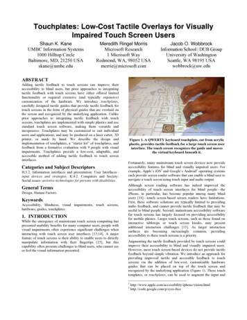
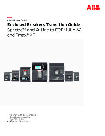
Data AcquisitionTexas Instruments IncorporatedUsing resistive touch screens forhuman/machine interfaceBy Rick Downs (Email: downs rick@ti.com)Applications Engineering Manager, Data Acquisition ProductsIntroductionFigure 1. Resistive touch screenTouch-screen interfaces are effective in many informationappliances, in personal digital assistants (PDAs), and asgeneric pointing devices for instrumentation and controlapplications. Getting the information from a touch screeninto a microprocessor can be challenging. This articleintroduces the basics of how resistive touch screens workand how to best convert these analog inputs into usabledigital data. Issues such as settling time, noise filtering,and speed trade-offs are addressed.TransparentConductor (ITO)Bottom SideTransparentConductor (ITO)Top SideX Conductive BarY SilverInkResistive touch screensResistive touch screens consist of a glass or acrylic panelthat is coated with electrically conductive and resistivelayers made with indium tin oxide (ITO) (see Figure 1).The thin layers are separated by invisible spacers.Resistive screens are generally the most affordable typeof touch screen, which explains their success in high-useapplications like PDAs and Internet appliances. Althoughclarity is not as good as with other touch-screen types,resistive screens are very durable. The only concern is thatthe resistive layers can be damaged by a very sharp object.The two most popular resistive architectures use 4-wireor 5-wire configurations, as shown in Figure 2 (the 5-wireconfiguration uses the second layer as a wiper contact, notshown here). The circuits determine location in twocoordinate-pair dimensions, although a third dimension canbe added for measuring pressure in 4-wire xas Instruments (TI) offers specialized analog-todigital converters (ADCs) for interfacing to these twopopular resistive touch screens. Since the majority ofapplications use 4-wire touch screens, the rest of thisarticle concentrates on this architecture, although thesame advice applies to the 5-wire screens and theADS7845, TI’s 5-wire touch-screen controller.Figure 2. Touch-screen circuit configurations4-wire5-wire5Analog Applications Journal3Q 2005www.ti.com/aajAnalog and Mixed-Signal Products
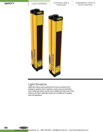
Data AcquisitionTexas Instruments IncorporatedResistive touch-screen controllersUsing a differential or ratiometric measurement technique like this provides much more accurate results,particularly in systems with noisy power supplies or wherethe touch screen is located a significant distance awayfrom the controller.When a position is measured on a 4-wire touch screen,voltage is applied across the screen in the Y direction;and a touch presses the layers together, where a voltagecan be read from one of the X electrodes. The contactmade as a result of the touch creates a voltage divider atthat point, so the Y coordinate can be determined; theprocess then repeats with the X direction being driven,and a reading is taken from one of the Y electrodes.A touch-screen controller is simply an ADC that hasbuilt-in switches to control which electrodes are drivenand which electrodes are used as the input to the ADC.The ADC can often be operated with different referencemodes: single-ended or differential.Touch-screen settling timeSingle-ended configurationIn a single-ended configuration, the ADC reference is supplied between a reference input (VREF) and ground. Veryoften, VREF is actually the power supply voltage.The ADC output is then a ratio of the input signal to theVREF voltage. Since the touch screen is a voltage divider,this may seem sensible. However, there are several possible errors that may show up due to the driver switches,such as gain and offset errors from temperature, voltagedrops in the switches, etc.If the reference voltage is not the power supply, thenpower-supply variations could cause errors, since thepower supply is the voltage placed across the screen; and,while it varies, the reference voltage will not.Variations in touch-screen impedance can also causegain or offset errors.Differential configurationIn the differential configuration, the ADC’s voltage reference is taken directly across the touch screen, eliminatingdriver variations, power-supply changes, and even changesin the touch-screen impedance. The output of the ADC isstill the ratio of the input to VREF. VREF is now the voltageacross the screen, and the output is a true reflection ofthe position of the touch on the screen.When the touch panel is pressed or touched, there are twomechanisms that will affect the voltage level at the contactpoint. These two mechanisms will cause the voltage acrossthe touch panel to “ring” and then to settle (decay) downslowly to a stable dc value.The two mechanisms are:1. Mechanical bouncing caused by vibration of the toplayer sheet of the touch panel when the panel is pressed.2. The charging of the parasitic capacitance between thetop and bottom layer sheets of the touch panel and atthe input of the ADC that occurs when the drivers turnon, and inductive effects from the leads connecting thepanel to the drivers in the controller.Difference between single-ended and differential modesIn both single-ended and differential modes, the ADCacquires (samples) the input analog voltage from thetouch panel for some time, tACQ (see Figure 3). The inputvoltage has to settle within tACQ in order for the ADC tocapture the correct voltage.Turning the drivers on causes the touch panel’s voltageto rise rapidly and then settle to the final value, as shownin Figure 3. To acquire the correct value for conversion,the acquisition must be complete when the touch panelhas completely settled. There are two ways of accomplishing this.One method (shown in Figure 3) uses the ADC in singleended mode and a relatively slow clock. A slow clockextends the acquisition time, since it extends the clockperiods used for acquisition. The drivers turn on at thebeginning of the first of three clock periods (for simplecontrollers like the ADS7843, ADS7846, TSC2003, andTSC2046). The panel must then settle completely duringFigure 3. Timing diagram of single-ended-mode operation for TSC2046Signal fromTouch PanelSlow ClockDCLKDINX/Y SwitchesSER/DFR HighSA2A1A0ModeSER/DFRPD0PD0Control Byte AOnt CONVtACQ6Analog and Mixed-Signal Productswww.ti.com/aaj3Q 2005Analog Applications Journal
Data AcquisitionTexas Instruments Incorporatedthe following two clock cycles, so that at the end of thethird clock cycle, the acquired voltage is accurate.The second method (shown in Figure 4) uses the differential mode and a much faster clock rate. Control byte Bturns the drivers on and, as before, the touch panel’s voltagerises rapidly and begins to settle. In this case, a conversionis done, and then a second conversion is begun, by sending control byte C. If control bytes B and C are the same,the internal X/Y switch of the ADC will not turn off aftercompleting a conversion for control byte B. Thus, thetouch panel voltage will be settled by the time the conversion from control byte C begins, and this conversion willbe accurate. This method requires that the conversionresult from control byte B be discarded, as it will not beaccurate since its acquisition period occurred when thetouch panel voltage was still ringing.An advantage to using the second method is the potential for power savings. After the end of conversion forcontrol byte C, the controller can go into power-downmode and wait for the next sampling period. In the slowclock case, the next sample period may have to comeimmediately after the current conversion, leaving no timefor power down.Using a fast clock in single-ended mode (Figure 5)would not be of any help, because the drivers turn offbetween conversions. This results in the touch panel’svoltage rising at the beginning of each conversion, whichnever gives the touch panel a chance to settle.Figure 4. Using a fast clock in differential mode for TSC2046Signal fromTouch PanelFast ClockDCLKDINPower DownSSPower DownControl Byte CControl Byte BDOUT00tACQX/Y SwitchesSER/DFR HighOnOnX/Y SwitchesSER/DFR LowtCONVOnFigure 5. Using a fast clock in single-ended modeSignal fromTouch PanelFast ClockDCLKDINPower DownSSPower DownControl Byte CControl Byte BDOUT00tACQX/Y SwitchesSER/DFR HighOnX/Y SwitchesSER/DFR LowOntCONVOn7Analog Applications Journal3Q 2005www.ti.com/aajAnalog and Mixed-Signal Products
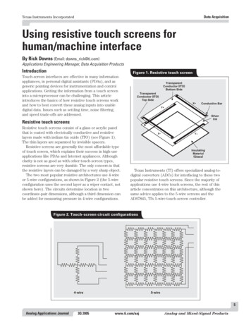
Data AcquisitionTexas Instruments Incorporatedsame process can be used for taking Z-coordinate readingsif touch pressure is also to be measured.The Z-axis measurement for touch pressure is used inapplications such as signature capture, where the pressureinformation is important for recognizing the authenticityof a signature. However, even in conventional X-Y applications, using the Z-axis measurement can be helpful indetermining whether a touch data point is valid. Using thismeasurement can help prevent spurious readings that mayoccur due to the mechanical bouncing of the touch screenplates, simply because readings where the pressure is toolight are not accepted. A complete description of the Z-axismeasurement process can be found in the datasheets fortouch-screen controllers with this capability.Making the ADC results usable fora human interfaceSince several measurements for one coordinate pair arebeing taken, the designer has the opportunity to do someprocessing on this data, like averaging. This will help prevent spurious readings that may make dealing with thehuman interface difficult.Touch-screen acquisition flowchartFigure 6 shows a typical flowchart for a touch screen. Inits idle state, the touch-screen controller’s pen interrupt(PENIRQ) line is held high. When a touch occurs on thescreen, the PENIRQ line is driven low, signaling the hostprocessor that it needs to start taking coordinate readings.The host will then turn on the X drivers, wait for settlingto occur, and then take several readings of the X coordinate. The host will then turn off the X drivers and turn onthe Y drivers. After waiting again for the screen to settle,the host will take several readings of the Y coordinate. TheData-averaging algorithmThe averaging algorithm reduces noise resulting fromcontact bounce during use of the touch screen. SuccessiveX and Y samples are tested to determine if their valuesFigure 6. Touch-screen acquisition flowchartScreen TouchController IssuesPENIRQNoHost Turns OnX , X– DriversHost Turns OnY , Y– DriversHost Turns OnY , X– DriversIs Panel VoltageStabilizationDone?Is Panel VoltageStabilizationDone?Is Panel VoltageStabilizationDone?Host Detects andServicesPENIRQNoNoYesYesYesRead X CoordinateRead Y CoordinateRead Z CoordinatesIs DataAveragingDone?Is DataAveragingDone?Is DataAveragingDone?NoNoNoYesYesYesIs ScreenStill Touched?YesIs ScreenStill Touched?YesYesNoNoNoIs ScreenStill Touched?Done8Analog and Mixed-Signal Productswww.ti.com/aaj3Q 2005Analog Applications Journal
Data AcquisitionTexas Instruments Incorporateddiffer by no more than a certain range. If one or moresamples falls outside this range, the samples are discardedand the process is restarted. This is continued until successive X samples (then Y samples) fall within the range.The average of these values is used as the X and Y coordinates, respectively.Once independent X and Y samples are obtained, coordinate pairs are sampled to eliminate the effects of noise. If asample does not fall within an internal range, all X and Ycoordinate pairs are discarded and the independent X and Ysequence is restarted. Once acceptable coordinate pairs havebeen obtained, an average coordinate pair is determined.The entire process just described can be done by theprocessor or by some of the newer, intelligent controllerslike TI’s TSC2200, TSC2301, or TSC2101. These devicestake care of the settling-time issues and other touchscreen interface problems previously described; they alsorelieve the host CPU from the tasks of reading and writingover the serial interface so often. These intelligent devicescan be programmed to respond to a touch, take a complete set of coordinate readings, average several readings,and then—only when this entire process is complete—interrupt the host processor. The host then does only onereading of all coordinates and need not do any furtheraveraging or noise reduction.These highly integrated devices come paired with keypad controllers (TSC2200) or audio codecs (TSC2301,TSC2101) to provide complete human/machine interfacecontrollers in a single package.ReferenceFor more information related to this article, you can download an Acrobat Reader file at www-s.ti.com/sc/techlit/litnumber and replace “litnumber” with the TI Lit. # forthe materials listed below.Document TitleTI Lit. #1. Skip Osgood, CK Ong, and Rick Downs,“Touch Screen Controller Tips,”Application Report . . . . . . . . . . . . . . . . . . . . . . . .sbaa036Related Web numberReplace partnumber with ADS7843, ADS7845, ADS7846,TSC2003, TSC2046, TSC2101, TSC2200, or TSC23019Analog Applications Journal3Q 2005www.ti.com/aajAnalog and Mixed-Signal Products
IMPORTANT NOTICETexas Instruments Incorporated and its subsidiaries (TI) reservethe right to make corrections, modifications, enhancements,improvements, and other changes to its products and services atany time and to discontinue any product or service without notice.Customers should obtain the latest relevant information beforeplacing orders and should verify that such information is currentand complete. All products are sold subject to TI's terms andconditions of sale supplied at the time of order acknowledgment.TI warrants performance of its hardware products to thespecifications applicable at the time of sale in accordance with TI'sstandard warranty. Testing and other quality control techniques areused to the extent TI deems necessary to support this warranty.Except where mandated by government requirements, testing ofall parameters of each product is not necessarily performed.TI assumes no liability for applications assistance or customerproduct design. Customers are responsible for their products andapplications using TI components. To minimize the risksassociated with customer products and applications, customersshould provide adequate design and operating safeguards.TI does not warrant or represent that any license, either express orimplied, is granted under any TI patent right, copyright, mask workright, or other TI intellectual property right relating to anycombination, machine, or process in which TI products or servicesare used. Information published by TI regarding third-partyproducts or services does not constitute a license from TI to usesuch products or services or a warranty or endorsement thereof.Use of such information may require a license from a third partyunder the patents or other intellectual property of the third party, or alicense from TI under the patents or other intellectual property of TI.Reproduction of information in TI data books or data sheets ispermissible only if reproduction is without alteration and isaccompanied by all associated warranties, conditions, limitations,and notices. Reproduction of this information with alteration is anunfair and deceptive business practice. TI is not responsible orliable for such altered documentation.Resale of TI products or services with statements different from orbeyond the parameters stated by TI for that product or servicevoids all express and any implied warranties for the associated TIproduct or service and is an unfair and deceptive businesspractice. TI is not responsible or liable for any such statements.Following are URLs where you can obtain information on otherTexas Instruments products and application solutions:ProductsAmplifiersData ConvertersDSPInterfaceLogicPower otiveBroadbandDigital controlMilitaryOptical NetworkingSecurityTelephonyVideo & ti.com/wirelessTI Worldwide Technical SupportInternetTI Semiconductor Product Information Center Home Pagesupport.ti.comTI Semiconductor KnowledgeBase Home Pagesupport.ti.com/sc/knowledgebaseProduct Information CentersAmericasPhoneInternet/Email 1(972) 644-5580Faxsupport.ti.com/sc/pic/americas.htm 1(972) 927-6377Europe, Middle East, and AfricaPhoneBelgium (English) 32 (0) 27 45 54 32Netherlands (English) 31 (0) 546 87 95 45Finland (English) 358 (0) 9 25173948Russia 7 (0) 95 7850415France 33 (0) 1 30 70 11 64Spain 34 902 35 40 28Germany 49 (0) 8161 80 33 11Sweden (English) 46 (0) 8587 555 22Israel (English)1800 949 0107United Kingdom 44 (0) 1604 66 33 99Italy800 79 11 37Fax (49) (0) 8161 80 iaPhoneInternationalDomesticAustraliaChinaHong KongIndonesiaKoreaMalaysiaFaxInternet c/pic/japan.htmwww.tij.co.jp/pic 886-2-23786800Toll-Free upport.ti.com/sc/pic/asia.htmNew -Free 011905Safe Harbor Statement: This publication may contain forwardlooking statements that involve a number of risks anduncertainties. These “forward-looking statements” are intendedto qualify for the safe harbor from liability established by thePrivate Securities Litigation Reform Act of 1995. These forwardlooking statements generally can be identified by phrases suchas TI or its management “believes,” “expects,” “anticipates,”“foresees,” “forecasts,” “estimates” or other words or phrasesof similar import. Similarly, such statements herein that describethe company's products, business strategy, outlook, objectives,plans, intentions or goals also are forward-looking statements.All such forward-looking statements are subject to certain risksand uncertainties that could cause actual results to differmaterially from those in forward-looking statements. Pleaserefer to TI's most recent Form 10-K for more information on therisks and uncertainties that could materially affect future resultsof operations. We disclaim any intention or obligation to updateany forward-looking statements as a result of developmentsoccurring after the date of this publication.Trademarks: All trademarks are the property of theirrespective owners.Mailing Address:Texas InstrumentsPost Office Box 655303Dallas, Texas 75265 2005 Texas Instruments IncorporatedSLYT209A
Resistive touch screens Resistive touch screens consist of a glass or acrylic panel that is coated with electrically conductive and resistive layers made with indium tin oxide (ITO) (see Figure 1). The thin layers are separated by invisible spacers. Resistive screens are generally the most affordable type of touch screen, which explains their .