Transcription
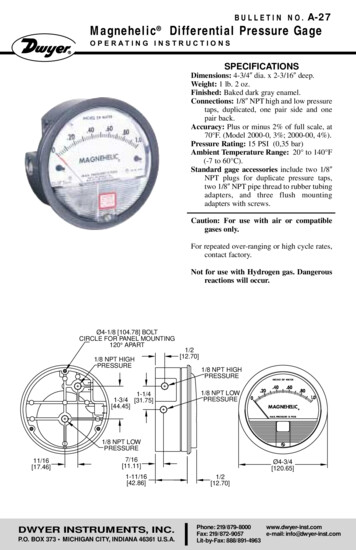
BULLETIN NO.Magnehelic A-27Differential Pressure GageO P E R AT I N G I N S T R U C T I O N SSPECIFICATIONSDimensions: 4-3/4 dia. x 2-3/16 deep.Weight: 1 lb. 2 oz.Finished: Baked dark gray enamel.Connections: 1/8 NPT high and low pressuretaps, duplicated, one pair side and onepair back.Accuracy: Plus or minus 2% of full scale, at70 F. (Model 2000-0, 3%; 2000-00, 4%).Pressure Rating: 15 PSI (0,35 bar)Ambient Temperature Range: 20 to 140 F(-7 to 60 C).Standard gage accessories include two 1/8 NPT plugs for duplicate pressure taps,two 1/8 NPT pipe thread to rubber tubingadapters, and three flush mountingadapters with screws.Caution: For use with air or compatiblegases only.For repeated over-ranging or high cycle rates,contact factory.Not for use with Hydrogen gas. Dangerousreactions will occur.Ø4-1/8 [104.78] BOLTCIRCLE FOR PANEL MOUNTING120 APART1/8 NPT HIGHPRESSURE1-1/41-3/4 [31.75][44.45]1/2[12.70]1/8 NPT HIGHPRESSURE1/8 NPT LOWPRESSURE1/8 NPT YER INSTRUMENTS, INC.P.O. BOX 373 MICHIGAN CITY, INDIANA 46361 U.S.A.Ø4-3/4[120.65]1/2[12.70]Phone: 219/879-8000www.dwyer-inst.comFax: 219/872-9057e-mail: info@dwyer-inst.comLit-by-Fax: 888/891-4963
MAGNEHELIC INSTALLATION1.Select a location free from excessive vibration and where the ambient temperaturewill not exceed 140 F. Also, avoid directsunlight which accelerates discoloration ofthe clear plastic cover. Sensing lines my berun any necessary distance. Long tubinglengths will not affect accuracy but will increase response time slightly. Do not restrict lines. If pulsating pressures or vibration cause excessive pointer oscillation,consult the factory for ways to provide additional damping.2. All standard Magnehelic gages are calibrated with the diaphragm vertical andshould be used in that position for maximum accuracy. If gages are to be used inother than vertical position, this should bespecified on the order. Many higher rangegages will perform within tolerance in otherpositions with only rezeroing. Low rangeModel 2000-00 and metric equivalentsmust be used in the vertical position only.3. Surface MountingLocate mounting holes, 120 apart on a 41/8 dia. circle. Use No. 6-32 machinescrews of appropriate length.4. Flush MountingProvide a 4-9/16 dia. opening in panel.Insert gage and secure in place with No. 632 machine screws of appropriate length,with adapters, firmly secured in place. Tomount gage on 1-1/4 -2 pipe, order optional A-610 pipe mounting kit.5. To zero the gage afterinstallationSet the indicating pointer exactly on thezero mark, using the external zero adjustscrew on the cover at the bottom. Note thatthe zero check or adjustment can only bemade with the high and low pressure tapsboth open to atmosphere.OperationPositive Pressure:Connect tubing fromsource of pressure to either of the two highpressure ports. Plug the port not used. Ventone or both low pressure ports to atmosphere.Negative Pressure: Connect tubing fromsource of vacuum or negative pressure toeither of the two low pressure ports. Plugthe port not used. Vent one or both highpressure ports to atmosphere.Differential Pressure: Connect tubingfrom the greater of two pressure sources toeither high pressure port and the lower toeither low pressure port. Plug both unusedports.When one side of the gage is vented indirty, dusty atmosphere, we suggest an A331 Filter Vent Plug be installed in the openport to keep inside of gage clean.A. For portable use of temporary installation use 1/8 pipe thread to rubber tubingadapter and connect to source of pressurewith rubber or Tygon tubing.B. For permanent installation, 1/4 O.D., orlarger, copper or aluminum tubing is recommended. See accessory bulletin S-101for fittings.Ordering Instructions:When corresponding with the factory regarding Magnehelic gage problems, besure to include model number, pressurerange, and any special options. Field repairis not recommended; contact the factoryfor repair service.
MAINTENANCECaution: If bezel binds when installing, lubricate threads sparingly with light oil ormolybdenum disulphide compound.Warning: Attempted field repair may voidyour warrenty. Recalibration or repairby the user is not recommended. Forbest results, return gage to the factory.Ship prepaid to:Dwyer Instruments, Inc.Attn: Repair Dept.102 Indiana Highway 212Michigan City, IN 46360Maintenance: No lubrication or periodicservicing is required. Keep case exterior andcover clean. Occasionally disconnect pressure lines to vent both sides of gage to atmosphere and re-zero. Optional vent valves,(bulletin S-101), should be used in permanent installations.Calibration Check: Select a second gage ormanometer of known accuracy and in an appropriate range. Using short lengths of rubber or vinyl tubing, connect the high pressure side of the Magnehelic gage and the testgage to two legs of a tee. Very slowly applypressure through the third leg. Allow a fewseconds for pressure to equalize, fluid todrain, etc., and compare readings. If accuracy unacceptable, gage may be returned tofactory for recalibration. To calibrate in thefield, use the following procedure.Calibration:1. With gage case, held firmly, loosen bezel,by turning counterclockwise. To avoid damage, a canvas strap wrench or similar toolshould be used.2. Lift out plastic cover and “O” ring.3. Remove scale screws and scale assembly.Be careful not to damage pointer.4. The calibration is changed by moving theclamp. Loosen the clamp screw(s) and moveslightly toward the helix if gage is readinghigh, and away if reading low. Tightenclamp screw and install scale assembly.5. Place cover and O-ring in position. Makesure the hex shaft on inside of cover is properly engaged in zero adjust screw.6. Secure cover in place by screwing bezeldown snug. Note that the area under thecover is pressurized in operation and therefore gage will leak if not properly tightened.7. Zero gage and compare to test instrument.Make further adjustments as necessary. Copyright 2001 Dwyer Instruments, Inc.Trouble Shooting Tips: Gage won’t indicate or is sluggish.1. Duplicate pressure port not plugged.2. Diaphragm ruptured due to overpressure.3. Fittings or sensing lines blocked,pinched, or leaking.4. Cover loose or “O”ring damaged, missing.5. Pressure sensor, (static tips, Pitot tube,etc.) improperly located.6. Ambient temperature too low. For operation below 20 F, order gage with low temperature, (LT) option. Pointer stuck-gage can’t be zeroed.1. Scale touching pointer.2. Spring/magnet assembly shifted andtouching helix.3. Metallic particles clinging to magnetand interfering with helix movement.4. Cover zero adjust shaft broken or notproperly engaged in adjusting screw.We generally recommend that gages needing repair be returned to the factory. Partsused in various sub-assemblies vary fromone range of gage to another, and use of incorrect components may cause improperoperation. After receipt and inspection, wewill be happy to quote repair costs beforeproceeding.Consult factory for assistance on unusualapplications or conditions.Use with air or compatible gases only.Printed in U.S.A. 4/01DWYER INSTRUMENTS, INC.P.O. BOX 373 MICHIGAN CITY, INDIANA 46361 U.S.A.FR# 12-440212-00 Rev. 3Phone: 219/879-8000www.dwyer-inst.comFax: 219/872-9057e-mail: info@dwyer-inst.comLit-by-Fax: 888/891-4963
MAINTENANCECaution: If bezel binds when installing, lubricate threads sparingly with light oil ormolybdenum disulphide compound.Warning: Attempted field repair may voidyour warrenty. Recalibration or repairby the user is not recommended. Forbest results, return gage to the factory.Ship prepaid to:Dwyer Instruments, Inc.Attn: Repair Dept.102 Indiana Highway 212Michigan City, IN 46360Maintenance: No lubrication or periodicservicing is required. Keep case exterior andcover clean. Occasionally disconnect pressure lines to vent both sides of gage to atmosphere and re-zero. Optional vent valves,(bulletin S-101), should be used in permanent installations.Calibration Check: Select a second gage ormanometer of known accuracy and in an appropriate range. Using short lengths of rubber or vinyl tubing, connect the high pressure side of the Magnehelic gage and the testgage to two legs of a tee. Very slowly applypressure through the third leg. Allow a fewseconds for pressure to equalize, fluid todrain, etc., and compare readings. If accuracy unacceptable, gage may be returned tofactory for recalibration. To calibrate in thefield, use the following procedure.Calibration:1. With gage case, held firmly, loosen bezel,by turning counterclockwise. To avoid damage, a canvas strap wrench or similar toolshould be used.2. Lift out plastic cover and “O” ring.3. Remove scale screws and scale assembly.Be careful not to damage pointer.4. The calibration is changed by moving theclamp. Loosen the clamp screw(s) and moveslightly toward the helix if gage is readinghigh, and away if reading low. Tightenclamp screw and install scale assembly.5. Place cover and O-ring in position. Makesure the hex shaft on inside of cover is properly engaged in zero adjust screw.6. Secure cover in place by screwing bezeldown snug. Note that the area under thecover is pressurized in operation and therefore gage will leak if not properly tightened.7. Zero gage and compare to test instrument.Make further adjustments as necessary. Copyright 2001 Dwyer Instruments, Inc.Trouble Shooting Tips: Gage won’t indicate or is sluggish.1. Duplicate pressure port not plugged.2. Diaphragm ruptured due to overpressure.3. Fittings or sensing lines blocked,pinched, or leaking.4. Cover loose or “O”ring damaged, missing.5. Pressure sensor, (static tips, Pitot tube,etc.) improperly located.6. Ambient temperature too low. For operation below 20 F, order gage with low temperature, (LT) option. Pointer stuck-gage can’t be zeroed.1. Scale touching pointer.2. Spring/magnet assembly shifted andtouching helix.3. Metallic particles clinging to magnetand interfering with helix movement.4. Cover zero adjust shaft broken or notproperly engaged in adjusting screw.We generally recommend that gages needing repair be returned to the factory. Partsused in various sub-assemblies vary fromone range of gage to another, and use of incorrect components may cause improperoperation. After receipt and inspection, wewill be happy to quote repair costs beforeproceeding.Consult factory for assistance on unusualapplications or conditions.Use with air or compatible gases only.Printed in U.S.A. 4/01DWYER INSTRUMENTS, INC.P.O. BOX 373 MICHIGAN CITY, INDIANA 46361 U.S.A.FR# 12-440212-00 Rev. 3Phone: 219/879-8000www.dwyer-inst.comFax: 219/872-9057e-mail: info@dwyer-inst.comLit-by-Fax: 888/891-4963
BULLETIN NO.Manometro Diferencial MagnehelicA-27 I N S T R U C C I O N E S Y L I S TA D E PA R T E SESPECIFICACIONESDimensiones: diám. 120,65 mm x 55,6 prof.Peso: 509 g.Terminación: esmalte horneado gris oscuro.Conexiones: 1/8 NPT para alta y baja presión,duplicadas (atrás, a los lados).Exactitud: 2% de fondo de escala a 21 CMod. 2000-0 3%; Mod. 2000-00 4%Presión máxima: 15 PSI (0,35 bar)Temperatura: -7 a 60 CAccesorios: Tapones 1/8 NPT para las conexiones duplicadas, dos adaptadores de rosca1/8 NPT a tubo de goma; y tres adaptadores para montaje al ras y tornillos.Atencion: solo para uso con aire o gasescompatibles.Para indicaciones de sobrerango repetidas uotras contacte a Fábrica.Precaución para uso con hidrogeno: el imándel instrumento puede en presencia dehidrógeno liberar gases tóxicos y explosivos. Para este caso, consulte a fábrica.Ø4-1/8 [104.78] BOLTCIRCLE FOR PANEL MOUNTING120 APART1/8 NPT HIGHPRESSURE1-1/41-3/4 [31.75][44.45]1/2[12.70]1/8 NPT HIGHPRESSURE1/8 NPT LOWPRESSURE1/8 NPT YER INSTRUMENTS, INC.P.O. BOX 373 MICHIGAN CITY, INDIANA 46361 U.S.A.Ø4-3/4[120.65]1/2[12.70]Phone: 219/879-8000www.dwyer-inst.comFax: 219/872-9057e-mail: info@dwyer-inst.comLit-by-Fax: 888/891-4963
INSTALACIÓN1. Seleccione un lugar libe de exceso de vibraciones, y donde la temperatura ambienteno supere los 60 C. Evite luz solar directa,para evitar decoloración de la cubierta plástica. Las conexiones de proceso puedentener cualquier longitud sin afectar la exactitud, pero pueden extender el tiempo de respuesta del instrumento. Si hay pulsación depresión o vibración, consulte a fábrica sobremedios de amortiguación.2. Los MAGNEHELIC han sido calibradoscon el diafragma vertical, y deben ser usadosen esas condiciones. Para otras posiciones,se debe especificar en la orden de provisión.Los de rango elevado pueden ser usados endiversas posiciones, pero se debe reajustar elcero. Los modelos de la serie 2000-00 yequivalentes métricos deben ser usados soloverticalmente.3. Montaje en SuperficiePerfore tres orificios separados 120 sobreuna circunferencia de 105 mm de diám. ysostenga el instrumento con tres tornillos6-32 de long. apropiada.4. Montaje al RasPerfore un circulo de 115 mm de diám. en elpanel, y sostenga el instrumento mediantelos. Para montaje sobre caño, ordene eladaptador A-610 apto para caños de 32 a 50mm de diám.5. Puesta a Cero Después deInstalarDeje las conexiones de presión abiertas aatmósfera y ajuste a cero desde tornillo delpanel frontal.OperacionPresión Positiva: Conecte la tubería desdela fuente de presión a cualquiera de las dosconexiones de alta presión (HIGH), bloqueando la no usada; Las conexiones de baja(LOW) presión pueden dejarse uno o los dosabiertos a la atmósfera.Presión Negativa: Repita el procedimientoanterior, conectado en este caso las conexiones de baja presión (LOW). Deje las otrasconexiones abiertas.Presión diferencial: Conecte el tubo correspondiente a la presión más positiva alcualquiera de los conectores de alta presión(HIGH) bloqueando el no usado, y la másbaja presión o presión negativa (vacío) alconector de baja presión (LOW). Puede usarse cualquier conector de cada par, dejandosiempre uno bloqueado. Si se deja unaconexión abierta a la
sure side of the Magnehelic gage and the test gage to two legs of a tee. Very slowly apply pressure through the third leg. Allow a few seconds for pressure to equalize, fluid to drain, etc., and compare readings. If accu-racy unacceptable, gage may be returned to factory for recalibration. To calibrate in the field, use the following procedure. Calibration: 1. With gage case, held firmly, loosen bezel,