Transcription
George Craft, Thermo Fisher ScientificKey WordsAbstractRTCA, DO-160G, Cable Induction,Multiple Burst, Single Stroke,Multiple Stroke, Pin InjectionThe effects of lightning on commercial aircraft are highly regulated worldwide today. Therehave been several articles written [1, 2] concerning Lightning Induced TransientSusceptibility requirements. The RTCA/DO-160G standard [3] section 22 is applicable toequipment installed on metallic and composite aircraft. This article will cover theapplication of transient impulses onto the interconnecting wiring and cable bundles usedon those aircraft. There are several test types discussed in section 22 that will be usedhere. Specific emphasis will be for waveform 3 (Wf3), 1MHz used during the multipleburst, multiple stroke, and PIN injection testing.WF3 1MHz CABLE INDUCTIONCable induction for single stroke, multiple stroke, and multiple burst are test methodswhere the transient impulse waveform is coupled onto the inter-connecting wires andcables under test. This is accomplished using an inductive coupling device such as a 1:1transformer (coupling clamp). The coupling clamp used in this example is made fromnickel zinc ferrite. This material was selected due to its frequency response at or above1MHz. The cable under test becomes the secondary of the coupling transformer. Energyis coupled from the primary onto the cable and into the Equipment Under Test (EUT). Tocapture these waveforms, the user will need a digital storage oscilloscope capable of5GS/s with 20M points or better. Some of the test types have multiple irregularly spacedwaveforms that are spread over a period of 1 ½ seconds. Setting up the oscilloscopeproperly before test execution is critical to accurately capturing these waveform patterns.The voltage and current monitor probes used to collect these data are required to becapable of high voltage and current with a wide enough bandwidth to be used for 10MHzwaveforms.Wh i te Pa perApplications of RTCA/DO-160G toCommercial Avionics Equipment
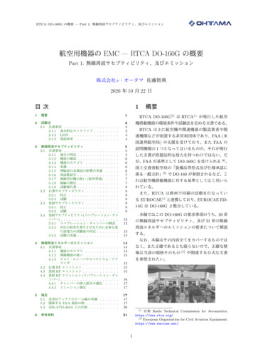
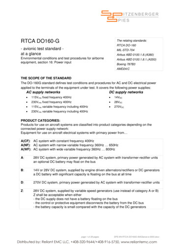
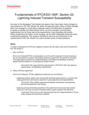
2Table 22-5: Test Levels for Cable BundleMultiple Burst TestsTypically, the Procuring Officer (PO) of the airframe manufacturer will specify the test type,waveform, and test level of the transient impulse (L1 increasing to L5) . The location of theparticular avionics equipment on or within the aircraft will determine the severity level to beapplied. The more protected the location, such as a shielded enclosure well inside theaircraft, the lower the test requirement (L1, for example). Conversely, for avionicsequipment closer to the outside of the aircraft use the higher test level (L5, for example).Likewise, mission critical avionics require this higher test level. See Table 22-5 for leveldetails. The wave shape of Waveform 3 is shown in Figure 22-3: it is an exponentiallydecaying sinusoid with a frequency of 1MHz. The defining characteristics of the waveformare its zero to peak voltage amplitude, the ringing frequency (1/T), and the ratio of the fifthpeak amplitude to the first peak amplitude. This is typically referred to as the waveform Q(5th pk/1st pk 25%). The same waveform parameters are used to define the currentwaveform during PIN injection testing. Cable induction is a method used to apply any ofthe DO-160G specified waveforms onto the interconnecting wires or cable bundles. Thegenerator output is measured and verified using the calibration loop on the injectiontransformer. The waveform verification set-up is shown in Figure 22-16 and is used duringthese tests. This article demonstrates applying the Wf3 1MHz waveform for each test typediscussed.
3Figure 22-3: Voltage/Current Waveform3Figure 22-8: Multiple Burst Application
4Figure 22-16: Typical GeneratorPerformance Verification Setup for CableInduction TestsFigure 22-17: Typical Cable InductionTest Setup
5Figure 1: Wf3 Multiple Burst1MHz Test BenchWF3 1MHz MULTIPLE BURSTThe waveform timing for multiple burst testing is shown in Figure 22-8. There are threeburst packets of 20 impulses each, spaced randomly over a period of 1 ½ seconds. Eachof the transient impulses has exactly the same waveform characteristics shown in Figure22-3. Figure 1 illustrates the bench set-up used for the multiple burst test shown in Figure22-17 of DO-160G. 120V, 60Hz AC is applied via the output side of the two lineimpedance stabilization networks (LISNs) and routed to the EUT input. The one meterpower cable is raised 50mm above the ground plane interconnecting the LISNs and theEUT with non-conductive foam blocks. The calibrated Pearson current monitor probe(4535) is located between 5 and 15cm from the EUT output. The cable under testcontains 4 core wires that are connected to the support equipment, in this case, 72 solidstate LEDs. There is also a shield that is bonded to the ground plane at both endscovering the core wires. The injection transformer is located between 5 and 50cm fromthe current monitor probe. Note that the test cable is also 50mm above the ground plane.
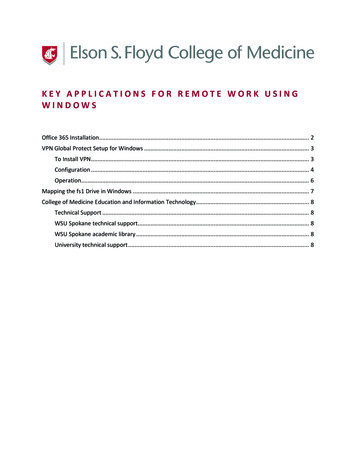
6Select the multiple burst test type from the generator user interface. Next, select the1MHz waveform. Set up the injection transformer and test cables then adjust the outputvoltage to the desired transient level (L1 – 5). Verify the output waveform as shown inFigure 22-3 with the timing intervals of Figure 22-8. The generator output is adjusted toreach either the test voltage level or limit current level specified in Table 22-5 on thecable under test. The screen shots below show that the current limit of level 5 isreached first. Figure 2 shows the 3 irregularly spaced burst packets and the 20irregularly spaced voltage and current transients are of equal amplitude. Figure 3 showsone each of the 1MHz voltage and current waveforms. These same settings arerepeated every 3 seconds for a time period of 5 minutes in each polarity. The equipmentmust operate normally throughout the entire test period and after completion with nodegradation of performance. Store this data and the test set-up pictures for inclusion inthe test report.Figure 2: 20 Irregular TransientsFigure 3: Level 5 Current LimitThis completes the multiple burst cable induction test requirement.WF3 1MHz COMBINED SINGLE STROKE AND MULTIPLE STROKEThe multiple stroke test type consists of a first stroke of a certain amplitude followed by13 subsequent strokes. In our demonstration, the first transient of multiple stroke has thehigher peak amplitude given in Table 22-4. All of the subsequent strokes are 50% of thefirst transient also indicated in the table. The bench set-up is the same as shown inFigure 1 for multiple burst. The only difference is multiple stroke is selected from the userinterface and then applied to the injection transformer. The requirements for multiplestroke first and subsequent strokes are shown in Table 22-4 for all waveforms. Thegenerator performance verification test set-up is the same as shown for multiple burst inFigure 22-16. The cable induction test set-up is the same as shown in Figure 22-17 for
7Figure 22-4: Test and Limit Levels forCable Bundle Multiple Stroke TestsAs stated, the bench set-up is the same as shown in Figure 1 using the injectiontransformer, current monitor, LISN’s, EUT, and support equipment. The generator outputis first adjusted to the voltage amplitude specified for the first transient. Next, thegenerator output is adjusted for the voltage level of the thirteen subsequent transients at50% of the first. Once the waveform verification is complete, the generator is programmedfor five positive applications at the levels determined in the calibration process. It is thenadjusted for five negative applications to the cable under test. Many POs allow for thesingle stroke waveform to be included as the first stroke to speed up the test time (andreduce test cost). The Single Stroke test requirements are shown in Table 22-3 ofDO-160G but not included here. In this case, the 1MHz single stroke requirement and firststroke requirement are the same. This isn’t necessarily true for other waveform types, forexample: Wf4, and Wf5A/B.Figure 22-7: Multiple Stroke Application
8The calibration results are shown in Figure 8. The test results for voltage and current areshown in Figure 9.Figure 8: Wf3 Voltage Multiple Stroke CalibrationFigure 9: Wf3 Voltage and Current on CableThis completes the multiple stroke cable induction test requirement.WF3 1MHz PIN INJECTIONPIN Injection is a test method where the transient impulse waveform is directly coupledfrom the generator output to the connector pins and case ground. This is considered adestructive test as the impulses are injected directly into the EUT. The five levels areshown in Table 22-2 for Wf3, Wf4, and Wf5a. The level required is specified by the PObased on the equipments location within the aircraft and electro-magnetic protectionprovided.Figure 22-2: Generator Setting Levels forPin Injection
9Figure 22-10: Pin Injection CalibrationSetup, Signal Pins & Power Pins - DirectInjection MethodFor signal and power pins, the waveform calibration set-up is shown in Figure 22-10, andthe test set-up is shown in Figure 22-13. There are several other choices for the PIN testset-up indicated and discussed in DO-160G not shown here.
10Figure 22-13: Pin Injection Test Setup,Signal Pins & Power Pins - DirectInjection MethodThe generator output impedance (Zo 25 Ohms 10%) for the 1MHz waveform isverified. Measure the open circuit voltage (OCV) and the short circuit current (SCI) thenapply Ohm’s Law: Zo OCV/SCI. The impedance is measured at the end of a two metergenerator output cable. A one foot shorting wire is used to measure SCI.Select the PIN Injection type from the user interface. Next select the 1MHz waveform andadjust the set voltage for the desired transient impulse level. Verify the output waveformsfor OCV and SCI as shown in Figure 22-3 using the values listed in Table 22-2. Store thiscalibration data and set-up pictures for inclusion in the test report.
11Figure 4: Wf3 PIN Injection L5 CurrentLimitFigure 4 shows the powered PIN Injection bench set-up. The resulting calibrationwaveforms for voltage and current are shown in Figures 5 & 6. The limit current is reachedas shown in Figure 7 on this cable. Note that the coupling capacitor is connected in serieswith the power pin and the generator output. The capacitor is used to isolate the generator output from the input power applied. The user must verify normal operation after testcompletion. PIN testing usually consists of five positive and five negativeapplications of the test impulse waveform at the required level.
12Figure 5: Wf3 PIN OCV CalibrationFigure 6: Wf3 PIN SCI CalibrationFigure 7: Wf3 PIN Level 5 Current LimitThis completes the PIN injection requirementCONCLUSIONThis has been a quick overview of the various 1Mz waveform test types. Each type isperformed for the EUT with all support equipment configured as installed with powerapplied. The measured waveforms for the cable bundles acquired during the illustratedtests demonstrate the application of these tests. Each test type covered also refers to therelevant specifications. In addition to the Wf3, 1MHz waveform discussed above, there aremany more waveforms that may be required by the PO. For the specific types of testrequirements, refer to the RTCA/DO160G standard. The acceptance of the EUT andsupporting equipment is contingent upon the PO authorizing and witnessing the tests andaccepting the data.There are many other specifications for avionics equipment not discussed here. Almostevery aircraft manufacturer has its own variations to those mentioned above formDO-160G, for example, Boeing (D6-16050), Airbus (ABD0100.1.2). Most use similarwaveforms, test types, and coupling methods with some form of variation.
ReferencesFundamentals of DO160F, Section 22: Lightning Induced Transient Susceptibility By: Louis A.Feudi and Robert Given January 01, 2010 InCompliance Magazine[2]New EMC Requirements for Commercial Avionics: RTCA/DO160G By: Erik J. Borgstrom May05,2011 InCompliance Magazine[3]RTCA/DO160G, “Environmental Conditions and Test Procedures for Airborne Equipment”section 22 RTCA, Incorporated, December 8, 2010Thermo Fisher Scientific,San Jose, CA USA is ISO Certified.thermoscientific.com 2014 Thermo Fisher Scientific Inc. All rights reserved. All trademarks are the property of Thermo Fisher Scientific Inc. and its subsidiaries. Specifications,terms and pricing are subject to change. Not all products are available in all countries. Please consult your local sales representative for details.Africa-Other 27 11 570 1840Australia 61 2 8844 9500Austria 43 1 333 50 34 0Belgium 32 53 73 42 41Canada 1 800 530 8447China 86 10 8419 3588Denmark 45 70 23 62 60Europe-Other 43 1 333 50 34 0Finland /Norway/Sweden 46 8 556 468 00France 33 1 60 92 48 00Germany 49 6103 408 1014India 91 22 6742 9434Italy 39 02 950 591Japan 81 45 453 9100Latin America 1 608 276 5659Middle East 43 1 333 50 34 0Netherlands 31 76 579 55 55South Africa 27 11 570 1840Spain 34 914 845 965Switzerland 41 61 716 77 00UK 44 1442 233555USA 1 800 532 4752Wh i te Pa per[1]
The RTCA/DO-160G standard section 22 is applicable to equipment installed on metallic and composite aircraft. This article will cover the application of transient impulses onto the interconnecting wiring and cable bundles used on those aircraft. There are several test types discussed in section 22 that will