Transcription
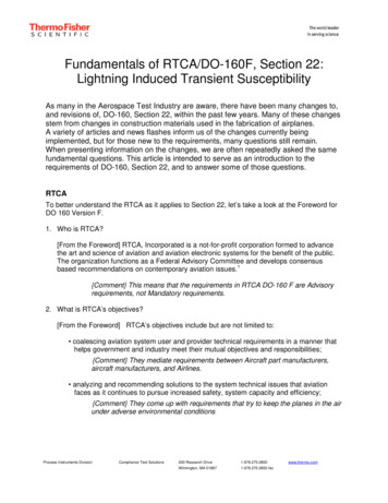
Fundamentals of RTCA/DO-160F, Section 22:Lightning Induced Transient SusceptibilityAs many in the Aerospace Test Industry are aware, there have been many changes to,and revisions of, DO-160, Section 22, within the past few years. Many of these changesstem from changes in construction materials used in the fabrication of airplanes.A variety of articles and news flashes inform us of the changes currently beingimplemented, but for those new to the requirements, many questions still remain.When presenting information on the changes, we are often repeatedly asked the samefundamental questions. This article is intended to serve as an introduction to therequirements of DO-160, Section 22, and to answer some of those questions.RTCATo better understand the RTCA as it applies to Section 22, let’s take a look at the Foreword forDO 160 Version F.1. Who is RTCA?[From the Foreword] RTCA, Incorporated is a not-for-profit corporation formed to advancethe art and science of aviation and aviation electronic systems for the benefit of the public.The organization functions as a Federal Advisory Committee and develops consensusbased recommendations on contemporary aviation issues.1{Comment} This means that the requirements in RTCA DO-160 F are Advisoryrequirements, not Mandatory requirements.2. What is RTCA’s objectives?[From the Foreword] RTCA’s objectives include but are not limited to: coalescing aviation system user and provider technical requirements in a manner thathelps government and industry meet their mutual objectives and responsibilities;{Comment} They mediate requirements between Aircraft part manufacturers,aircraft manufacturers, and Airlines. analyzing and recommending solutions to the system technical issues that aviationfaces as it continues to pursue increased safety, system capacity and efficiency;{Comment} They come up with requirements that try to keep the planes in the airunder adverse environmental conditionsProcess Instruments DivisionCompliance Test Solutions200 Research Drive1.978.275.0800Wilmington, MA 018871.978.275.0850 faxwww.thermo.com
developing consensus on the application of pertinent technology to fulfill user andprovider requirements, including development of minimum operational performancestandards for electronic systems and equipment that support aviation; and{Comment} They get both airplane manufacturers and Component manufacturersto agree on a minimum operational performance standard while the product isbeing stressed (immunity) assisting in developing the appropriate technical material upon which positions for theInternational Civil Aviation Organization and the International TelecommunicationsUnion and other appropriate international organizations can be based. 1{Comment} Worldwide Organizations adopt these requirementsas their positions on issues that arise.3. How important is RTCA’s standards?[From the Foreword] The organization’s recommendations are often used as the basis forgovernment and private sector decisions as well as the foundation for many FederalAviation Administration technical Standard Orders. Since RTCA is not an officialagency of the United States Government, its recommendations may not be regardedas statements of official government policy unless so enunciated by the U.S.government organization or agency having statutory jurisdiction over any matters towhich the recommendations relate. 1{Comment} When an aircraft manufacturer ( Boeing, Airbus, DeHavilland,Embraer, Fairchild, General Dynamics, Goodyear, Grumman, GulfstreamAmerican, etc.) is deciding on purchasing criteria for its Tier one, two and threevendor parts, it can use any or all of the requirements in the standard as part ofits buying criteria. That means almost all of the electronics incorporated intoan airplane need to meet some part of this standard.4. Who else uses these standards?[From the Foreword] These standards were coordinated by RTCA SC-135 with theEuropean Organisation for Civil Aviation Equipment (EUROCAE) Working Groups (WGs) 14and 31. EUROCAE concurs with RTCA on the environmental conditions and testprocedures set forth herein. When approved by EUROCAE, this document will be identifiedjointly as RTCA DO-160E/EUROCAE ED-14E.1{Comment} The Europeans have similar if not identical requirements, when thestandard is adopted as RTCA DO-160E/EUROCAE ED-14ESAESAE International is a global technology information and standards-setting resource for theaerospace, automotive, and commercial vehicle industries. In addition to standardsdevelopment and publication, SAE holds annual and biennial conferences and tradeshows,periodic industry seminars, student Collegiate Design competitions, all focused on all facets oftransportation.2
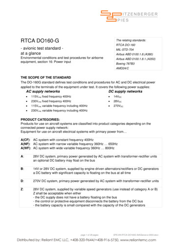
SAE Aerospace is a sub group of SAE International. Their focus is on writing AerospaceStandards (AS),which apply to missile, airframe, ground support equipment, propulsion,propeller and accessory equipment; Aerospace Recommended Practices (ARP), which providerecommendations for engineering design and provide background information and research tosupport those recommendations; and Aerospace information Reports (AIR), which containgenerally accepted industry engineering data and information.AE-2 is the SAE Lightning Committee established by the Aerospace Council of SAE. They draftand publish the recommended requirements for Indirect Lightning Strikes, based largely onindustry and SAE research and knowledge. These requirements are very often adopted intoRTCA by the RTCA SC-135 subcommittee, who is responsible for the content of DO-160.The fundamental document that defined the environment and test waveforms used in DO-160,Section 22, and accounted for the lightning data and analysis necessary to support theserequirements, is SAE ARP5412, “Aircraft Lightning Environment and Related Test Waveforms”,originally published in 1999, and revised to Revision A in 2005. This document explains wherethe concepts of Multistroke, Multi Burst and the current test waveforms originated.Change in requirements over the past few yearsMany airplane components have to keep working under environmental stress conditions. One ofthose conditions is lightning. So many airplane manufacturers specify Section 22 as one of therequirements for critical systems, like guidance, radar, communications, engine control, heatand air controls, etc.We sometimes think of avionics as being the navigation and communications equipment, but italso includes engine controls, servo motor controllers for control surfaces like ailerons, rudderand flaps, landing gear controls, radar, even satellite TV, Wi-Fi, and entertainment systems.Revisions E and F of DO 160 are driven by the use of composite materials used for airframeconstruction on recent planes like the Boeing 787 Dreamliner and Airbus A380 (Figure 1).Figure 1. Current and intended uses for composite materials in the construction of airplanes3
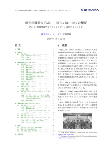
Carbon Fiber (CF), also known as graphite fiber, or carbon graphite, is a material composed ofultra-thin fibers (0.005-0.010mm diameter) of aligned crystalline Carbon atoms (see Figure 2).The crystalline alignment makes the fiber extremely strong for its size. Thousands of fibers aretwisted together to form a yarn, which is often woven into a fabric material. The fiber, combinedwith a polymer, and heated through various processes, forms a composite material that isextremely strong for its lightweight construction. This lightweight property makes the use ofCarbon Fiber Composite (CFC) very attractive to the aerospace industry, where weight/thrustratios are critical for operation, maneuverability, and fuel efficiency.Figure 2. A single carbon filament (bottom left to top right) laid across a human hair.Prior to CFC materials, the airframe and most other parts of the airplane were made of metal.Thus, if a lightning strike occurred at the nose of the plane, during takeoff for instance, thelightning would travel outside the plane to the tail, exit the surface of the plane, and continue toground. The solid metal construction of the airframe acted as a “Faraday cage”, with anextremely low impedance path. This reduced coupling of voltages and currents on the internalwiring of the plane, which usually was routed along the side of the plane, between the inside ofthe outer skin and the interior bulkhead. This also greatly reduced the susceptibility of the“mission critical” components located in the plane.CFC materials, however, don’t conduct lightning currents the way metal airframes do. As aresult, the increased impedance of the outer skin as a path for the lightning increases thepossibility of higher voltages and currents coupling directly onto internal cables and into theavionics equipment on the aircraft.Multi Stroke, Multi Burst and ARP5412 revision AFor the newly initiated, DO-160F currently calls out 6 individual waveforms. Understanding whythese waveforms were incorporated into DO-160 comes from referencing the previouslymentioned Aerospace Recommended Practice (ARP) 5412 rev. A. Under the scope of thedocument, the “standardized external current waveforms have in turn been used to derivestandardized transient voltage and current waveforms which can be expected to appear on thecable bundles and at equipment interfaces. The test waveforms are considered to be adequatefor the demonstration of compliance for the protection of an aircraft and its systems against thelightning environment.” 24
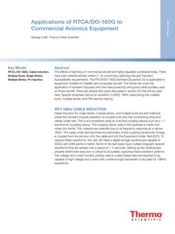
ARP5412 rev A (hereafter referred to as ARP5412) devotes an entire section to the descriptionof lightning and the variety of forms that lightning can occur. Lightning flashes are thedischarging of strong electric fields, or charge centers, within cumulonimbus clouds(Cumulonimbus clouds can form alone, in clusters, or along a cold front in a squall line. Theycreate lightning through the heart of the cloud). There are three (3) types of lightning flasheswhich may occur: Flashes between cloud regions of opposite polarity within the same cloud called intracloud dischargesFlashes between cloud regions of opposite polarity in different clouds called inter clouddischargesFlashes from clouds to ground or the reverse (in instances of high ground locations likemountains and towers)When a negative cloud to ground flash occurs, the discharge process starts with the formationof an 1-10m wide ionized column that travels in zigzag steps toward the earth. The leader mayform branches on the way down to the ground. When the leader gets close to the ground, itcauses buildup of high fields near trees and buildings. These then send up leaders to meet thetip of the downward leader. When they meet, a return stroke is initiated, which retraces anddischarges the leader channel, resulting in a bright flash and high current pulse. After the initialreturn stroke, subsequent strokes can occur from higher regions of the cloud through thedownward leader stroke. These subsequent strokes are usually of lower amplitude than theinitial return stroke.This is the idealized basis for the Multi Stroke Test parameters of DO-160, section 22. Anillustration from the standard is shown in Figure 3. The initial stroke is the highest amplitude ofthe multi Stroke application, with subsequent strokes (up to 14) at a lower but repeatedamplitude.Figure 3. Multi Stroke Application of a Waveform5
Inter- and Intra- cloud discharges behave differently than cloud to ground (and vice-versa)discharges. Most of the data recorded for inter- and intra- cloud discharges come frominstrumented aircraft employed in the USA and France to record the characteristics of thesetypes of flashes. Although cloud flashes are less severe than flashes to the ground, it was notedthat the rise time of the cloud flashes were significantly shorter (less than 0.4 us) and oftenoccurred in grouped pulses during the initial attachment and final detachment phases of thedischarges. These short duration, lower amplitude initial and final phases are the basis for theMulti Burst application of Waveform 3. An illustration of the Multiburst Waveform set is shown inIllustration 4. One burst is normally composed of 20 pulses.Figure 4. Multiburst Waveform Set6
Waveforms 1, 2, 3, 4, 5A and 5BWe now jump to section 7 of ARP5412, which describes the idealized transient waveformsintended for verification of adequate protection of systems and equipment from indirect lightningeffects. This section states that there are multiple mechanisms that can induce lightningtransients inside the plane from the external lightning environment, but broadly divides them into2 categories: Aperture Coupling and Resistive Coupling.Actual induced transients are complex waveforms that result from both coupling methods, butfor test purposes, they have been kept separate. ARP5412 states that magnetic fieldspenetrating through apertures (electromagnetically transparent openings) will induce:1. a current waveshape in conductors or shields terminated to the structure through lowimpedances at each end.,(Figure 5)Figure 5. Waveform 1 – Current, Double exponential 6.4us X 69us (to 50%)2. a voltage waveshape in loops existing between cables and the structure (Figure 6)Figure 6. Waveform 2 – Voltage, Double exponential 100ns X 6.4us (at zero crossing)7
3. damped oscillatory voltage and current waveforms resulting from excited resonances oncoupled interior cables. 1MHz and 10 MHz frequencies representing long and short cablelengths, respectively. (Figure 7)Figure 7. Waveform 3 – Voltage/Current, Ringing wave, sine or cosine 1MHz and 10MHzResistive Coupling will produce:1. voltages in conductors within shields due to shield current and shield transfer impedance(Figure 8) andFigure 8. Waveform 4 – Voltage, Double Exponential 6.4us x 69us (to 50%)8
2. voltages produced by loops existing between cables and the airframe structure (resultingfrom variances in voltage from the endpoint locations of the cable at different locationson the airframe) and voltages resulting from di
Fundamentals of RTCA/DO-160F, Section 22: Lightning Induced Transient Susceptibility As many in the Aerospace Test Industry are aware, there have been many changes to, and revisions of, DO-160, Section 22, within the past few years. Many of these changes stem from changes in construction materials used in the fabrication of airplanes.File Size: 911KBPage Count: 12