Transcription
Virtual Prototyping of a Brushless Permanent Magnet AC MotorElectromagnetic and Thermal Design using CAD SoftwareBruno Ricardo da Fonseca MarquesInstituto Superior TécnicoLisbon, PortugalBruno.f.marques@ist.utl.ptAbstract — This work’s aim is to describe theelectromagnetic and thermal design of a brushless permanentmagnet AC motor to be applied on a formula studentprototype car, FST05e, from Projecto FST Novabase. It s aBattery Electric Vehicle (BEV) designed to participate inFormula Student events. The challenge is to create a machinewith high power density and fulfill the team goals. In all trialsof competition the motor is pushed to the limits, testingacceleration, autocross, endurance, and fuel economy. Themain project goal is to achieve a lightweight motor with areduced moment of inertia, as well as keeping it cost efficient.In an iterative way to achieve the power required with lessweight, it was used CAD software to make the machine selectromagnetic and thermal design. The first one wasdeveloped with PC-BDC software from SPEED while thesecond one was developed with MOTOR CAD software fromMotor Design Ltd . To do FEA, PC-FEA software fromSPEED was used.This work describes the electromagnetic and thermaldesign process, both with the use of analytical formulations,based on lumped circuit models, and numerical analysis usingFEA. The duty cycles for all trials in competition are analyzedto verify the thermal machine behavior. Performance charts,thermal limits and efficiency maps of the machine are alsostudied using MOTOR LAB software.At the end, the design obtained exceeds even the teamexpectations.Keywords— PM AC Machine; Design PM Machine; RadialFlux PM Machine; Thermal Analysis BPM; SPEED PC-BDCI. INTRODUCTIONIn the passage from the XIX to the XX century most ofvehicles were electric. This was the natural consequence oftheir superior reliability and cleanliness when comparedwith the cars engaged with internal combustion engines.However, since the last ones became more reliable and withlower cost, their usage increased immensely which result inthe oblivion of these vehicles for almost a century.Currently due to the increase of fuel price,environmental issues and technological evolution ofelectrical motoring techniques, it has been possible in thelast decades to create a “new life” concerning electricalmobility. Electric sports cars have appeared with highperformance standards, which is possible due to theelectrical motors with high power densities and highmaximum torque per unit volume (TRV). To achieve this,the use of high quality steel can be as important as themagnets themselves.This work focuses in the electric motor, in designaspects that allow the vehicle to achieve the highestperformances.A. Formula StudentThis competition occurs every year in differentcountries as individual events, each one with its owncharacter and challenges. Formula Student gives universitystudents from around the world the opportunity to designand build a single-seat racing car, which is then put to thetest at various circuits in different competitions:Acceleration; Autocross, Endurance and Fuel Economy.The project focuses mainly in these dynamic events,designed to test different aspects of a car’s performance. It’sdirected to a particular prototype vehicle, FST05e, built atInstituto Superior Técnico by Projecto FST Novabase,B. Team RequirementsThe following list represents the team requirements forthe machine. The best and more economical choice has tobe made.1) Dimensions and Others RelatedTotal ideal diameter of 12 cm; total ideal axial length of20 cm; less moment of inertia than Agni 95R [1] used inFST04e; internal hub with 3 cm diameter; maximum weightof 10kg.2) Speed and Power EnvelopePeak power of 42.5 kW at 6000 RPM. Field weakeningcan be used until 9000 RPM.3) DriveSinewave current control. Battery is composed by 288Li-Poly cells with nominal voltage of 533 V.4) Cooling SystemThe strategy to be employed has to be good enough tohandle all machine’s requirements at the four competitionsdescribed. If water jacket is needed, the pump flow rate tobe considered is 50 cm3/s.
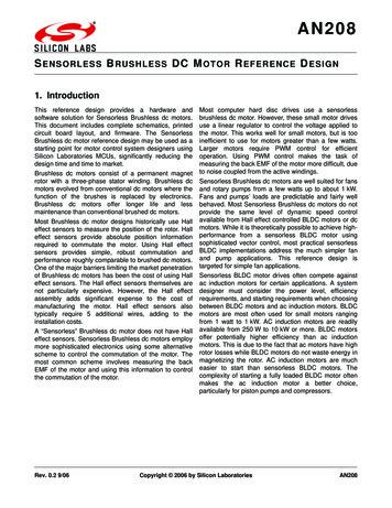
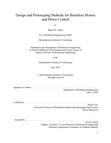
II. FIRST DESIGNThe first thing to decide was the machine type. Sinceaxial flux machine, Agni 95R, doesn’t fulfil the team needsregarding moment of inertia, the selection passes to a radialflux machine. The natural choice was a brushless permanentmagnet AC machine. It’s the preferred topology to electricvehicle traction, due to their inherent high efficiencies andexcellent power densities. Interior magnet machines has theadvantage of saliency which enables using reluctance torqueand protect magnets from flux pulsation in the air gap due topermeance harmonics. Between the several topologiesavailable, the selection fell in spoke rotor type. Thisgeometry hasn’t iron bridges and allows high air gap fluxdensity due to flux concentration principle.The results indicate that machine obtained is out ofweight limit even without including mechanical parts.Moreover the rotor diameter is close to Agni 95R whichmeans that moment of inertia is similar. Slot fill gross resultis too high for the standard overlapping winding consideredwith 24 slots. In conclusion this design doesn’t fulfil theteam goals. However this experience highlighted importanttopics to be considered in the future. This includes themodulation of slot geometry to avail the effects on coggingtorque; viability of analytical models imposed that must takeinto account the non-linearity of magnetic circuit; Epsteindata for BH iron curve; winding connection; skewmodulation; FEA methods non-dependent of mesh qualityto compute skewed and unskewed torque; iron lossescalculated by FEA and a transient solver to evaluate theeddy currents in the rotor.A. Cooling SystemIt’s possible to inset the machine desired in a certaincooling category, in terms of maximum TRV. Consideringhalf value of total ideal diameter to calculate rotor volumeand the maximum torque corresponding to 42.5 kW at 6000RPM, the calculation of TRV is defined by:Fig. 1 – Spoke rotor IPM machine [2]To initiate the first design, initial assumptions weremade, and then an optimization process was applied. Todefine poles number the first approach was choosing a goodfrequency to easily find low loss iron. Based on recentaerospace applications, it’s common to find 400 Hz in muchequipment. This defines 8 poles regarding the base speed of6000 RPM. A silicon oriented grain iron was employed aswell as the strongest NdFeB magnets.The optimization process taken was implemented bymeans of Fmincon Matlab routine. The objective functionwas the machine weight, which had to be minimized.Constrains were defined to guarantee the mechanical andmagnetic desired behaviours, expressed as function ofdesign variables. The nominal power and current density ofAgni 95R was tested to establish a comparison between twomotors.TABLE IOPTIMIZATION DESIGN RESULTSResultsValuesLength12 cmTotal diameter17 cmCurrent Density6 A/mm2Slot fill gross60 %Rotor Diameter10.2 cmLamination Weight10.4 kg Comparing with the following table is possible to havea rough estimative of cooling strategy to use.Fig. 2 – Typical values for TRV [3]Such results indicate that this machine needs anintensive liquid cooling strategy, for example using housingwater jackets. This feature is crucial in a permanent magnetmachine that uses NdFeB magnets. As they lose flux withtemperature rise, this has the effect of increasing cooperlosses to achieve the same torque level.III. PROTOTYPE MM03 V3: ELECTROMAGNETIC PROJECTTo fulfil team requirements it was necessary to changethe project paradigm. The natural solution was usingsoftware CAD tools, enabling a more detailed description ofmachine geometry. Moreover, software solutions turnpossible the iterative electromagnetic and thermal design byco-simulation, taking advantage of Windows Active X.Using this procedure is possible to integrate the coolingsystem into the electromagnetic project and get an accurateloss prediction by means of temperature update in a steady
state or transient analysis. For the electromagnetic designthe software used was PC-BDC from SPEED lab. For thethermal design the software used was Motor CAD fromMotor Design Ltd .A. Electromagnetic BasicsFirst design considerations were based on the analysisof following key equations [4]: {To maximize the alignment torque and achieve a highTRV it’s necessary to get a high EMF, in other words a highflux linkage at open circuit. To perform it, the ideal ismaximizing flux per pole by using strong magnets andavoiding the use of skew. However, since the machine hassmall radial dimensions due to the required diameter, it’sdifficult to attain such goal because it implies a large leastcommon multiple between slots and poles. Taking intoaccount the number of poles defined it means that requiresmany slots. As it s expected a heavily loaded machine inpeak power working point, was decided to use few slots toget wider teeth. The filtering effect of harmonic content inair gap flux density can be done by means of stator skew.Once a small air gap is used to increase the flux per pole,it’s expected that a high cogging torque result and skew cansolve the two problems at same time. This reduces the EMFand torque but it can be compensated by increasing thenumber of turns, and at same time guaranteeing the variablespeed drive required.The slots/pole combination selected was the Papstdesign. It is characterized by 12 slots and 8 poles, allowingthe use of wide teeth and performing a low slotting passingfrequency. This combination that became very popular inautomotive industry has good symmetry properties and nounbalanced magnetic pull is verified. It’s an expected resultbecause the greatest common divider between slots and poleis superior to 1 [6].B. MaterialsThe iron is the most important component in themagnet circuit. Since it’s expected high saturation in themachine and to explore strong magnets it’s advisable to useiron cobalt alloy. The product selected was VACODUR 49[5] suited to maximum power density machines and lowlosses, guaranteeing good mechanical properties.The strongest magnet available in the market is sinteredNdFeB, available in standard shapes. Sm-Co could also beconsidered but it’s heavier and with less coercivity field.For shaft, the criterion was searching for a stainlesssteel with the highest tensile strength possible, cheap andwith good machining properties. This was found withstainless steel 455.C. GeometrySome variables describing radial and axial cross sectionwere defined based on project constrains, like shaft radius,magnet inset, stator outer radius and cap thickness. Otherswere defined by means of several FEA to understand theimportant values to achieve in this design. Is the case ofrotor radius that was minimized to attain low moment ofinertia; air gap length and magnet width defined to achieve1.4 T of peak air gap flux density at open circuit; iron polearc to minimize pole-to-pole leakage and at same timemaximize the flux lines gathered by tooth arc; tooth width todeal with saturation at peak power; low slot opening tominimize the cogging torque as well as a higher slotopening angle and radial tooth tip length to avoid thesaturation in this areas. The axial stack length was definedin the maximum possible to achieve the ideal length of 20cm, increasing the flux per pole.D. WindingA balanced winding was developed to ensure equalresistances and inductances in all 3 phases. Papst design wasselected and to guarantee a double layer winding in 12 slots,the coil span defined was equal to 2. The non-overlappingwinding was not considered because it was difficult to find amanufacturer in Portugal to make such configuration.Considering a machine wound, the slot fill gross chosen was54%, in the limit for an overlapping winding.Fig. 3 – All phase’s layoutThe winding MMF shows that it is difficult to get asinusoidal distribution, which means that high harmoniccontent in MMF is expected.
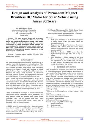
that dimensions defined for this variables fulfil the designgoals.Fig. 4 – 3 phases MMF and first electrical harmonicChecking the winding factors bar chart is possible tounderstand the filtering capability of this configuration.Fig. 7 – Air gap flux density: PC-BDC results Vs FEAIt’s clearly seen the slot opening modulation in the fluxdistribution. By adjusting the adequate calibration factors, ispossible to achieve good matching between the results.2) Tooth flux DensityOnce the phase EMF is calculated under the tooth fluxmethod, is important to achieve good agreement herebetween FEA and PC-BDC results.Fig. 5 – Unskewed winding factorsAs characteristic in Papst design, all winding factorshave the same value, which is 0.866. It’s low for firstharmonic and high for others. This suggests that isnecessary skew to filter the harmonic content in the air gapflux density and achieve a sinewound machine. It’simportant to attain such characteristic in the design becauseit makes it possible to use with more confidence the phasordiagram to analyse the machine, as well as controlprinciples based on FOC.E. FEA Open Circuit CalculationsThis kind of operation is a good way to give the firstanalytical model calibration, adjusting PC-BDC modelswith FEA results.Fig. 8 – Tooth flux density: PC-BDC results Vs FEAIn this waveform the slotting effect is not seen. Thegood agreement between both results is attained by meansof calibration factors. The most important is in the effectivetooth arc for flux collection at stator surface, to define thecorrect integration limits to apply Simpsons rule. In figure 6is seen that about 98% of tooth head collect flux lines.1) Air Gap Flux Density3) Phase EMFFig. 6 – FEA post-processor: open circuit calculationThe flux density values in rotor iron, tooth and statoryoke are good when an iron cobalt ally is used. This statesFig. 9 – Phase EMF: PC-BDC results Vs FEAPhase EMF is far from be sinusoidal which indicatesthe necessity of stator skew. The adequate adjustments bymeans of calibrations factors allow good agreement infundamental components.
4) Line-Line EMFFig. 10 – Line-line EMF: PC-BDC results Vs FEAThis line-line EMF is near from a flat top waveform,which may be bad for torque ripple. Its reduction isimportant to improve machine life time, however in thisapplication a safe tolerance could be given on the basis thatcar inertia filter much of this effects. It’s considered anacceptable value if less than 5% of peak torque is achieved.5) I-PSI Loop Unskewed7) I-PSI Loop SkewedFig. 13 – FEA I-PSI loop skewed: Phase EMF and 1st harmonicThis result states the skew effect in air gap flux densitydistribution. Phase EMF is practically sinusoidal andidentical to its fundamental component. Phasor diagram canbe used with accuracy to analyse the machine performance.F. FEA On Load CalculationsThe most critical working point is considered becausethis is the worst case operation scenario. The necessary peakphase current to achieve 42.5 kW at 6000 RPM is 267 Apk.1) I-PSI Loop SkewedFig. 11 – FEA I-PSI loop unskewed: FEA resultsThe diagram is not perfectly elliptical, which meansthat flux linkage has some harmonic content that has to befiltered, while the current is always sinusoidal as required.Fig. 14 – FEA post-processor: on load calculation6) Cogging TorqueAs expected, the machine is heavily saturated in thisworking point attaining peak values of 2.4 T in tooth tips.This is a little above of VACODUR 49 saturationpolarization, therefore no special concern is need on that.Fig. 12 – Cogging Torque: Unskewed Vs Skewed (skew 0.5)Special care was taken regarding the mesh density,rotor steps and convergence tolerance to get reliable results.The unskewed result based on co-energy calculation is 4.37N.m peak-to-peak. It’s a high value, typical when small airgap are used in conjugation with Papst design. When skewis equal to halt of slot pitch, the cogging is eliminated.Fig. 15 – FEA I-PSI loop skewed: PC-BDC Vs FEABlack result, which represents FEA calculation, is notperfectly elliptical. Saliency, permeance harmonics andmostly saturation distorts it. After calibration it was possibleto check the torque by means of following calculation:
2) Current, EMF and TorqueThe variable W represents the area under i-psi loop.The value obtained was 67.63 N.m, which indicates thatafter calibration the machine is developing the peak powerat rated speed, as it is required by the team.2) Transient SolverFig. 18 – Graphs: Current, EMF and torque Vs Rotor positionPhase EMF is close to sinusoidal waveshape howeversome torque ripple is observed.Fig. 16 – FEA post-processor: transient solver3) Air Gap Flux DensityThis result indicates a maximum eddy current density inthe magnet of 2.13 A/mm2 at peak power working point.This corresponds to a total magnet loss of 84.8 W. It’s ahigh value, mainly taking into account that NdFeB magnetslose flux with the temperature increase. To minimize sucheffect it’s considered that magnets are segmented incircumferential direction. The number of segmentsemployed was 16 due to manufacturing constrains.G. PC-BDC ResultsSince analytical models were calibrated with numerical,some preliminary results can be analysed for peak powerworking point at 6000 RPM.1) Phasor DiagramFig. 19 – Graphs: Air gap flux density unskewed Vs skewedThis graph gives good illustration about skew effect.Dark line represents the air gap flux density after skewingthe stator. The filtering effect obtained in conjugation withskewed winding factors, mainly those related to 5 th and 7thharmonic, turn possible to achieve the phase EMF depicted.4) Harmonic AnalysesFig. 17 – Phasor diagram: Blue-Voltage; Red-Current; Orange-FluxPhasor diagram is inside of voltage limit circle for a sixstep 180º operation.Maximum voltage available from inverter is enough todrive the machine until the base speed at peak power. Thesafe margin given between the circle limit and phase voltageis to guarantee the drive until 9000 RPM like required. Thiswas performed by connecting the winding in two parallelpaths, which has the effect of reducing machine reactance.Fig. 20 – Harmonics: Alignment torqueOnly the 6th harmonic is relevant and justifies thevariation observed in figure 18. The torque ripple attainedwas 4.4% of peak torque, which is within the limit defined.
5) Design Sheet ResultsTABLE IIMM03 V3 DESIGN RESULTSResultsValuesMotor Length21,2 cmTotal diameter11,6 cmCurrent Density28.9 A/mm2Peak Power42.5 kWCorner Speed6000 RPMLamination Weight7.72 kgInertia Moment8.56 E-4 kg.m2The main team goals are accomplished. The mostimportant variables, regarding the weight, diameter andinertia moment are achieved. In the last, the reduction whencomparing with Agni 95R is in the order of 1:28. The motorlength seems a little bit higher, however it takes intoaccount the end cap thickness which is not optimized.IV. PROTOTYPE MM03 V3: THERMAL PROJECTIn order to know the real machine performance isimportant to get the correct temperatures in all components.This depends on the cooling strategy used as well as thematerials chosen.A. MaterialsFor the housing and end caps a smooth material wasselected in order to minimize the contact resistancesbetween these two structures. A cheap material, compatiblewith anodized treatment is the aluminium. It has resistanceto corrosion and can employ water jacket directly in thehousing.Regarding the insulation and impregnation materials isnecessary to define the thermal class to be employed. It wasfound materials with thermal class H at good price. Themaximum hot spot of 180ºC it’s an acceptable starting point.The judgment has to be done in the thermal limitexploration of the machine, if it handles or not the peakpower during the time required. A class H polyester filmbased on PEN polymer was found. It has very low thicknesswhich improves the slot fill. The material chosen wasTeonex . For the impregnation the selection passes for apolyester resin, the typical material used, constrained to VPIapplication. This process guarantees perfect impregnationgoodness, with almost no air pockets. After researching,was found Dobeckan LE 6500. It’s an unsaturatedpolyester resin with 3 times the thermal conductivity ofcommon resins.For groundwall insulation was selected an aramid fibre,very tolerant to mechanical stresses and with goodabsorption properties for impregnation. This allowsreducing the interface gap between stator lamination andliner. The typical aromatic polyamide for this purpose isNomex .B. Cooling StrategyDue to high TRV identified in section II, an intensivecooling strategy is needed. Between the several strategiesavailable, the most simple and effective is housing waterjacket cooling. It’s standard in the manufacturing point ofview an guarantees a good dissipation of copper losses, asthey are the most significant. To achieve this it’s onlynecessary to reduce the interface gap between statorlamination and housing. This can be done by means of aheat paste sink.The most typical housing water jackets implementationis with axial duct or spiral ducts. As can be seen on table II,the machine perimeter is higher than motor length. Thismeans that for the same number of channels and geometry,the axial ducts have more area available than spiral ducts.This gives better balance in fluid flow, which allowsachieving the same temperature performance with lowervelocities and pressure drops. Therefore an axial waterjacket was implemented.The duct geometry may be circular or rectangular andsame considerations can be taken here too. Selecting azigzag housing water jacket by connecting all the channelsin series, it’s possible to attain the same area with lesschannels in rectangular form. Moreover, the extrusionprocess to be applied in the aluminium housing removesmore material in this case. This means that this feature leadsto a lightweight machine.1) Channel DimensionsTo select the optimum channel dimension a sensitivityanalysis was performed to understand the impact ofparameter change in thermal model by variation of a singleparameter. The parameter selected was the finpitch/thickness ratio (Fpt). Since the fin thickness is defined,increasing this variable allows increase channel width.Fig. 21 – Sensitivity Analysis: Ph Vs FptThe pressure drop in the housing, Ph, decreases withchannel width. When Fpt is superior to 10, variation is less
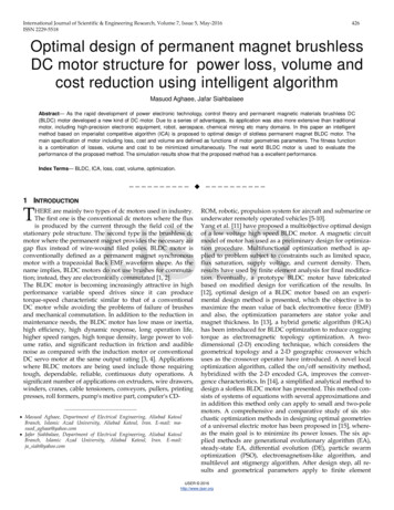
pronounced. It’s important to check if the same thinghappens with fluid velocity in the channel, Vf.Fig. 22 – Sensitivity Analysis: Vf Vs FptThe velocity in the channel decreases with area growth.It’s important to have high values of velocity to get a betterheat transfer coefficient, however it’s good practice inconstruction to keep values around 1 m/s. When Fpt issuperior to 10 the velocity decreases by steps, whichindicate that further increase don’t necessary represents agreat improvement in fluid flow. The temperature variationsin the critical components allow for final conclusions.The results on the graph consider an averagemanufacturing process, defining IG sh equal to 0.03 mm. Ifa perfect contact is considered, temperature reduction inwinding hot spot and magnet is 30ºC and 20ºC respectively.This justifies the great impact in the cooling and somemeasures to reduce this interface include the use of heatpaste sink. It typically reduces IG sh from 0.03 mm to 0.01mm, allowing a temperature reduction in winding hot spotand magnet of 18ºC and 14ºC respectively.V. RESULTSIn machine design is important to appraise machineperformance across the entire torque-speed envelope. Suchsolution was found with Motor LAB software from MotorDesign Ltd . This tool takes advantage of Windows ActiveX to connect PC-BDC and Motor CAD, performing thecalculation of torque-speed characteristics, loss andefficiency maps that can be used in an iterative designprocess.A. Saturation & Cross CouplingThe linear approximation used to describe flux linkagedoesn’t account for saturation and cross coupling effectswhich do not fit the purpose when modelling at highoperating currents. It’s considered that flux linkage isaccurately described by second order polynomial functionsas given [7].Speed Vs Shaft Output PowerFig. 23 – Sensitivity Analysis: Temperatures Vs Fpt70Ismax 267Ismax 20160Ismax 136Shaft Output Power (kW)Magnet temperature in red is not too sensitive to Fpt asthe average and hot spot winding temperatures. When Fptis equal to 11 the temperature attained is in the middle ofmaximum and minimum for each component. As this valueis in the range for the previous analysis, channel width canbe defined for Fpt equal to 11. This results in a zigzag waterjacket with 16 channels.Ismax 7050X: 6000Y: 42.4840302010C. Interface GapsA sensitivity analysis can be performed to checktemperature dependence to tolerances and manufacturingconstrains. This analysis will fall in the most importantcontact resistance for a housing water jacket cooling system:interface gap between housing and stator laminations(IG sh). This will determine the capability of the coolingsystem to extract the heat from the winding and iron.Fig. 24 – Sensitivity Analysis: Temperature Vs IG sh001000200030004000 5000 6000Speed RPM70008000900010000Fig. 25 – Saturation & Cross Coupling: Power Vs SpeedThis characteristic confirms that peak power is attainedlike required, independently of corner speed increase due tosaturation effect. The maximum power available, Pmax, is62.5 kW at 10000 RPM which is the machine limit. Thisdefines a power density of 6.3 kW/kg.B. Efficiency MapsThe proposed techniques also make it possible to plotthe efficiency characteristic over the full power-speedenvelope, performing an efficiency map. This is very usefulto understand where the ideal exploration regime of themachine designed is.
enough to support all the performances demands inautocross and endurance competition.Efficiency60965880928849300885 9084 982080388 92888039494270090949588938694Speed Vs Water Jacket Dissipation929595848187186 9959439185 90 9959388 8791 92 90 899394858849 94 9594868708880 83 8281 849289829008385 8486 8093 8487 81208388 8289 9180100 985909186 808287 810 88830200040006000Speed (RPM)80008210000802600Water Jacket Dissipation W28871 1886 9884988803 92729881188600993885Efficiency (%)4082Shaft Output Power (kW)50X: 8600Y: 2583250024002300220021002000Fig. 26 – Efficiency map: Power Vs Speed1900C. Limit EnvelopeThis study is directed to understand the machine limitsat steady state and transient operation. For steady state theprocedure was perform calculations with techniquesdeveloped considering that winding hot spot is fixed in thethermal class H limit, 180 ºC. Then the maximum powerspeed envelope is defined. For transient analysis the purposeis different. The main goal is to understand how much timemachine can handle the peak power at 6000 RPM. Previousstudies on Motor CAD show that it’s 80 seconds. Now theobjective is to confirm it.01000200030004000 5000 6000Speed RPM70008000900010000Fig. 28 – Steady state limit: Water jacket dissipation Vs SpeedThis graph illustrates the cooling system capacity. Thismachine has little area to dissipate the heat for such highpower densities involved. When the machine is operating at42 kW at 10000 RPM, housing water jackets are dissipating2.6 kW. This highlights cooling system performance forsuch a high TRV machine.2) Transient OperationSpeed Vs Shaft Torque7270X: 6000Y: 68.1168Shaft Torque (Nm)Contour plot shows a big area between 90 and 95% ofefficiency. Peak power at 6000 RPM is attainedapproximately with 91% of efficiency. In the autocrosscompetition the average power is 16 kW. Contour plotshows that it’s possible to attain such result with efficiencysuperior to 90% between 3000 RPM and 10000 RPM. It’s avery comfortable margin and gives good perspective for thefuel economy competition.666462601) Steady State580Speed Vs Shaft Output Power451000200030004000 5000 6000Speed RPM70008000900010000Fig. 29 – Transient operation: Torque Vs Speed40Shaft Output Power (kW)35X: 6000Y: 28.2530252015105001000200030004000 5000 6000Speed RPM70008000900010000Torque-speed characteristic indicates that the motordevelops 68.11 Nm at 6000 RPM continuously for 80seconds. This is very close from peak torque, whichconfirms the duty cycle results performed with Motor CAD.The machine guarantees a large margin of safety inexploration of peak power, mainly used in accelerationcompetition as it has to be concluded before 4 seconds. The80 seconds obtained are large enough to guarantee goodperformance and not excessive overheating.Fig. 27 – Steady state limit: Power Vs SpeedThe limit power achieved at 6000 RPM is 28.25 kW.This is an important result because the data obtained to thedifferent competitions with Matlab simulations indicatevalues below this. Therefore confirms that machine is goodD. Thermal MapsIt s also of interest to connect these analyses techniqueswith thermal modelling using Motor CAD software. Thisenables the generation of thermal maps, in a similar way tocreating efficiency maps.
Winding Max501604540120302510020Winding Max ( oC)Shaft Torque (Nm)140358015106050200040006000Speed (RPM)8000with heat paste sink. The water velocity and pressure dropsacross the housing have very good values, which mean thatthere is no problem with particles in coolant to wear awaythe aluminium surface. The intensive cooling strategy, themachine thermal class and VPI impregnation allows goodbehaviour in thermal limit envelop. The maximum powerdensity for this machine is 6.3 kW/kg.Improvements can be done to the future, namely:checking the skew effects and magnet losses with 3D FEAsoftware; study the influence of proximity losses in thedesign and explore a non-overlapping winding with adifferent combination of slots per pole.10000Fig. 30 – Winding hot spot thermal map: Torque Vs SpeedREFERENCESThis thermal map shows that the winding hot spottemperature increase with machine loa
II. FIRST DESIGN The first thing to decide was the machine type. Since axial flux machine, Agni 95R, doesn’t fulfil the team needs regarding moment of inertia, the selection passes to a radial flux machine. The natural choice was a brushless permanent magnet