Transcription
Journal of Artificial Intelligence in Electrical Engineering, Vol. 6, No. 23, November 2017Design and optimization of dc brushless permanent magnet motorHassan hatamlu, Zahra hatamlu, ramin borjali navesiDepartment of Electrical Engineering, university college of science and technology(Elm ofann),urmia,iranEmail:hhatamlu@gmail.com, zhatamlu@yahoo.com, r.borjali.68@gmail.comAbstractElectric motors with lots of applications in various sectors of industry have unique features such ashigh reliability, high efficiency, quick acceleration, and are found in very small sizes. Brushless DCmotors meet these requirements well. In this study, the design of a brushless DC motor speed limits forthe particular application at 1800 rpm was provided that can be equivalent to 140 watts output. Thepresent study intends to increase the power density, efficiency and to reduce engine weight by using thefinite element method. According to the analysis of the existing motors and parameter extraction, theywere compared using software for high electromagnetic torque and low weight. In this article, we havefocused on the permanent magnet by testing different types of magnets and comparing the results offinite element analysis. The existing magnets were made of ceramics with the lowest density, but thepermanent magnet in software method has the highest energy density.Keywords: brushless DC motors, optimization, finite element method, new structure.rest or comply with international standardsand comply with the requirements of therequesting electric motor. In this study, thedesign of a brushless DC motor speed limitsfor the particular application at 1800 rpmequivalent to 140 W output was provided.At first, the numerical model and governingthe design of this engine have been studiedand then according to the equations,flowcharts for engine design have beenpresented. External rotor motors of the typehave been put on magnets using the rotorsurface and the engine type is called SMPM.1. IntroductionDue to the needs of society, and to reducethe price of permanent magnets, consumersseek to replace permanent magnet motorswith other engine types. Weight, size,efficiency and reliability are importantfactors in the selection of electric motorsrequired in industry. The power output ofthe engine and its speed is directlyproportional to the volume of magneticmaterials for cars. Thus, increasing enginespeed and its dimensions will lead to weightloss. The design for electric motors usuallyinvolves two main steps:1- Themaindimensionsandparameters for calculation engine2- Predicting engine performance2. Motor DesignIn this section, we explain the geometry,magnetic and electrical requirements anddiscuss about the engine design. Accordingto Figure 1, we can determine geometricparameters.In an electric charge and with certainmagnetic specific rotor diameter, thediameter of the end machine could beIn the first phase, the engine dimensionssuch as length and outer diameter of thestator core must be selected. A number ofquantities related to engine performancesuch as torque and power output should also1
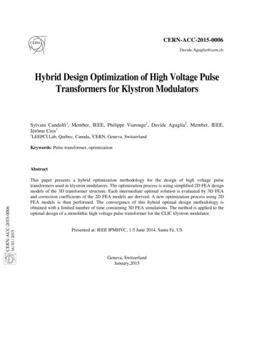
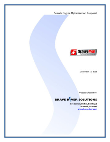
H. Hatamlu , Z.Hatamlu ,R.Borjali.Navesi : Design and optimization of dc brushless permanent increased and the number of poles could bereduced.2-2. specific motor design analysis:In this section a direct current brushlesspermanent magnet motor with intermittentfunction 24 V, 140 W of output powerallowed 180 W maximum power and 1,800rpm examined:There are a number of limitationsdiscussed in engine design:Fig.1.Topology of radial flux motors withgeometryw ry w sy 2. .B g .R si1) Flux density in the air gap: Theamount of flux in the air gap is usuallybetween 4.0 to 7.0 Tesla, respectively.In this design we selected an amountequal to 58/0 Tesla to carry theinvestigation.(1)4. p .B pRelations Is the radius of the following:R sb R so w biR si R sb d s R ro L g(2)2) Air gap width of 1 mm is assumedinitially.3) Bow step towards the polesR ri R ro L m w ryPole and pole angular dimensions can becalculated according to the followingformula linked together:2 p , p R si p(3)NmSteps in the inner radius of the rotor coil canbe obtained through the following equation:(4) c cp p4) As mentioned above, 3-phase motors,12 slots, and 8 poles have beenselected.5) No-load speed is four percent more fullload speed than the 4/10 radians perseconAssuming that all magnetic flux linesgenerated by the magnet, with the exceptionof flux, we pass through the gap:(5)B A K B A2-1. Choose a rotor topology:In the outer tour is selected designed towork with permanent magnets at highspeeds. To prevent magnets from detachingfrom the rotor by centrifugal forces, therotor surface is enclosed in a thin metallayer and if the outer rotor needs this metalcylinder, six different permanent topologyrotors magnets are shownmm1ggThe number of armature conductors iscalculated as follows elderly:Z 3T3 64.2 6300DLBg kw Ia 0.052 0.009 0.58 1.9 5.9The slot pitch and density per rack is: D 52 s 13.61 (mm)Ns 12Btr Fig. 2. Topology of permanent magnet rotors2Bav D 0.945 52 1.83 (T )wtrS7 12
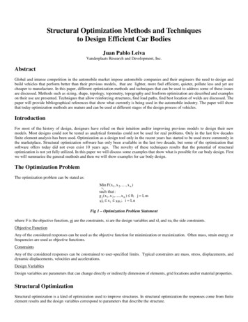
Journal of Artificial Intelligence in Electrical Engineering, Vol. 6, No. 23, November 2017Table 1.Values View MagnetThemaximumenergyAngle ofdeviationPermittivityBackStepNumber258253kJ / m3Degmm1.1DensityCurietemperature4.7 5.7310 gr / cm3 C2-3. re1180 %/ CGrade Cdiameter) are identified. The stator slot inaccordance with Figure 3 and Table 3shows the parameters given to theapplication.Stator reactance resistance is fixed againstthe 0.3 Ohms at 25 degrees, respectively. Asa result, we have:pcu R .I 2 0.3 (5.9)2 10.44 (Watt )Weight teeth of the armature and the corecan be calculated as follows: Gc [D2 (Di 2ds )2]lia 4 [(0.25)2 (0.052 2 0.0554)2] 0.95 0.009 7750 0.21(kg4Fig.3.The stator slot designAccording to the proposed numericalrelationships, an optimization method toobtain unknown parameters can be defined.The purpose of optimization method is tohelp the engine to get the lowest possibleweight. Selection goal in this researchenabled Motors weight that should be in theleast possible amount. The copper lossesand weight constraints are limited bymagnets. It should be noted that for themechanical strength, no magnetic saturationand calculating efficiency is also taken intoconsideration regarding the constraintsrequired.And, efficiency is equal to: pa140 100% 100% 91.68%pa pcu pcore ps140 10.44 0.86 1.43.Motor design using the softwareSoftware RMxprt, software for the designand analysis of electric machines wasprovided by ansoft. Input featuring the mainelectrical parameters (power, frequency,and voltage) and the geometric dimensionsof the machine (external and internaldiameter of the stator, the rotor and thestator core and the rotor outer and inner3N35
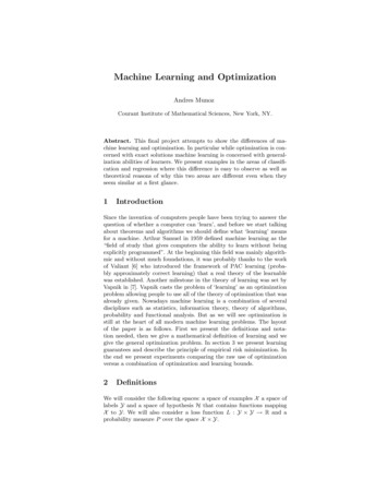
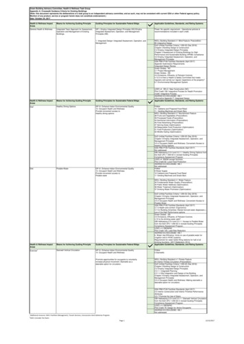
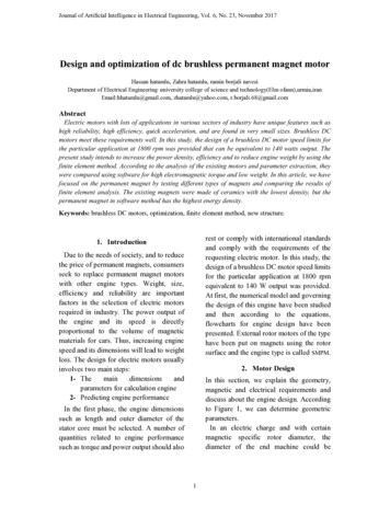
H. Hatamlu , Z.Hatamlu ,R.Borjali.Navesi : Design and optimization of dc brushless permanent Coil design shown in Figure (4) withsingle-layer winding three-phase windingstogether with step 3 represents almost allcars brushless permanent magnet.100.0080.00(% )60.0040.00Curve InfoEfficiency20.000.000.00500.001000.00n (rpm)1500.002000.002250.00Fig.6.Designed motor efficiency4. Finite Element AnalysisHere no-load analysis is done on motorand it is assumed that the rotor is stationary(static magnetic analysis). After the fluid isinjected into the stator windings and targetonly modeling engine is in no-load mode,figure 7 shows the motor flux lines (due tothe symmetry of a fourth cut). The magneticflux lines were highest and it passes afterpassing through the air gap. The stator teethand stator yoke their way through thesurrounding magnets and rotor closes.Figure 8 shows a two-dimensional view ofa simulated motor show.Fig.4.The coil provided with ApplicationsFigure 5 shows, the waveform of themagnetic flux density gap shown in terms ofelectrical angle. Curved trapezoidal formand the range is 58.8. Engine efficiency isalso in the form (6).0.60Curve InfoAir-Gap Flux Density0.40( T e s la )0.200.00-0.20-0.40-0.600.00125.00Electric Degree250.00375.00Fig.5.The air gap flux densityFig.7.Motor no-load flux lines4
Journal of Artificial Intelligence in Electrical Engineering, Vol. 6, No. 23, November 2017Table 2.Motor design parametersAnalyticalSolutionunitparameter3-Number of phases8-Number of poles12-Number of tracks170WattMaximum power output140WattAllowed output power0.64NmMoment of inertia24VTerminal voltage1mmAir gap1800RPMspeed23.3%-Track occupancy rate0.58TFlux density in the airgap9mmThe inner diameter ofthe stator52mmThe outer diameter ofthe stator9.4mmThe thickness of a router127mm2The area of copper perslot0.412mmWire diameter6mmThe height of the groove9mmDuring the motorarmature0.00693Kg.m2Mass inertia of the rotor10.44wattCopper losses0.86wattCore loss91.68%----EfficiencyTable 3.Parameters to the applicationamountparameter amountAutomotive Operation5Parameter4Number tage1800SpeedNd Fe BType ofmagnets56The outerdiameterof thestator9Duringthe roto0.95M19-24GIron rotorM1926GStator iron0.5Embrace12Thenumber f themagnets6300Thenumber ofarmatureconductorsBe fixedType ofbarbrushlessType ofcarStackingfactor
H. Hatamlu , Z.Hatamlu ,R.Borjali.Navesi : Design and optimization of dc brushless permanent 5. ConclusionReferenceAccording to the simulation results andmany articles in the field of three-phasebrushless direct current motors it is wellknownthatmulti-phasebrushlesspermanent magnet direct current motor hasa much better performance characteristicsthan conventional three-phase motors.Torque and speed of the commutationphases have fallen sharply. The engine is agood choice for military applications.Using standard electromagnetic fieldanalysis, a brushless permanent magnetmotor was designed for high-speedapplications sample design enginesatisfactory results in practice showed thatthe results obtained are as follows:1. In Speed of 1800 rpm the engine isdesigned for this value, the amount ofengine power and efficiency by solvinganalysis and simulation was a goodmatch.2. According to analytical results andproviding weight-optimized softwareengine at high speeds suitable for usersin the table 4 has come; engine weight isreduced compared to existing engines.3. Probably due to the high efficiency ofbrushless and brush motors we observeda loss about 78% to 98%. The design andcalculation efficiency was about 91%and the design software value increasedto more than 91%. The accuracy of theresults was obtained4. By testing with different types of magnetsand comparing the results of finiteelement analysis. The existing magnetsmade of ceramics with the lowestdensity, but the permanent magnet insoftware method has the highest energydensity.[1] P. Pillay and R. Krishnan, Optimized Designof a Brushless DC Permanent Magnet Motorfor Propulsion of an Ultra-Light Aircraft ،Original scientific paper[2] David G. Dorrell, Design Requirements forBrushless Permanent Magnet Generators forUse in Small Renewable Energy Systems,Member IEEE[3] K. A Corzine, S. D. Sudhoff, “A HybridObserver for High Performance Brushless DCMotor Drives,” IEEE Transactions on EnergyConversion, Vol. 11, No. 2, pp 318-323, June1996[4] A.Shirazdi, design and analysis of a highspeed brushless direct current motor for use inthe aerospace industry, Malek AshtarUniversity, nineteenth Iranian Conference onElectrical Engineering (2011).[5] M.Azadi, Modeling and simulation 9-phasebrushless DC motor, Shahrood University ofTechnology Faculty of Electrical Engineeringand Robotics, Twenty-fifth InternationalConference on Electricity (2010).[6] S. Morimoto, Y. Tong, Y. Takeda, T. Hirasa;“Loss minimization control of permanentmagnet synchronous motor drives”, IndustrialElectronics, IEEE Transactions on, vol. 41,pp. 511-517, 1994[7] Haifeng Lu, Lei Zhang and Wenlong Qu “Anew torque control method for torque rippleminimization of bldc motor with unideal backEMF” IEEE Trans on Power Electronics, vol.23, No.2, March 2008[8] J.R. Hendershot, T.J.E. Miller,Design ofBrushless Permanent-Magnet Machines.Motor Design Books LLC: Second Edition,2010.[9] A.Kolah dooz, design and thermal analysis abrushless permanent magnet motor,production Iran of the Tenth Conference(2009).6
Fig. 2. Topology of permanent magnet rotors 2-2. specific motor design analysis: In this section a direct current brushless permanent magnet motor with intermittent function 24 V, 140 W of output power allowed 180 W maximum power and 1,800 rpm examined: There are a number of limitations discussed in engine design: 1) Flux density in the air gap .Author: Hassan hatamlu, Zahra hatamlu, ramin borjali navesiPublish Year: 2017