Transcription
Journal of Engineering Science and TechnologyVol. 11, No. 8 (2016) 1135 - 1154 School of Engineering, Taylor’s UniversityDESIGN OF FILL AND FINISH FACILITY FORACTIVE PHARMACEUTICAL INGREDIENTS (API)NUUR LAILA KHAIRUDDIN, NORLIZA ABD. RAHMAN*,NUR SYAFIQAH KAMARUDINDepartment of Chemical and Proses Engineering, Faculty of Engineering and BuiltEnvironment, Universiti Kebangsaan Malaysia, 43600 Bangi, Selangor, Malaysia*Corresponding Author: norlizajkkp@ukm.edu.myAbstractFill and finish operations continue to be one of the most heavily outsourcedactivities in the biopharmaceutical manufacturing market today. There are a fewaspects that need to be consider in outsource activities like logistic, storagecondition, facility certification and audit as regulations and standards which themanufacturer should adhere. Risk would be greater and extra care should betaken when outsource from foreign fill and finish facility. Thus, the internalaseptic fill and finish facility with audit checklist will help to minimize the riskduring logistic and storage and also minimize the cost for outsource fill andfinish facility. The data collections are through survey and conceptual designwith simulation as the execution part.Keywords: Active pharmaceutical ingredients, Aseptic, Design, Facility.1. IntroductionAccording to World Health Organization (WHO), Active PharmaceuticalIngredients (API) is any substance or mixture of substances intended to be used inthe manufacture of a pharmaceutical dosage form and that, when used so,becomes an active ingredient of that pharmaceutical dosage form. The substancesare intended to furnish pharmacological activity or other direct effect in thediagnosis, cure, mitigation, treatment or prevention of disease or to affect thestructure and function of the body [1]. There are two classifications of API whichare inorganic substances or organic substances that isolated from materials ofanimal or human origin and synthetic or semi-synthetic or isolated from herbalsources or microorganisms.1135
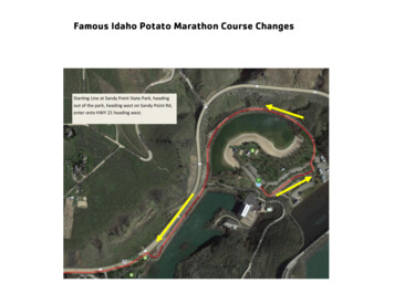
1136N. L. Khairuddin et HNPCBPALPIC/SQAQCROISPAHU SPAHWFIWHOAir Handling UnitActive Pharmaceutical IngredientsCurrent Good Manufacturing ProductEuropean Medicines AgencyErythropoietinFood and Drug AdministrationGood Manufacturing PracticeHigh Efficiency Particulate AirInternational Conference on HarmonizationMaterial AirlockMinistry of HealthNational Pharmaceutical Control BureauPersonnel AirlockPharmaceutical Inspection Co-operation Scheme (PIC/S)Quality AssuranceQuality ControlReturn On InvestmentSatellite Process Assurance Hub (SPAH)U Satellite Process Assurance HubWater for InjectionWorld Health OrganizationFor Malaysia, the regulatory pathway and mandatory control of API product isgoverned by the Ministry of Health (MOH) through the National PharmaceuticalControl Bureau (NPCB) division. The NPCB will reduce the risk of sourcingsubstandard or contaminated materials. Hence, secure a constant sourcing ofactive ingredient of appropriate quality which will safeguard the public. Generallyfor pharmaceutical manufacturing, the activities will be involved are research,development, manufacturing and finally marketing as shown in Fig. 1. In themanufacturing process, it will cover the inbound logistic, bulk active, bulkformulation, filling, packaging and outbound logistic. Based on the flow, it showsan aseptic filling of biologics drugs is one of the most crucial processes inbiopharmaceutical manufacturing because it is a highly technique drivenprocesses and have the potential safety impact to the compromised patient.Aseptic filling is an aseptic process that requires close coordination and complexinteraction between personnel, sterilized product, fill and finish equipment orsystem, cleanroom environment and support facilities, as well as the sterilizedfilling components [2].When outsource for external fill and finish facility, there are few aspect thatneed to be consider like logistic, storage condition, facility certification and auditas well as regulations and standards which the manufacturer should adhere. Riskwould be greater and extra care should be taken when outsource from foreign filland finish facility. Integrated bulk manufacturing and fill and finish plant offerhuge advantages for the biopharmaceutical products because it deals with thefinished product in its most valuable state where the risks of a contaminationevent or other failure area at their highest. Internal aseptic fill and finish facilitywill help to minimize risk during logistic and storage, minimize the cost forJournal of Engineering Science and TechnologyAugust 2016, Vol. 11(8)
Design of Fill and Finish Facility For Active Pharmaceutical Ingredients (API)1137outsource fill and finish facility and thus aid to shorten time for drug registrationinto market for commercialization.Fig. 1. Overall flow for biopharmaceutical manufacturing.2. MethodsThe data is collected and divided into two sections which are data collectionthrough survey and conceptual design with simulation as the execution part. Bothphases are detailed out in Table 1.Table 1. Outline of project methods and expected cts tobe inspectby auditor.-Providechecklistfor plantaudit2Feasibilitystudy-Marketand salesprojection-DetermineplantcapacityResearch LayoutExecution345DevelopPerformProcessflow sheet simulation economicsrepresentusing-Determinethe overall SuperProthe capitalprocessDesignercost-Materials,for fill and tioncostandestimationparametersandare e forplantconstructionandcommissioning2.1. SurveyTo conduct the survey, two data collections are required to establish auditchecklist and determination of plant capacity.Journal of Engineering Science and TechnologyAugust 2016, Vol. 11(8)
1138N. L. Khairuddin et al.To establish the audit checklist, a literature research about Malaysianguidelines for aseptic pharmaceutical facility is conducted by evaluating thepremise requirements provided by the Ministry of Health (MOH) through theNational Pharmaceutical Control Bureau (NPCB) division. Based on this, thecurrent flow and highlight aspect is list out in a checklist format making themanufacturer easier to plan the intended facility layout thus meet the standardcriteria. The audit checklist will also cover on overall good manufacturingpractice according to Pharmaceutical Inspection Convention, PharmaceuticalInspection Co-operation Scheme (PIC/S) and International Conference onHarmonization of Technical Requirement for Registration of Pharmaceuticals forHuman Use (ICH). Both guidelines are similar as per European MedicinesAgency (EMA) guidelines.To determine the aseptic fill and finish facility, feasibility study will beconducted to evaluate the market and sales projection of the intended product.Data from the demand and supply of Erythropoietin (EPO) in Malaysia is studybased on required injection needed per patient and vial volume. By calculation,estimation of potential quantity of vial production is decide whether with existingmanufacturing plant capacity is tolerable or not. Through this, the equipment andmachine needed for the dedicated process will be determined.2.2. ExecutionThere are two parts to evaluate the execution section. First is to develop the flowsheet which represent the overall aseptic fill and finish process including thedefine materials, product and personnel flow to ensure no risk of crosscontamination. Process for aseptic fill and finish will cover three different lineswhich are vial filling line, lyophilization or powder line and prefilled syringe line.Decision will make based on the guideline provided by PIC/S and the example ofthe established fill and finish facility plant. The conceptual layout design of thefacility will also relate to the process flow sequence for dedicated line.The conceptual design for aseptic fill and finish facility is define by knowingthe capacity of the plant, process and equipment to layout in the process. Afterthat, simulation will be conducted by using Super Pro Designer (Lite Ed.)software version 8.5, Build 3 by Intelligent Inc. By adding the process steps (unitprocedure), the process batch modeling are executed.Apart from that, cost analysis and economic evaluation will be obtain throughSuper Pro Designer where the operating cost estimation cover the raw materials,labor, utilities etc. Profitability Analysis will be performed by calculating thegross margin, return on investment and payback time of the proposed asepticprocess based on the following formula.Gross Margin Gross ProfitRevenues(1)Return on Investment (ROI) Payback time (in years) Net profitTotal investmentx 100%Total investmentNet profitJournal of Engineering Science and Technology(2)(3)August 2016, Vol. 11(8)
Design of Fill and Finish Facility For Active Pharmaceutical Ingredients (API)1139The project timeline for construction and commissioning of the aseptic fill andfinish also will be projected. Based on the Return On Investment (ROI) andpayback time obtain, comparison between building an integrated fill in finishfacility with the existing manufacturing facility or outsourcing for external filland finish facility will be made. The decision will be based on the current EPOprocess for commercialization stage.3. Results and Discussion3.1. General requirementPharmaceutical Inspection Convention, Pharmaceutical Inspection Co-operationScheme (PIC/S) and International Conference on Harmonization of TechnicalRequirement for Registration of Pharmaceuticals for Human Use (ICH) had setout a standard and guideline for premise and APIs which equivalent to EUGood Manufacturing Practice guide [3]. Before plant commissioning, the layoutplan must be submitted to the Centre for Compliance and Licensing of NPCBfor evaluation.According to De Carlo et al. [4], the main key facility layout problems aretransportation where the cost could be reduced by 10% to 30% annually withefficient facility planning. Effective facility layout also helps to decrease work inprocess and throughput times where it can simply facilitate the control ofinformation and material flows. Meanwhile, Lamba [5] suggest that preferredlayout for a pharmaceutical facilities are segregation between raw materials andfinal products involving different classes, perform closed operations wherepossible, ensure orderly flow direction, provide distinct staging areas if requiredbetween process steps, cleanable production suites and equipment with suitableenvironments for controlled areas for storage and process.In term of external and internal environmental protection, environmentalparameters such as temperature, humidity, cross-contamination control must beaddressed in facilities dedicated to the manufacture and packaging of APIs [6].The link between the premises’ interior and exterior should be through airlockswhich are Personnel Airlock (PAL) and Material Airlock (MAL) change rooms,pass boxes, pass through hatches, etc. These entry and exit doors, for materialsand personnel, should have an interlock mechanism or other appropriate system toprevent the opening of more than one door at a time [7]. Basically, the facilityusually will consist of Current Good Manufacturing Product (cGMP)Manufacturing area, Utilities area, Quality Control (QC) laboratories, warehouseas well as administrative offices.3.2. Design requirementAccording to PIC/S Guideline as well as United States (US) Food and DrugAdministration (FDA) and EMA Guideline, to maintain cleanliness, themanufacturing staff is required to enter the controlled environment of the processareas through a plant locker and wash up space. Personnel are required to changeinto appropriate garments. Then, they pass through an airlock to access controlledclean areas such as the preparation area and filing area.Journal of Engineering Science and TechnologyAugust 2016, Vol. 11(8)
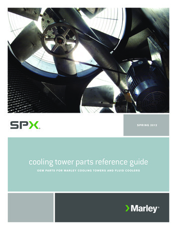
1140N. L. Khairuddin et al.To assure proper flow of equipment and materials, soiled equipment isremoved from each suite through an air lock, and is staged in a soiled equipmentarea before cleaning. Cleaning is done in an equipment washing or glasswarewashing area, outside the staging area. After being washed, the equipment isstored in a designated clean storage area. Before use, the equipment is sterilized inthe autoclave or a depyrogenation oven. After that, leaves the clean equipmentarea and goes into the production area through air locks.Once released by QC, the raw materials from the warehouse will enter theproduction area through air locks into the dry storage area. Nonchemical materialsmay enter through personnel entrance. Materials are held in dry storage atambient temperature, or in a cold box until needed in the weighing room. Aftervarious components are weighed, the buffers or diluents are prepared in thepreparation area. The solutions are then filtered, sterilized, and transferred to nextfilling process. Solutions can be transferred by aseptic containers, but usuallypressure are transferred through piping. Final formulation or finishing operationscan be accomplished in many ways, from hand filing operations to semiautomated equipment. Final finishing operations are always conducted underaseptic conditions.Because the area is clean, particulate-generating or dirty items (such aspackaging) should be removed before materials are brought into the formulationor finishing areas. Cardboard boxes containing materials are brought to be filledare moved from the warehouse into the material staging area to be unpacked.All exterior cardboard materials are removed and the plastic-wrapped materialis moved next to the washing or sterilization equipment. Shrink wrap andinternal cardboard separators are removed at the in the feed tray of the washeror autoclave. Components such as fill heads or tubing that required in the fillingsuite, are cleaned and sterilized in a double-door autoclave. The second dooropens into the cleanroom. Formulation tanks are outside the sterile filling room,in adjacent room. A single fill line passes from the bulk tank into the fillingarea, where a sterile connection is made with the filling equipment. A localsterile class 100 environment is maintained continuously above the filling andcapping operation [3].If lyophilization is required, filled vials are loaded and a vacuum is pulledwithin the chamber to remove all moisture from the product. The amount oftime required for this operation depends on the amount of moisture to beremoved. The materials are then capped and collected into tote bins, placed incage, and transported to a cold storage box for holding until released by QC.Once released, they are moved into the packaging area for inspection, labellingand final package assembly.A major design concern for the manufacturing areas is to assure optimalpersonnel flow patterns and material movement. This is important for efficientoperations and for Good Manufacturing Practice (GMP) compliance. GMPrequires that separate well-defined areas to be provided for different stages of themanufacturing process. GMPs also require the manufacturing area and each spacecontained therein, be designed to allow for the orderly arrangement of processingequipment to prevent product contamination or mix-up [8]. Figures 2 and 3 showsexample of layout proposes by [6, 9].Journal of Engineering Science and TechnologyAugust 2016, Vol. 11(8)
Design of Fill and Finish Facility For Active Pharmaceutical Ingredients (API)1141Fig. 2. Example of filling area layout [9].Fig. 3. Example layout plan for cytotoxic drugreconstitution preparation facilities [6].3.3. Cleanroom classificationCleanrooms are divided into different classes in standards. The equivalence ofclasses form different international standards is shown in Table 2. For themanufacturing sterile products, there is certain classification either grade A, B, Cor D as per Table 3.Based on the classifications of the room, there are limits outline by MOHwhich are particle count limit, microbial limit, temperature, humidity and airpressure differential limit to control the internal and external environmental in thecleanroom. Details of the specification are described in Tables 4, 5 and 6.Journal of Engineering Science and TechnologyAugust 2016, Vol. 11(8)
1142N. L. Khairuddin et al.Table 2. Classification of clean areas [2].ISO/TC(209)14644ISO 5WHOGMPUS209EFDAcategoriesGrade AM 3.5Class 100Grade BM 3.5Class 1000ISO 5Grade CM 5.5Class 10000ISO 7Grade DM 6.5Class 100000ISO 8EU annex 1:4 categories (A-D)Grade A(Critical 100)Grade B(Aseptic 100, nonunidirectional)Grade C(Controlled 10 000)Grade D(100 000)Table 3. Terminally sterilized products [10].GradeACDExample of operationFilling of product, e.g.: aseptic preparation and fillingPreparation of solutions e.g.: preparation of solution to be filteredPreparation of solutions and components for subsequent filling, e.g.:handling of components after washingTable 4. Particle count limit for cleanroom [6].GradeABCDAt RestIn OperationMaximum permitted number of particles/m3 equal to orabove 0.5 µm 0.5 µm 0.5 µm 0.5 µm3,520203,520 20203,520 5Table 5. Recommended limits for microbialcontamination in the operation state [6].GradeABCDRecommended limits for microbial contaminationSettle platesContactplatesGlove printAir sample(diam,90(diam,55 mm)5 fingers3cfu/mmm)cfu/platecfu/glovecfu/4 hours 1 1 1 110555100502520010050-Journal of Engineering Science and TechnologyAugust 2016, Vol. 11(8)
Design of Fill and Finish Facility For Active Pharmaceutical Ingredients (API)1143Table 6. Temperature, humidity and air pressure differential limit [6].RoomPreparationComp. PreparationGowningChangingTemperature(⁰C)RH (%)Adjacentroom20 220 220 220 255 555 555 555 e(Pa) (10-15) (10-15) (10-15) (10-15)According to Kitain [10], in order to reach the B, C, and D air grades, thenumber of air changes should be related to the size of the room and the equipmentand personnel present in the room. The air system should be provided withappropriate filters such as High Efficiency Particulate Air (HEPA) for grades A,B, and C. For class D in operation, where the permitted particles number is notspecifically define, just an appropriate alert and action limits should be set for theresults of particulate and microbiological monitoring. If these limits are exceeded,operating procedures should prescribe corrective action.3.4. Filling process flowProcess flow must be separated from all other flows of people, raw materials,supplies and utilities. The greater the separation, the more likely the product purityand quality is maintained. The process and personnel flows within the productionsuite should allow for easy removal of rejected product without need to leave thesuite or require other personnel to enter the suite simply to remove the rejectedproduct. A separate passage, accessible form the suite should be considered.A similar concept can be used for product passing from one production suiteto another for next process. The use of product passage will allow productioncleanliness in both suites to be maintained. Personnel can pass completed productto the passage, sample be evaluated and remove if rejected. Once the productionis completed, product needs to be held in a quarantine area until QC evaluationand release.The product flow should progress from the receiving of the materials throughthe production process, and finally shipping area. The path should be linear,continuous in one direction without backtracking to assure that contaminationdoes not occur by mixing up released and rejected materials.3.5. Personnel flowPersonnel flow is unlikely to parallel product flow. Product flow is located in theproduction area with prescribed path. Personnel flow occurs throughout thefacility, with differing intensities and paths. People cross the boundaries ofdifferent areas, from production to administration, warehouse and lab. The mostcommon paths of travel must be identified based upon the strongest adjacencyand daily communication. The critical paths must be given top priority tominimize both travel time and interference with other operations. The number,frequency and distance personnel trips must be considered as the priorities areJournal of Engineering Science and TechnologyAugust 2016, Vol. 11(8)
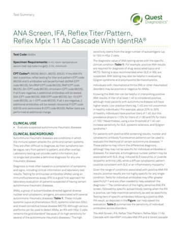
1144N. L. Khairuddin et al.established. As part of aseptic control, gowning rooms play a critical role in thefacility layout since operator needs to wear dedicated cleanroom clothing whichdesign to limit the rate of particle generation from the person. Usually two grades(levels) of changing rooms required: low for changing from normal clothing(street clothes) to factory (clean) clothing and high for changing from cleanclothing to full coverage suit [9].3.6. Product flowThe primary concern of a biotechnology is the integrity of the product start fromthe material delivery to final manufactured product shipment. Well defined flowpaths enhance the ability to maintain the product integrity, reduces potential ofcontamination and mix-up of materials and products. Raw materials classified inseveral distinct categories quarantine, approved and rejected within the facility atthe same time based on QC testing. The flow of raw materials and productsthrough the facility should follow the production process. The flow should bearranged to eliminate backtracking and crossing paths, thus avoiding point ofcontamination. As quarantined as a rejected material without crossing theproduction material flow pattern.Cunnigham [11] propose example design in Genentech’s fill finish facility inHillsboro, Oregon as per Fig. 4 where the design considering manufacturingprocess moves materials, equipment and personnel in a simple uni-directionalflow, reducing the chance for cross-contamination. The product and materialsentering through warehouse, moving 3 level manufacturing building and thenstored in the distribution center prior to be distributed. Fill suites and inspectionareas were positioned adjacent to each other with view windows to facilitate easycommunication and monitoring the process.Fig. 4. Uni-directional flow of product and materials [11].Journal of Engineering Science and TechnologyAugust 2016, Vol. 11(8)
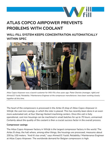
Design of Fill and Finish Facility For Active Pharmaceutical Ingredients (API)11453.7. Material flowAs part of GMP requirements, raw materials must be kept separate from inprocess materials and finished product to avoid mix up. Thus, raw materialsshould be received in an area separated from finished product shipping. Materialflows considered the raw materials, finished goods, waste, product (in-process,intermediate and final) as well as equipment that either clean, dirty as well ascontainers [9] as illustrated in Fig. 5. The raw materials must be held separatelyuntil QC samples and verifies then. Once released for production, materialsshould be separated from rejected materials. The rejected materials must be keptseparate from all other materials to eliminate the possibility of contamination ofto release materials. Once raw materials are released for production, they areplaced in the process circulation flow.The layout of facility should consider the process flow, material flow andpersonnel flow to minimize risk of contamination or cross contamination have clearmaterial and personnel flows (unidirectional whenever possible) with unambiguousdefinition of the GMP zones thus separate clean and dirty items [5]. As suggest byManfredi [9], Fig. 6 shows the desired and less desired layout plan for a facility.3.8. The combinations of all flow directionFigure 7 shows the overall aseptic fill and finish process flow for three differentlines of final product type to be manufacturer which are vial, lyophilization andpre-filled syringe. Each process step required different cleanroom classificationfor operation depends on the criticality and guideline requirement [10]. To assiston plant layout, the process step area is differentiate by color: gray for Grade A,red for Grade C and green for nonclassified.Fig. 5. Example of material and personnel flow [9].Journal of Engineering Science and TechnologyAugust 2016, Vol. 11(8)
1146N. L. Khairuddin et al.(a)(b)Fig. 6. Facility layout option after considering process, material andpersonnel flow: (a) Desirable layout (b) Less desirable layout.The new aseptic fill and finish facility will be in two level modular plantcomprises of receiving area, formulation buffer preparation area, fill and finishmanufacturing area, distribution area, utilities area, QC laboratories as well as theadministration office. The design follow Satellite Process Assurance Hub (SPAH)method by applying U shape layout where the manufacturing suites and inspectionareas were positioned adjacent to each other with view windows to facilitate easycommunication and monitoring of the process. This concept of control huboverlooking production suites apply in design is suggested by Brocklebank et al.[12] will help to ensure production process safety, compliance and quality.Apart from that, the raw materials and finished goods loading areas locationare separated to eliminate mix-ups. There will be an area for preparation ofmaterials to be used in the manufacturing processes such as vial and stoppers, andthese materials will be prepared in advance through cleaning and sterilizationprocesses in a Grade C cleanroom.Journal of Engineering Science and TechnologyAugust 2016, Vol. 11(8)
Design of Fill and Finish Facility For Active Pharmaceutical Ingredients (API)1147Fig. 7. Overall process flow.Figures 8 and 9 detail out the proposed floor plan for both first and second floor.The first floor will consist the main operation area: receiving area, manufacturingarea, distribution area and parts of administration office exclusively for QualityAssurance (QA) personnel. The receiving area in the first floor will be dedicatedonly for raw materials like stoppers, vials, syringe, and plungers excludingchemicals in a non-classified room. Meanwhile the manufacturing area will bedivided into Grade C and Grade A based on process requirement as per Fig. 7. Oncematerials (stoppers, vials, syringe, plunger, etc.) are received, they will be sterilizedand depyrogenated in a dedicated washing and preparation area, Grade Ccleanroom. Then, operator will load the required materials at the dedicated fillingline and the aseptic filling process will begin automatically in isolator (Grade A),where operator only controlled using HMI of the machine. Once the processcompleted, final drug in dedicated packaging will be store in the distribution area ina cold room (Grade C) at temperature range from 2 C to 8 C.Meanwhile in the second floor, there will be another receiving area, finalformulation buffer preparation area, QC laboratories, utilities area andadministration offices to accommodate all administration matters with regards tothe manufacturing processes and the products. The receiving area in the secondJournal of Engineering Science and TechnologyAugust 2016, Vol. 11(8)
1148N. L. Khairuddin et al.floor is dedicated only for chemicals storage where after loading from supplier,the materials will be transfer through lift to second floor. This will be easier forchemicals transfer during formulation buffer preparation. After bulk drugsubstance and buffer are mixing and filtered in the preparation room (Grade C),the final formulated API will be transfer through piping to manufacturing area inthe first floor. Any in-process, release testing, stability testing and routineanalytical testing will be conducted in the dedicated QC laboratories. Meanwhilethe Air Handling Unit (AHU), black utilities, Water for Injection (WFI), puresteam, compressed air, nitrogen gas, etc. will be located at the utilities area (nonclassified room) adjacent to QC laboratories.Fig. 8. Upper floor (Level 2) layout.Fig. 9. Ground floor (Level 1) layout.Journal of Engineering Science and TechnologyAugust 2016, Vol. 11(8)
Design of Fill and Finish Facility For Active Pharmaceutical Ingredients (API)1149Based on the process sequence, materials, product and personnel flow aredesign to be in unidirectional flow as per suggestion to eliminate backtrackingand crossing paths, thus avoiding point of contamination. Lamba [5] andManfredi [9] suggested to differentiate receiving area and final productdistribution area to avoid the cross contamination which had been implemented inthis facility design. The flow direction for materials, personnel and product aredetail out in Fig. 7 and 8 below using colour coding: green for product flow, bluefor personnel flow and red for material flow.3.9. Plant layout optionBrocklebank et al. [12], proposed a hub facility arrangement where the facilityconcept was developed by adopting an overall U flow of materials and processoperations around a central spine designated as U Satellite Process AssuranceHub (U SPAH) as illustrated in Fig. 10 below. Material handling and productionoperations are ‘wrapped’ around the central spine which provides access forpeople. This concept adopt an overall unidirectional materials flow through theplant starting with raw materials in and final product out, maximize technicalspace adjacent to production rooms, avoidance of separate upper floor technicalarea above all of the facility footprint and close adjacency of the QC/QAlaboratory to all operations. This concept also suggested by Lamba [5] as perlayout plant of EISAI Pharmatechnology and Manufacturing at Vizag.(a)(b)Fig. 10. Comparison between (a) typical productionsuite arrangement and (b) U SPAH concept.Journal of Engineering Science and TechnologyAugust 2016, Vol. 11(8)
1150N. L. Khairuddin et al.Cunningham [11
The conceptual design for aseptic fill and finish facility is define by knowing the capacity of the plant, process and equipment to layout in the process. After . The link between the premises' interior and exterior should be through airlocks which are Personnel Airlock (PAL) and Material Airlock (MAL) change rooms,