Transcription
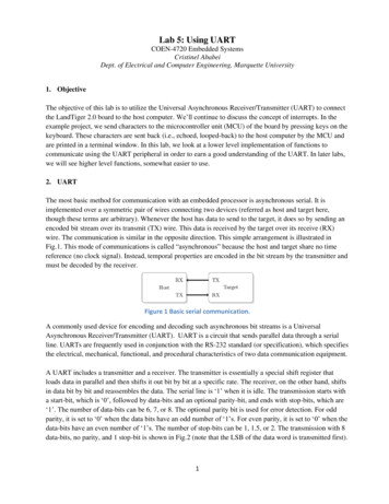
Lab 5: Using UARTCOEN-4720 Embedded SystemsCristinel AbabeiDept. of Electrical and Computer Engineering, Marquette University1. ObjectiveThe objective of this lab is to utilize the Universal Asynchronous Receiver/Transmitter (UART) to connectthe LandTiger 2.0 board to the host computer. We’ll continue to discuss the concept of interrupts. In theexample project, we send characters to the microcontroller unit (MCU) of the board by pressing keys on thekeyboard. These characters are sent back (i.e., echoed, looped-back) to the host computer by the MCU andare printed in a terminal window. In this lab, we look at a lower level implementation of functions tocommunicate using the UART peripheral in order to earn a good understanding of the UART. In later labs,we will see higher level functions, somewhat easier to use.2. UARTThe most basic method for communication with an embedded processor is asynchronous serial. It isimplemented over a symmetric pair of wires connecting two devices (referred as host and target here,though these terms are arbitrary). Whenever the host has data to send to the target, it does so by sending anencoded bit stream over its transmit (TX) wire. This data is received by the target over its receive (RX)wire. The communication is similar in the opposite direction. This simple arrangement is illustrated inFig.1. This mode of communications is called “asynchronous” because the host and target share no timereference (no clock signal). Instead, temporal properties are encoded in the bit stream by the transmitter andmust be decoded by the receiver.Figure 1 Basic serial communication.A commonly used device for encoding and decoding such asynchronous bit streams is a UniversalAsynchronous Receiver/Transmitter (UART). UART is a circuit that sends parallel data through a serialline. UARTs are frequently used in conjunction with the RS-232 standard (or specification), which specifiesthe electrical, mechanical, functional, and procedural characteristics of two data communication equipment.A UART includes a transmitter and a receiver. The transmitter is essentially a special shift register thatloads data in parallel and then shifts it out bit by bit at a specific rate. The receiver, on the other hand, shiftsin data bit by bit and reassembles the data. The serial line is ‘1’ when it is idle. The transmission starts witha start-bit, which is ‘0’, followed by data-bits and an optional parity-bit, and ends with stop-bits, which are‘1’. The number of data-bits can be 6, 7, or 8. The optional parity bit is used for error detection. For oddparity, it is set to ‘0’ when the data bits have an odd number of ‘1’s. For even parity, it is set to ‘0’ when thedata-bits have an even number of ‘1’s. The number of stop-bits can be 1, 1.5, or 2. The transmission with 8data-bits, no parity, and 1 stop-bit is shown in Fig.2 (note that the LSB of the data word is transmitted first).1
Figure 2 Transmission of a byte.No clock information is conveyed through the serial line. Before the transmission starts, the transmitter andreceiver must agree on a set of parameters in advance, which include the baud-rate (i.e., number of bits persecond), the number of data bits and stop bits, and use of parity bit.To understand how the UART's receiver extracts encoded data, assume it has a clock running at a multipleof the baud rate (e.g., 16x). Starting in the idle state (as shown in Fig.3), the receiver “samples” its RXsignal until it detects a high-low transition. Then, it waits 1.5 bit periods (24 clock periods) to sample its RXsignal at what it estimates to be the center of data bit 0. The receiver then samples RX at bit-period intervals(16 clock periods) until it has read the remaining 7 data bits and the stop bit. From that point this process isrepeated. Successful extraction of the data from a frame requires that, over 10.5 bit periods, the drift of thereceiver clock relative to the transmitter clock be less than 0.5 periods in order to correctly detect the stopbit.Figure 3 Illustration of signal decoding.UARTs can be used to interface to a wide variety of other peripherals. For example, widely availableGSM/GPRS cell phone modems and Bluetooth modems can be interfaced to a microcontroller UART.Similarly GPS receivers frequently support UART interfaces.The NXP LPC1768 microcontroller includes four such devices/peripherals called UARTs: UART0/2/3 andUART1. See pages 307 and 327 of the LPC17xx User’s Manual [1]. See also page 27 of the Datasheet [2].UART0 and UART2 of the microcontroller are connected on the LandTiger 2.0 board to the SP3232 (U10on the board’s schematic diagram), which converts the logic signals to RS-232 voltage levels. Thisconnection is realized from pins {P0.2 and P0.3} and { P0.10 and P0.11} of the microcontroller to the pins{9, 10, 11, and 12} SP3232 chip. To confirm this, please take a look at the board’s schematic diagram,provided as file 0 HY LandTiger SCH.pdf (page 6) inside the files archive of lab#2. Also, take sometime to read Section 2.12 of the board’s manual, provided as file1 HY LandTiger v20 user manual v11.pdf (pages 18-19) inside the files archive of lab#2.The SP3232 chip drives the two COM1 and COM2 represented by the two female DB9 connectors on theboard.For more details on UART and RS-232, please read references [1-4].In this lab we will explore serial communication between the (target) LPC1768 UART and a serialcommunication port of the host PC.2
3. Example1: Microcontroller “echoes” back the characters sent by host computer(a) ExperimentIn the first example of this lab, we’ll use an adapted (to the LandTiger 2.0 board) example project thatcomes with the “LPC1700 code bundle” [5]. The LPC1700 Code Bundle is a free software package fromNXP that demonstrates the use of the built-in peripherals on the NXP LPC17xx series of microcontrollers.The example software includes a common library, peripheral APIs, and test modules for the APIs. Theseexamples were put together for ARM’s boards. However, because LandTiger 2.0 board bears a lot ofsimilarities with ARM’s MCB1700 board, most of these examples can be adapted fairly easily to makethem work on the LandTiger 2.0 board. For instance, in this lab we work with an adapted version of theUART/ example from the “LPC1700 code bundle”.All the required source files for this example are located under Example1/ folder that comes with thearchive of files provided for this lab. Create a new uVision project and add all the provided files to yourproject. Before doing anything, first make sure you remove the ISP and RST jumpers of theLandTiger 2.0 board; these are the jumpers marked as JP6 and JP7 on the board, next to the actual COMconnectors.Step 1: Connect the board (COM1) and the host computer using the serial cable.Step 2: Familiarize yourself with the following files:--uart.c: contains the UART0 / UART2 handlers/driver functions--uarttest.c: contains a small test programStep 3: Build the project and download to target.Step 4: Establish a Terminal connectionFirst must make sure you download and/or install a serial connection interface, such as Putty, which youcan download from: http://www.putty.org--Start- All Programs- Putty- Putty--Then, select Connection, Serial and type COM# (check in Control Panel to see what the # should be in yorcase, as the COM port assigned to the attached USB to serial converter). Use a baud rate of 9600, 8 databits, no parity, 1 stop bit, and no flow control.--Click on Session and choose the type of connection as Serial. Save the session for example as "lab4".--Finally, click on Open; you should get the terminal window.Note: You can use other terminal programs such as:Termite (https://www.compuphase.com/software termite.htm ) or Cris’ favorite!TeraTerm tml ) orHyperSerialPort (http://www.hyperserialport.com/index.html ) orRealTerm (http://realterm.sourceforge.net ) orCoolTerm (http://freeware.the-meiers.org ), etc.Step 5: Type some text. The text should appear in the Terminal window. This is the result of: First, whatyou type is sent to the microcontroller via the serial port (that uses a UART). Second, the MCU receives3
that text via its own UART and echoes (sends back) the typed characters using the same UART. The hostPC receives the echoed characters that are displayed in the Terminal.Disconnect the serial cable from the COM1 of the board and connect it to COM2 port on the LandTiger 2.0board. The behavior of project should be the same, as I hope you expected (assuming you read andunderstood the source code).(b) Brief program descriptionLooking at the main() function inside the uarttest.c file we can see the following main actions:--UART0 and UART2 are initialized:UARTInit(0, 9600);UARTInit(2, 9600);--A while loop which executes indefinitely either for UART0 or for UART2. The instructions executedinside this loop (let’s assume the UART0) are: Disable Receiver Buffer Register (RBR), which contains the next received character to be read. Thisis achieved by setting all bits of the Interrupt Enable Register (IER) to ‘0’ except bits THRE andRLS. In this way the LSB (i.e., bit index 0 out of 32 bits) of IER register is set to ‘0’. The role of this bit(as explained in the LPC17xx User’s Manual [1], page 311) when set to ‘0’ is to disable the ReceiveData Available interrupt for UART0. Send back to the host the characters from the buffer UART0 Buffer. This is done only if there arecharacters in the buffer (the total buffer size is 40 characters) which have been received so far from thehost PC. The number of characters received so far and not yet echoed back is stored and updated inUART0 Count. Once the transmission of all characters from the buffer is done, reset the counter UART0 Count. Enable Receiver Buffer Register (RBR). This is achieved by setting to ‘1’ the LSB of IER, which inturn is achieved using the mask IER RBR.(c) Source code discussionPlease take your time now to thoroughly browse the source code in files uart.c and uarttest.c files. Openand read other files as necessary to track the declarations and descriptions of variables and functions.For example, in uarttest.c we see:--A function call SystemInit();This is described in source file system LPC17xx.c. Place the mouse cursor on SystemInit(), then rightclick and select Go to the Definition of ‘SystemInit’. Try to understand how this function is implemented;what each of the source code lines do?--A function call UARTInit(0, 9600);This function is described in source file uart.c. The declaration of this function is done inside the headerfile uart.h. Open these files and read the whole code; try to understand each line of the code.--An instruction:LPC UART0- IER IER THRE IER RLS; // Disable RBRBased on what’s been studied in the previous labs we should know already that LPC UART0 is an addressof a memory location – the UART0 peripheral is “mapped” to this memory location. Starting with thismemory location, several consecutive memory locations represent “registers” associated with thisperipheral/device called UART0. All 14 such registers (or memory locations) are listed on page 309 of the4
User Manual. Utilizing this peripheral is done through reading/writing into these registers according to theirmeaning and rules described in the manual. For example, one of the 14 registers associated with UART0 isInterrupt Enable Register (IER).From a C programming perspective, LPC UART0 is declared inside header file LPC17xx.h:#define LPC UART0((LPC UART TypeDef*) LPC UART0 BASE)Which also declares what LPC UART0 BASE as:#define LPC UART0 BASE(LPC APB0 BASE 0x0C000)Where LPC APB0 BASE is declared at its turn in the same file:#define LPC APB0 BASE(0x40000000UL)This effectively makes LPC UART0 BASE to have value: 0x4000C000, which not surprisingly coincideswith what is reported on page 14 of the LPC17xx User’s Manual!Furthermore, the Interrupt Enable Register (IER) contains individual interrupt enable bits for the 7potential UART interrupts. The IER register for UART0 is “mapped” (or associated with) to memoryaddress 0x4000C004 as seen on page 309 of the LPC17xx User’s Manual. This fact is captured in thestruct declaration of LPC UART TypeDef inside the header file LPC17xx.h (open this file and doublecheck it!). As a result, in our C programming, we can refer to the IER register as in the instruction that weare currently discussing: LPC UART0- IER, which basically stores/represents the address 0x4000C004.In addition, note that IER THRE and IER RLS are declared inside the header file uart.h as:#define IER THRE#define IER RLS0x020x04Which are utilized as masks in our instruction:LPC UART0- IER IER THRE IER RLS; // Disable RBRSo, finally as we see, the effect of this instruction is simply to turn ‘1’ bit index 1 (the second LSB out of 32bits) and bit index 2 (the third LSB out of 32 bits) of the IER register! All other bits are set to ‘0’.Having bit index 1 of this register set to ‘1’ enables the Transmit Holding Register Empty (THRE) flagfor UART0 – see Table 276, page 311 of the LPC17xx User’s Manual. Having bit index 2 of this registerset to ‘1’ enables the UART0 RX line status interrupts. As already said, all other bits are set therefore viathis masking to ‘0’. This includes the LSB (i.e., bit index 0 out of 32 bits) of IER register, which is set to‘0’. The role of this bit (as explained in the LPC17xx User’s Manual on page 311) when set to ‘0’ is todisable the Receive Data Available interrupt for UART0.You should be able now to explain what the following instruction does:LPC UART0- IER IER THRE IER RLS IER RBR; // Re-enable RBRSummarizing, what the code inside uarttest.c does is:--disable receiving data--send back data to the PC from the buffer (i.e., array variable UART0 Buffer)--reset counter of characters stored in buffer--enable receiving dataNote: As mentioned in previous labs, in general, one would not need to worry about these details aboutaddresses to which registers are mapped. It would be sufficient to just know of, for example, the definitionand declaration of LPC UART TypeDef inside the header file LPC17xx.h. To the C programmer, it istransparent to what exact address the register IER is mapped to for example. However, now at thebeginning of this class, it’s instructive to track these things so that we get a better global picture of theseconcepts. It also forces us to get better used with the LPC17xx User’s Manual and the datasheets.Notice that inside the source file uart.c we have these two function descriptions:5
void UART0 IRQHandler (void) {.}void UART2 IRQHandler (void) {.}which are not called for example inside uarttest.c, but they appear inside startup LPC17xx.s:DCDUART0 IRQHandlerDCDUART2 IRQHandlerThe function void UART0 IRQHandler (void) is the UART0 interrupt handler. Its name isUART0 IRQHandler because it is named like that by the startup code inside the file startup LPC17xx.s.DCD is an assembler directive (or pseudo-op) that defines a 32-bit constant.Inside this function, we see a first instruction:IIRValue LPC UART0- IIR;What does it do? It simply reads the value of LPC UART0- IIR and assigns it to a variable whose nameis IIRValue. LPC UART0- IIR is the value of the register IIR (Interrupt IDentification Register identifies which interrupt(s) are pending), which is one of several (14 of them) registers associated with theUART0 peripheral/device. You can see it as well as the other registers on page 309 of the User Manual.Take a while and read them all. The fields of the interrupt register IIR are later described on page 312 in theUser Manual. Take another while and read them all on page 312.Next, inside uart.c we see:IIRValue 1;IIRValue & 0x07;/* skip pending bit in IIR *//* check bit 1 3, interrupt identification */Which shifts right with one bit IIRValue and then AND’s it with 0x07. This effectively “zooms-in” onto thefield formed by bits index 1-3 from the original LPC UART0- IIR, bits which are now in the position bitsindex 0-2 of IIRValue variable.Going on, we find an “if” instruction with several branches:if ({.}else{.}else{.}else{.}IIRValue IIR RLS )/* Receive Line Status */if ( IIRValue IIR RDA )/* Receive Data Available */if ( IIRValue IIR CTI )/* Character timeout indicator */if ( IIRValue IIR THRE )/* THRE, transmit holding register empty */Read Table 277, page 312 in the User Manual to see the meaning of the three bits 1-3 from the original IIRregister:0110101100011 - Receive Line Status (RLS).2a - Receive Data Available (RDA).2b - Character Time-out Indicator (CTI).3 - THRE InterruptFor each of these situations, something else is done inside the corresponding branch of the “if” instructionabove. In other words, we first identify the interrupt, and for each ID we do something else. If none of theexpected IDs is found, we do nothing. Please take your time now to explain what’s done in each of thesecases. Read pages 312 in the User Manual for this. This is very important in order to understand the overalloperation of the example of this lab.6
4. Lab Assignment1) Describe in less than a page (typed, font size 11, single line spacing) all instructions inside thefunction void UART0 IRQHandler (void) for each of the branches of the main “if” instruction.Include this in your lab report.2) Modify Example 1 such that the characters typed on the host’s keyboard are also displayed on theLCD display on the board.5. Credits and references[1] LPC17xx user’s manual; http://www.nxp.com/documents/user manual/UM10360.pdf (part of lab#2archive of files)[2] NXP LPC17xx Datasheet;http://www.nxp.com/documents/data sheet/LPC1769 68 67 66 65 64 63.pdf (also part of lab#2 filesarchive of files)[3]--Jonathan W. Valvano, Embedded Systems: Introduction to Arm Cortex-M3 Microcontrollers, 2012.(Chapters 8,9)--Pong P. Chu, FPGA Prototyping by VHDL Examples: Xilinx Spartan-3 Version, Wiley 2008. (Chapter 7)--Lab manual of course http://www.cs.indiana.edu/ geobrown/book.pdf (Chapter 5)--EE 472 Course Note Pack, Univ. of Washington, 2009,http://abstract.cs.washington.edu/ shwetak/classes/ee472/notes/472 note pack.pdf (Chapter 8)[4] UART entry on Wikipedia (click also on the references therein for RS-232);http://en.wikipedia.org/wiki/Universal asynchronous receiver/transmitter[5] LPC1700 Code Bundle;Download: e.lpc17xx.keil.uart.pdf[6] Pluggable USB to RS-232 DB9 Serial Adapter;Amazon: 2303HXChipset/dp/B00425S1H8/ref sr 1 1?ie UTF8&qid 1359988639&sr 81&keywords plugable usb to serialTigerdirect: s/itemdetails.asp?EdpNo 3753055&CatId 4647
1_HY_LandTiger_v20_user_manual_v11.pdf (pages 18-19) inside the files archive of lab#2. The SP3232 chip drives the two COM1 and COM2 represented by the two female DB9 connectors on the board. For more details on UART and RS-232, please read references [1-4]. In this lab we will explore serial communication between the (target) LPC1768 UART and .