Transcription
uPrint SE and uPrint SE Plus Personal 3D PrintersUser Guide209226-0001
Legal NoticeThe only warranties for Stratasys products andservices are set forth in the express warrantystatement accompanying such products andservices. Nothing herein should be construedas constituting an additional warranty.Stratasys shall not be liable for technical oreditorial errors or omissions contained herein. 2011 Stratasys Inc. All rights reserved.Stratasys, Dimension, uPrint, Catalyst, FDM,Dimension BST, Dimension SST, WaveWash,and Ecoworks are registered trademarks ofStratasys Inc. FDM Technology, FusedDeposition Modeling, ABSplus, Catalyst EX,and Smart Supports are trademarks ofStratasys, Inc. All other trademarks are theproperty of their respective owners, andStratasys assumes no responsibility with regardto the selection, performance, or use of thesenon-Stratasys products. Product specificationsare subject to change without notice. Printed inthe USA.
Table of Contents1 Introduction.1How to use this guide .1Learn More!.1Safety precautions .22 Overview .3Finding more information .93 Setup .10Installing software .10Networking the printer .10Establishing network communication with the printer .11Installing System Software on printer.14Adding the second Material Bay .144 Operation .19Display panel and keypad.19System software overview.20CatalystEX overview .21Processing your STL file for printing .22Building a part .24The display panel during build.25Chamber Lights .25Pausing a build .25Resuming after pause.25Canceling a build.26Removing a completed part .26Removing support material .27Emptying the purge bucket .27Replacing material for single material bay.28Replacing material for dual material bays .29Material bay LEDs .30Replacing material spools.30Storing material spools.30Auto power down .32Powering off .32Resuming operations from Standby mode .33Updating printer system software:.33i
5 Maintenance .34Startup kit tools . 34Preventive Maintenance . 34Daily .34500 Hour maintenance . 35Tip wipe assembly.35Tip shield replacement .37Remove debris from the Filament Present switch .402000 Hour maintenance . 41Tip replacement and calibration .41Chamber light bar replacement.476 Troubleshooting .48Troubleshooting .48Fault determination codes.49Exporting printer configuration (.cfg) file .49Cycling power .50Diagnosing loss of extrusion .50Clogged tip .51Material Jam.52Recovering from loss of extrusion.547 Support.58Registration .58Customer Support.588 Recycling .59Removing the EEproms from the material guides.60Removing the desiccant from the material spool .609 Printer Specifications .61Physical specifications.61Facility specifications .61Workstation specifications.62Power specifications .62Environmental specifications .62Acoustic specifications .6210 Supplemental Information.63Stratasys Limited Warranty Statement .63Declaration of Conformity .65Regulatory and environmental information .6611 Appendix. A1Uninterruptible Power Supply (UPS) Use and Installation. A1ii
1IntroductionuPrint SE and uPrint SE Plus are designed with ultimate simplicity in mind. The printer enables youto build parts quickly and easily, even if you’ve never used a 3D printer before.The printers build models with ABSplusTM material so parts are strong and durable. ABSplus materialalso ensures you will be able to drill, tap, sand and paint your creations. With Soluble SupportTechnology (SST), your completed parts are quickly available for review and test. uPrint SE anduPrint SE Plus are an innovative combination of proprietary hardware, software and materialtechnology.Welcome to the new dimension of 3D modeling!How to use this guideThis User Guide is laid out in easy to follow sections which cover Set-up, Operation, Maintenance,and Troubleshooting. Read each section carefully so that you will get the best performance fromyour printer.Throughout this User Guide, text representing Interface Messages that appear on the display panelare presented in a bold font.Learn More!An electronic User Guide is available on the startup CD. This guide provides information on thefollowing topics: Troubleshooting informationImportant safety notices and regulatory informationInformation about supported printing suppliesDetailed user instructionsYou can also find more information at:http://www.uprint3dprinting.com1
Safety precautionsThe following precautions ensure the proper use of the printer and prevent the printer from beingdamaged. Follow these precautions at all times. Use the power supply voltage specified on the nameplate. Avoid overloading the printer’selectrical outlet with multiple devices.Ensure the printer is well-grounded. Failure to ground the printer may result in electrical shock,fire and susceptibility to electromagnetic interference.Before disassembling or repairing the printer yourself, contact your local ServiceRepresentative. See Support section of User Guide.Use only the power cord supplied with the printer. Do not damage, cut or repair the powercord. A damaged power cord has risk of fire and electric shock. Replace a damaged powercord with an approved power cord.Do not allow metal or liquids to touch the internal parts of the printer. Doing so may causedamage, fire, electric shock or other serious hazards.Power off the printer and disconnect the power cord from the power outlet in any of thefollowing cases: If there is smoke or an unusual smell coming from the printer. If the printer is making an unusual noise not heard during normal operation.A piece of metal or a liquid touches the internal parts of the printer.During an electrical (thunder/lightning) stormDuring a power failureThe following classifications are used throughout this guide.CAUTION: Indicates a potentially hazardous situation which, if not avoided,may result in minor or moderate injury.WARNING: Indicates a potentially hazardous situation which, if not avoided,could result in serious injury.Hot Surface: The hot surface sign indicates the presence of devices with hightemperatures. Always use extra care, and wear safety gloves, when workingaround heated componentsGloves: When performing some maintenance procedures, the machine maybe hot and gloves will be required to avoid burns.Safety Glasses: Wear safety glasses to avoid injury to your eyes.Lifting Hazard: Lift with two or more people to avoid serious injury.Recycle: Use proper recycling techniques for materials and packaging.ESD: Use standard electrostatic discharge (ESD) precautionswhen working on or near electrical components.2
2OverviewuPrint SE and uPrint SE Plus build models from CAD STL files. The printer builds three-dimensionalparts by extruding a bead of ABS material through a computer-controlled extrusion head, producinghigh quality parts that are ready to use immediately after completion.uPrint SE and uPrint SE Plus consist of two primary components — the 3D printer and material bay.Catalyst EX is the preprocessing software that runs on Windows XP Pro, Windows Vista orWindows 7 platforms.uPrint SE builds a maximum part size of 203 x 152 x 152 mm (8 x 6 x 6 in). uPrint SE Plus builds amaximum part size of 203 x 203 x 152 mm (8 x 8 x 6 in). Each material carrier contains 688 cc(42 cu. in.) of usable material — enough to build continuously for about 67 hours without reloading.You can add an optional second material bay for extended build times.3
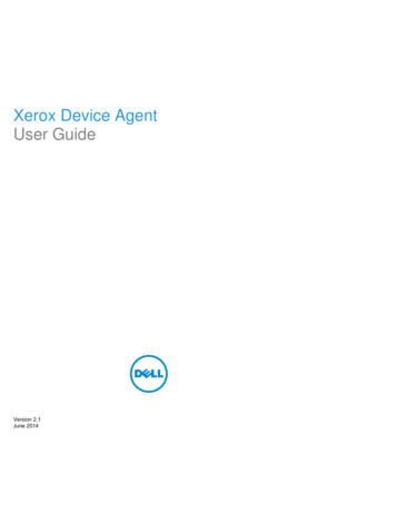
Figure 1 Front and left side view of printer.1625341Display Panel2Material Bay, Support Side3Optional Material Bay, Support Side4Optional Material Bay, Model Side5Material Bay, Model Side6Power ON/OFF Switch4
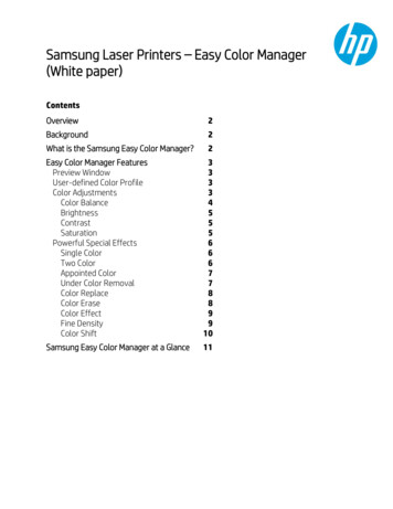
Figure 2 Interior chamber - front view1293876451Extrusion Head2Tip wipe assembly3Purge bucket4Z stage platen5Modeling base retainers (x2)6Modeling base7Z stage guide rods8Z stage lead screw9Extrusion Tips5
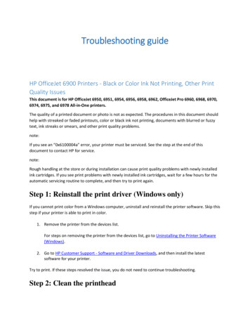
Figure 3 Rear view of printer819102113124135146157161Model Material Y Connector9Support Material Tube2Model Material Tube10UPS Connection3AC Power Cord Connector11Material Bay Cable Connector4Circuit Breaker12RJ-45 Network Connector5Material Bay13Diagnostics Cable Connector6Optional Model Material Tube14Material Bay Communications Cable7Optional Material Bay15Optional Material Bay Communications Cable8Support Material Y Connector16Optional Support Material TubeNote: To avoid damage to the printer from an uncontrolled power loss,installation of a UPS (Uninterruptible Power Supply) is recommended.6
Figure 4 Material carriersModel material carrierSupport material carrierFigure 5 Modeling baseModeling baseCAUTION: DO NOT reuse modeling bases. If a modeling base is reused,calibration errors, poor part quality, and loss of extrusion may occur.Additional modeling bases are available from your reseller.7
Figure 6 Startup Kit contents1Gloves2Power cord (Euro)3Power cord (US)4Crossover cable (orange)5Network cable (blue)6Tip replacement kit (A. Support tip B. Model tip C. 8 Tip shields D. 4 Tip wipe assemblies)710x magnifier loupe8Wire brush9Cutters101/8 inch T-Handle wrench (red)117/64 inch T-Handle wrench (yellow)12Needle nose pliers13Model material spool14Support material spool15CatalystEX CD16System Software CD17User Guide CD8
Finding more informationCatalystEX Online HelpSimple operatinginstructions for CatalystEXare available in CatalystEXDynamic Help. You canalso see CatalystEX Helpfrom the menu bar Help ContentsWorld Wide WebAdditional information is available at:http://www.uprint3dprinting.com9
3SetupSet up the printer and material bay(s) per assembly instructions included with printer.Installing softwareThere are two software programs that work with uPrint SE and uPrint SE Plus:1.CatalystEX, installed on your workstation, processes the STL files for printing and communicateswith the printer from your workstation.2.System software, the operating software installed on the printer, controls printer functions.Installing CatalystEX:1.Locate the CatalystEX CD from startup kit and insert into workstation (PC).2.Click the Install CatalystEX: button.3.Follow prompts to finish loading CatalystEX on the workstation.Installing system software to the workstation:1.Locate the System Software CD from startup kit and insert into workstation (PC).2.Click the Install software button to load system software to your workstation. You will be askedto load this system software to your printer later.3.Follow prompts to finish installing system software on the workstation.4.Install system software to the printer, see “Installing System Software on printer” on page 14Networking the printerThere are two methods of connecting your printer to your workstation, over a network or with adirect connection to your workstation.Connecting through a network:1.Locate the network cable (blue) from the startup kit.2.Connect the network cable between the printer and the network hub.3.Establish communication, see “Establishing communication on a dynamic network:” on page11 if you have a dynamic network, or see “Establishing communication on a static network:”on page 11 if you have a static network.Connecting directly to a workstation:1.Locate the crossover cable (orange) from the startup kit.2.Connect the crossover cable between the printer and the network port on your workstation.3.Establish communication, see “Establishing communication on a static network:” on page 1110
Establishing network communication with the printerYou will need to establish network communication between your workstation and printer beforeyou can send files to be built. How you establish this communication with an IP address isdependent upon how your network and workstation are configured. If your network is configuredfor DHCP (Dynamic Host Configuration Protocol), your DHCP server will automatically assign aDynamic IP address to your printer. This is the default setting for your printer and commonly used inlarge networks. In some situations you may need to manually enter a Static IP address for yourprinter and record the IP address in the CatalystEX software. Static IP addresses are frequentlyused for smaller networks or for direct connection between your workstation and printer. Follow theinstructions below to configure your workstation and network.Establishing communication on a dynamic network:If you are on a dynamic network (or not sure of your network type) follow these steps to allowCatalystEX to find your printer and establish communication.1.Connect a network cable between the printer and a network hub.2.Make sure the printer is ON and determine the Unique Device Name (UDN) for your printer.a.From Idle (or Ready to Build), press Maintenance on the displaypanel. The display will show Maintenance and the software version.b.From the display panel press System.c.From the display panel press Set Network. The top window willdisplay: Network Admin - Dynamic IP Address; UDN.d.The Unique Device Name (UDN) for your printer is listed here. Thisis preset at the factory and cannot be changed.3.From your workstation, start the CatalystEX.4.From the General tab, click the Manage 3D Printers button.5.Click the Add from Network button in the lower right corner of the window.6.A new window, Add 3D Printer, should list your printer in the main window (identified by itsUDN). Click on the printer in this window and enter a name and location in the lower portionof the window.7.Click Add Printer and you are ready to print. Close the Add 3D Printer window.Note: If your printer is not displayed in the “Add 3D Printer” window, you arenot using a dynamic network and you will need to set up a static networkaddress.Establishing communication on a static network:If you are using a static network or connecting the printer directly to a workstation, you will need toenter the static IP address information into the workstation and the printer. If you are using a staticnetwork and your computer already has network access, see “Setting the static network on printer:”on page 131.Set the static IP address information in the workstation:a.For Windows XP, see “Setting the static network in Windows XP:”on page 12b.For Windows Vista, see “Setting the static network in WindowsVista:” on page 12c.For Windows 7, see “Setting the static network in Windows 7:” onpage 122.Set the static IP address information in the printer, see “Setting the static network on printer:”on page 133.Establish communication, see “Establish communication:” on page 1311
Setting the static network in Windows XP:1.From your workstation open the Control Panel and double click on Network Connections.2.Right click on Local Area Connection and then left click on Properties.3.Select Internet Protocol (TCP/IP) from the list.4.Click on the Properties button.5.Click on the Use the following IP address option.6.Enter the IP Address, Subnet Mask and Default Gateway. Contact your IT Administrator orInternet Service Provider for details regarding IP address information. The IP address should bedifferent from the workstation, the default gateway and subnet mask should match theworkstation. Enter the IP address, default gateway and subnet mask.7.Click on the OK button when finished. Close any open networking windows.Setting the static network in Windows Vista:1.From your workstation click on the Start Menu.2.Click on the Control Panel button.3.Double click on Network and Internet.4.Double click on the Network and Sharing Center icon.5.Left click on Manage network connections.6.Right click on the Local Area Connection icon then left click on Properties.7.Select Internet Protocol Version 4 (TCP/IPv4) from the list.8.Click on the Properties button.9.Click on the Use the following IP address option.10. Enter the IP address, Subnet Mask and Default Gateway. Contact your IT Administrator orInternet Service Provider for details regarding IP address information. The IP address should bedifferent from the workstation, the default gateway and subnet mask should match theworkstation. Enter the IP address, default gateway and subnet mask.11.Click on the OK button when finished. Close any open networking windows.Setting the static network in Windows 7:1.From your workstation click on the Start Menu.2.Click on the Control Panel button.3.Double click on Network and Internet.4.Double click on the Network and Sharing Center icon.5.Double click Local Area Connection.6.Click on the Properties button.7.Select Internet Protocol Version 4 (TCP/IPv4) from the list.8.Click on the Properties button.9.Click on the Use the following IP address option.10. Enter the IP address, Subnet Mask and Default Gateway. Contact your IT Administrator orInternet Service Provider for details regarding IP address information. The IP address should bedifferent from the workstation, the default gateway and subnet mask should match theworkstation. Enter the IP address, default gateway and subnet mask.11.Click on the OK button when finished. Close any open networking windows.12
Setting the static network on printer:1.Obtain your static network address from your Network Administrator.2.From Idle (or Ready to Build), press Maintenance on the display panel. The display will showMaintenance and the software version.3.Press System.4.Press Set Network. The top window displays: Network Admin - Static IP Address; UDN.5.Press Static IP to display default settings.IP Address:172.016.075.020 or 198.000.000.001NM Address:255.255.000.000GW Address:172.018.100.002Note: These values are the factory defaults and MUST be changed. If thesevalues are not changed the printer will continue to restart until they arechanged.Note: The IP address should be different from the workstation, the defaultgateway and subnet mask should match the workstation. Enter the IP address,default gateway and subnet mask.6.Update the IP address:Press Increment to increase the value one digit at a time.Press Next Digit to move the cursor one place to the right.Press Last Digit to move the cursor one place to the left.7.Use the three functions listed above to set your IP address.8.After setting the final digit of the Internet Protocol (IP) address, move the cursor one more placeto the right. The cursor moves to the Netmask (NM) address. Follow the same steps for settingthe Netmask (NM) and Gateway (GW) addresses.9.When you have finished setting the addresses, press Done. The display will show: Change IP,Netmask and Gateway?10. Press Yes. The panel then displays Resetting Network.11.Press Done until Idle is displayed.Establish communication:1.2.From your workstation, start CatalystEX.a.From the General tab, click the Manage 3D Printers button.b.Click the Add from Network button in the lower right corner of thewindow.c.A new window, Add 3D Printer, should list your printer (identifiedby its UDN). Click on the printer in this window and enter a nameand location of your choice in the lower portion of the window.d.Click Add Printer to complete. Close the Add 3D Printer window.If your printer is not displayed in the Add 3D Printer window, you will need to add the printerIP address manually.a.From the General tab, click the Manage 3D Printers button.b.Click the Add Manually button in the lower right corner of thewindow.c.In the Add 3D Printer window, enter a name and location of yourchoice in the appropriate fields.13
d.Enter the IP Address for your printer in the appropriate field. It willbe the same address as entered in step 6.e.Select your printer type from the drop down list, either uPrint SE oruPrint SE Plus.Note: If you only have one printer connected, it will be the only printer in thelist.f.3.Click Add Printer and close the Add 3D Printer window.If you are unable to connect the printer to your workstation, contact your NetworkAdministrator.Installing System Software on printer1.From the display panel, press Maintenance.2.Press System.3.Press Load Upgrade. “Send upgrade from workstation” and the printer IP address will bedisplayed.4.From your workstation, open the CatalystEX by double clicking on the CatalystEX icon.5.Click the Printer Services tab.6.Select your printer from the drop down list then click the Update Software button.7.Navigate CatalystEX to the directory where the system software file is located and select theuPrintSE.upg file for uPrint SE or select the uPrintSEPlus.upg file for uPrint SE Plus. Systemsoftware will now begin to download to the printer.Note: Default uPrint SE system software location for 32 bit systems:C:\Program Files\Dimension\uPrint SE version Default uPrint SE system software location for 64 bit systems:C:\Program Files (x86)\Dimension\uPrint SE version Default uPrint SE Plus system software location for 32 bit systems:C:\Program Files\Dimension\uPrint SE Plus version Default uPrint SE Plus system software location for 64 bit systems:C:\Program Files (x86)\Dimension\uPrint SE Plus version 8.When system software verification is complete, the printer display will show Reboot tocomplete upgrade? Press Yes. The printer will then load the system software then reboot andreturn to Idle.Note: Loading system software will take approximately 10 minutes.Adding the second Material BayYou have the option of adding a second material bay to extend printing times without having toreload material while the model is printing.Installing the Material Bay:1.Remove the Material Bay, material bay cable, material spools and material carriers from thebox.2.Unload the model and support material from the printer.14
3.Open the material bay doors by gently pressing in to release and pulling outwards.4.Remove the material carriers by first pushing them in to unlatch and then pulling themoutwards.5.Place the carriers on a flat stable surface.CAUTION: Do not push the material through the material guide back into thecarrier, doing so can cause material to break or become tangled.6.Open the carriers.7.Rotate the spools to rewind the material, leaving 2 inches (50mm) remaining at the materialguide. See Figure 7.Figure 7 Rewinding the material spool8.Using a cutters, cut the excess 2 inches (50mm) of material from the material guide. leaving ablunt end.9.Power the printer off at the power switch.10. When the display is blank and the printer has shut down, turn the circuit breaker to the OFFposition.11.Disconnect the power cable, network cable, material bay cable and UPS cable if used.12. Disconnect the model and support material tubes from the printer and the material bay bypressing in on the coupler ring and pulling the tubes outward.13. With 2 people, use the handgrips to lift the printer off of the material bay and place on a flatstable surface. See Figure 8.Figure 8 Separating the printer and material bay14. Position the second material bay on top of the existing material bay. Be sure the feet and pinsare properly aligned. See Figure 9.15
Figure 9 Positioning material bays15. With 2 people, position the printer on to the top of the material bays. Be sure the feet and pinsare properly aligned. See Figure 10.Figure 10 Positioning printer16. Remove the black plugs from the model and support Y blocks by pushing in on the couplerrings and pulling outward.Figure 11 Removing the Y block plugs17. Connect the short red striped material tube (M1) from model (M) coupler of upper material bayto left side of model Y block by inserting firmly into red couplers
1 1 Introduction uPrint SE and uPrint SE Plus are designed with ultimate simplicity in mind. The printer enables you to build parts quickly and easily, even if you’ve never used a 3D printer before. The printers build models with ABS plusTM material so parts are strong and durable. ABS plus material also ensures you w