Transcription
30th European Conference on Acoustic Emission Testing & 7th International Conference on Acoustic EmissionUniversity of Granada, 12-15 September 2012www.ndt.net/EWGAE-ICAE2012/Developing an Acoustic Emission Measuring System Based on ModularHigh Speed Data Acquisition DevicesGabor POR 1,2, Laszlo DOSZPOD1, Tibor DOBJAN1,2, ,1MAID Laboratory, College of Dunaujvaros; Dunaujvaros, HungaryPhone: 36 30 999 0360, Fax: 36 2551 904906; e-mail: porg@mail.duf.hu2Institute for Mechanical Engineering, College of Dunaujvaros, Dunaujvaros, HungaryAbstractToday fast data sampling capabilities of electronics enables to produce not only the traditional AE parameters,but we can sample and record the whole signal. This opens the way to spectral estimation and other dataevaluation techniques. We present a system based on LABVIEW programming of National Instruments devices.We introduce a new event detection technique based on sequential probability ratio test. Using embedded systemwe can carry out fast sampling and only the necessary part of the data is transferred to the main computer, wheremore developed methods like wavelet spectrum estimation, skeleton method and a neural network based onMATLAB are used to classify events.Keywords: Acoustic Emission measuring technique, SPRT, data base, data processing, clustering, skeleton,artificial intelligence methods1. IntroductionTraditional Acoustic Emission (AE) measuring technique uses still parameters, which hadbeen developed when the electronics could not handle the necessary data sampling rate fordirect measurement of the acoustic signals. Early electronics of AE systems could typicallycompare the voltage levels. This is why the traditional AE parameters like starting time, risetime, duration and counts had been introduced and are used even today. When the signal levelexceeds the threshold level, it is considered as the beginning of the AE event. The maximumvalue of the signal, i.e. the peak value can be measured just charging a capacitor. The timebetween the beginning and the peak is the rise time. This can be measured as the time lengthof the growing RMS value, i.e. positive derivative of the short time RMS s well. The lattercould be just measured as the integral of the square function of the original signal. Durationdetermined when the RMS value crosses the threshold level back. Finally the oscillation wasestimated by number of the zero level crossing of the original signal and generally calledcounts.Gradually AE systems became a digital system, which means that they start with sampling.All the parameters listed above, today are estimated from digitalized data. But from those wecould estimate other parameters as well. Today fast sampling digital devices are achievable.In AE measurement typically resonance sensors are used with resonance frequency 150 kHzor 450 kHz. In such case a few MHz sampling rate can be sufficient to describe totally thesignal. In case of higher resonance frequency or in case of wideband sensors higher samplingrate necessary. However, today even GHz sampling is achievable. This opened the way toinclude new parameters in data processing and interpretation. First of all FFT based spectrumestimation became possible, but today one can easily map the change of the frequencycontents during a single event using wavelet technique as well. Why most of the AEmeasuring systems still use the traditional parameters? It is partially due to historical reason.There are also some standards claiming to measure those parameters and to draw conclusionfrom those.
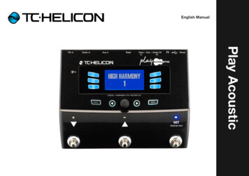
However, there are technical problems as well when applying high sampling rate. First of allwhen the sampling rate is about 1 MHz or above of that, the number of samples is too high tobe stored. It occupies too much memory and the data transfer might be time consuming. It isworth to reduce the data preserving only those parts, where AE events (hits) can be found.This claims a new approach to event recognition what we shall present in Section 2.2Ones all time data have been sampled spectral estimation as well as wavelet technique opensnew possibilities in selecting parameters for classification of AE events. We introduced alsoskeleton method and neural network technique to classify AE events and to recognise what ishappening in investigated materials.2. Sampling and event detection in an embedded systemThe basic aim was to improve the recognition of AE events and to reduce amount of saveddata. In typical AE measurement events are relatively rare, they occupies typically less than10% of the total measuring time. We decided it is a good way to select the events just aftersampling and save only those time segments where we have events. For this reason we useembedded systems. In the embedded system we carry out fast sampling procedure.We use two types of devices depending on application. The following table shows thecomparison between them.Table 1. Comparison of two hardware possibilities used in embedded system partDevicessampling rateprocessing speedscalabilityPXIbigger (2 MHz)slowerhighFPGAsmaller (1 MHz)quickerlowImmediately the sampled signals are tested in the embedded system by a powerful sequentialtest (SPRT) described in Section 2.2. Recognised events are transferred to the other (host)computer and saved there in a database. All the post processing (data processing) takes part inthis second basic computer including the classification, spectral estimation and artificialintelligence for event cause and localisation.2.1 Sampling in different subsystems2.1.1 Sampling using a PXIThe embedded system was built on the basis a PXI of National Instruments. A fast samplinghas been programmed in using LABVIEW, which is a standard programming language ofNational Instruments devices.On the block scheme (fig.1) the blue colors means the hardware devices and the orange colormarks software components. The NI – 6115 is a high speed data acquisition hardware. TheNI-PXI 8108 serves as processor unit of the embedded target. NI- PXI 1041 is the powersupply unit of the embedded part. NI-RT (National Instruments - Real Time) was selected forthe operation system of our measuring device. We made software in LABVIEW to store thehigh-speed acquired data in the disk of NI-8108. The data can be downloaded trough FTP to aPC.
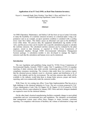
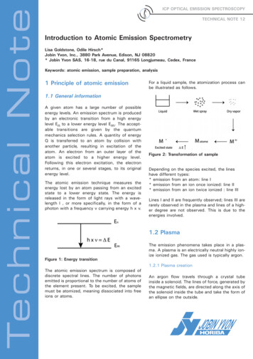
Figure 1. Block scheme of the target systemData sampling is carried out by 2MHz in embedded PXI. Data are split into separate files of170MByte size and transferred to main (host) computer in every 10 second if an event hasbeen found using method described in section 2.2Figure 2. Sampled time signals (upper curves) and the results of their lambdafunction produced by SPRT algorithm (described in Section 2.2) in bottom picturesshowing very precisely the beginning and the end of burst signal buried in highbackground noise2.1.2 Sampling using an FPGAThe FPGA is abbreviation of field-programmable gate array, which means the chip containslogical gates; we can define the function on them and the links between the gates. This way achip can be built which defines the relations between the inputs and the outputs like a wiredelectronic. By the FPGA architecture one can reach faster I/O response times, and specializedfunctionality which is an important requirement in our high speed sampling and processingsystem. This opens the way to organize even faster sampling and recognition procedures.
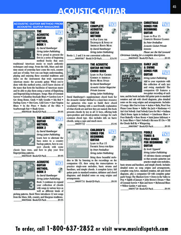
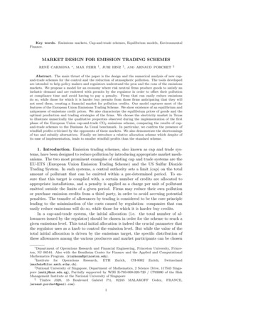
Figure 3. Showing the typical arrangement of FPGA- Figure 4. Acoustic emission sensors, amplifiers and AED32/40Our hardware consists of a traditional set of AE sensors, preamplifiers driven by ourtraditional system (AED-40). But sampling and recognition system is programmed on newhardware elements, from National Instruments shown on fig.5. We chose a NI 9074 typecompact RIO chassis and a NI 9221 type data acquisition module to sample the acousticemission signals. We prepared all the programs in LABVIEW environment.Figure5.Hardware elements 9074 C-RIO chassis9221 DAQ moduleThe main method for the event detection here will be also the SPRT after the AR filtering ofthe signal (see fig.6).
Figure 6. Block scheme of the system developed using FPGAParallel with the SPRT method we estimate the auto power spectrum and the correlationfunctions of the signals which are requisite the filtering and identification of the events. Wecan distinguish the signals of the true acoustic events and electronic or mechanical noise.2.2 Sequential probability ratio test for event detectionThe traditional way of finding the beginning of the event has several drawbacks. When theoriginal time signal exceeds the threshold level, then typically a decision is taken about thebeginning of the events. When we set the threshold level too low, then the probability that thetime signal exceeds that due to statistical disturbances is relatively high. This is the first ordererror. Contrary, if we set the threshold level too high, then the time set of the beginning isdelayed with some systematic error. Also a second order error can be committed if thedecision is not taken.Sequential probability ratio test invented by Wald in 1947 [1] is the best method to reduceboth errors to possible minimum. It gives the certainty of decision making and it enables us toestimate the real beginning of the event with the possible highest precision. All this ismathematically proven [2]. We apply this method to find the AE events. Mathematically thismeans we are using lambda function defined on the following way:(1)Here the denominator is the conditional probability that sampled data x1, xN belong to AEevent (to H1 hypothesis characterized by its distribution which described by the statistics ofAE events), while probability in the nominator means that sampled data x1,x2, xN belong tothe distribution characterized by the background statistics (H0 hypothesis). Since we hadpointed out [3] that AE event belongs to gamma distribution, while the background follows
the traditional Gauss distribution, it is possible to detect events, even, if their amplitude issmaller than the background rms level! This opens the way to discover hidden evens, buriedinto background. Thus our system will produce more event-detection, than any other.Once the event has been found there is a mathematical formula [3] to find the beginning of theevent well before its level exceeds the average background level. This improves the time setof the beginning of the event, which improves the localisation as well.Once the event has been recognised, this time block containing the event and somepreliminary background part and post background parts are transmitted to the data collectionand data processing computer with time stamps. All the other time segments are discarded(except of some background sample collection time to time). This reduces the size of the datasets to be saved for the post-processing.3. Examples of recorded data by the new systemTo test the program we carried out measurements on Gleeble 3800 termo-mechanical physicalsimulator. We recorded the acoustic events generated under cooling of a tensile testspecimen[6].3.1 The case of several events and background noisesThe measuring system allows to change parameters, like the ratio of RMS of the event and thebackground, all parameters of the Autoregressive modelling (AR), which are used for filteringthe original signal as preparation for SPRT.Figure 7. Time signal (above), its on-line spectrum (in the middle) and lambda function (inthe bottom) serving for finding events in high background noises from the screen of ourmeasuring system
On fig.7. we present the screen of our measuring program with a time signal, its on-linespectrum and the lambda function. It is worth to look all the positive values of the lambdafunction (bottom). When they reach the preselected positive decision-making level (in thepresent case 2.3, which ensures 10% of uncertainty in decision-making), then we concludethat there were events different from background in the original time signal. All those parts inlambda function start with relatively sharp, definite profile that means we can precisely set thebeginning of the event. Note on fig.7. that event of different length (duration) can be preciselymarked.3.1 The case of rare events with high uncertaintyFigure 8. Here we had less events, but we also set the decisionmaking to high levelFig.8. present another case, when we hade relatively rare events. Decision-making was set to8.9, which means that decisions were taken with uncertainty of 0.1%. Events which did notreach that level of uncertainty (for example the small event at 0.17113 sec) remainedunnoticed.4. Intelligent process evaluation techniques4.1 Neural network for classification4.1.1. Description of the neural networkTo classify the input parameters of AE we proposed neural network LVQ (Learning VectorQuantization, fig.9). The neural network consists of two layers: a hidden (competing layer)and a linear output layer. Our neural network had 12 neurons in a competitive layer and 2neurons in output layer, which corresponds to two types of recognizable signals. Creating andtraining the neural network was carried out using the MATLAB package [4].
Figure 9. Structure of the LVQ neural networkNeural network can be trained in one of two learning algorithms: training and adaptation. Inthe case of adaptation of the input vector of neural network provided in the order they arepresented to the user(teacher), and in the case of training - at random. Training method usedin practice more often, which was our choice as well.Thus, the algorithm for constructing a program for training the neural network can berepresented as follows (fig. 10).Figure 10. Algorithm for creating and training a neural networkIt should be noted that the division of signal sources in two classes is not optimal because ofthe inability to recognize any other different from AE events and background. However, ourwork is devoted to determine the feasibility of identification of sources of AE signals using
neural networks. In the future, basis of signals from sources different of AE must besignificantly expanded.Input parameters were chosen as follows: the signal amplitude, the total number of pulses,signal rise time, duration and relative energy. Thus, given the number of sensors (4 sensors)and a specified set of features (5 features) a vector of 20 values was fed into the input of theneural network.Specified neural network belongs to a class of networks whose training is done by the teacher.Therefore, the experimental data were divided into two groups. First group was used to createand train the neural network, the second one to test its efficiency. Neural network trainingstopped after 47 cycles and the learning error was zero. Training vectors were recognizedwithout any errors. Results of recognition re of these experiments, which did not participate intraining the neural network, are shown in Figure 11. The chart shows that the AE sources usedare recognized by the neural network with a common mistake, which does not exceed 24%(ratio of correctly recognized units to the total number). This is a relatively high error, but itshould be noted that its significant reduction is possible with increasing database ofexperiments and increasing the size of the vector instruction.Figure 11. Recognition results of the experimental data trained neural network4.2 Skeleton methodWe used skeleton method[5] to extract parameters needed for classification of events frommeasured and processed data. Based on the APSD (Auto Power Spectrum Density Function),we constructed a binary image, where each density value corresponds to a black line in thepicture. The column size in the picture equals to the amplitude at the given frequency in theAPSD.Thinning is a frequently used method for extracting skeleton like shape features[5]. Since,there is no cavity in the picture produced from spectrum, thinning algorithms producescenterlines without any closed curve segments. Moreover, the peaks of APSD function arerepresented by skeletal branches. To find the main frequency components, we removed thebasic branch from skeletal curve in the bottom (see grey branches on fig.12). By this way, we
get individual, separated branches, corresponding to the main frequency components of thespectrum.From the spectrum one can extract features partitioning it into ranges with the same size (seefig.12) The drawback of such conventional partitioning is that it may split the peaks.Figure 12. The traditional, static spectrum separationWith the help of the skeletal branches, we can partition the spectrum dynamically. First, webuild skeleton using thinning method. Then we cut the basic line of the skeleton tree, thus weget separated branches as it is shown on fig.13 by grey branches. We chose the separators atthe position of the global minimum between neighboring skeletal branches. This algorithmcannot cut important peaks.Finally, RMS value between separators are estimated and used for training and recognition.Figure 13. The new, dynamic spectrum separation
5. SummaryOur new AE measuring system presented here has several advantages. First of all it selectsevents using SPRT. This enables to set the uncertainty level beforehand, it finds events buriedin the high background, and it can find more precisely the real onset of the events. Embeddedsystem for sampling and the SPRT event selection reduces the total data amount to be saved,which allows to use very high sampling rate without the needs to high data storages.All these premises open the way to find the average spectrum of events and backgroundseparately. It became also possible to analyse the time dependent spectral components ofseparate events using wavelet technique.However, this produces hundreds and thousand of parameters if we would use all spectral dataand time-frequency atoms. Therefore there is a need for intelligent classification algorithms.We found the skeleton method to be handsome for selecting a few dozens characterizingparameters from estimated spectrum, and we are introducing neutral network for handling thelarge data base and for classification of new events.Ideas described in this paper have been tested in tensile test, ECAP test [6] and in AE testduring heating and cooling of TRIP and Co-Mn steels [7]AcknowledgmentsThis work was supported by Hungarian grant TÁMOP 4.2.2. Neural network was developedby Andrei PIRUMOV from National Technical University of Ukraine "KPI", Kiev, Ukrain,working as guest researcher in MAID Laboratory of College of Dunaujvaros.References1. A Wald: ‘Sequential Tests of Statistical Hypotheses’, Annals of MathematicalStatistics, Vol. 16, No 2, pp 117-186 (1947)2.G. Szappanos, G. Por: Basic Ideas and Realization of Completely Digitised Loose PartDetection System HELPS, Progress in Nuclear Energy, vol. 34, No3, pp.195-201,(1999)3. G. Szappanos, G. Por: Improvements in the Theory of Identification of Burst-ShapedEvents for Fault Diagnosis, Nuclear Science and Engineering, vol. 13, pp. 261-267,(1999)4. Медведев В.С., Потемкин В.Г. Нейронные сети. MATLAB 6. – М.: ДИАЛОГМИФИ, 2002. – 496 с.5. K. Siddiqi, S.M. Pizer (Eds.), Medial Representations – Mathematics, Algorithms, andApplications,Series in Computational Imaging, Springer, 2008.6. G. Por,,et al: Acoustic Emission during tensile tests and ECAP paper presented at thisconference7. G. Por et al.:Acoustic Emission from transformation of the textures of TRIP steel paperpresented at this conference
National Instruments devices. On the block scheme (fig.1) the blue colors means the hardware devices and the orange color marks software components. The NI - 6115 is a high speed data acquisition hardware. The NI-PXI 8108 serves as processor unit of the embedded target. NI- PXI 1041 is the power supply unit of the embedded part.