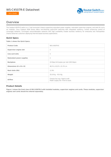
Transcription
W5100 DatasheetW5100 DatasheetVersion 1.1.6 2008 WIZnet Co., Inc. All Rights Reserved.For more information, visit our website at http://www.wiznet.co.kr Copyright 2008 WIZnet Co., Inc. All rights reserved.1
W5100 DatasheetDocument History InformationVersionDateDescriptionsVer. 1.0.0Dec. 21, 2006Released with W5100 LaunchingVer. 1.0.1Jan. 10, 2006LB bit in Mode register is not used .W5100 is used only in Big-endian ordering.Ver. 1.1.1Jun. 19, 2007Modified the OPMODE2-0 signals descriptions (P. 10)Modified the TEST MODE3-0 signals description (P.11)Modified the Colck signals description (P.12)Modified the LINKLED signal description (P.12)Modified the explanation of RECV INT in Sn IR register (P. 27)Replaced the reset value of Sn DHAR register (0x00 to 0xFF, P. 30)Modifted the explanation of Sn DIPR, Sn DPORT register(P. 31)Replaced the reset value of Sn MSS register (0xFFFF to 0x0000, P.31)Ver. 1.1.2Sep. 28, 2007Modified the Operating temperature (P. 63)Ver. 1.1.3Oct. 18, 2007Changed the wrong word “MISO signal” (P. 10)Modified the SPI Timing diagram and description (P. 66)Ver. 1.1.4Oct. 18, 2007Modified the diagram (P. 40)Ver. 1.1.5Nov. 11, 2007Modified the Crystal Characteristics value (P. 67)Ver. 1.1.6Jan. 30, 2008Modified the SEN signals description (P.10)Changed the wrong word “SCLK” (P. 66) Copyright 2008 WIZnet Co., Inc. All rights reserved.2
W5100 DatasheetWIZnet’s online Technical SupportIf you have something to ask about WIZnet Products, write down ebsite(www.wiznet.co.kr). WIZnet Engineer will give an answer as soon aspossible.Click Copyright 2008 WIZnet Co., Inc. All rights reserved.3
W5100 DatasheetW5100 DatasheetThe W5100 is a full-featured, single-chip Internet-enabled 10/100 Ethernet controllerdesigned for embedded applications where ease of integration, stability, performance, areaand system cost control are required. The W5100 has been designed to facilitate easyimplementation of Internet connectivity without OS. The W5100 is IEEE 802.3 10BASE-T and802.3u 100BASE-TX compliant.The W5100 includes fully hardwired, market-proven TCP/IP stack and integrated EthernetMAC & PHY. Hardwired TCP/IP stack supports TCP, UDP, IPv4, ICMP, ARP, IGMP and PPPoEwhich has been proven in various applications for several years. 16Kbytes internal buffer isincluded for data transmission. No need of consideration for handling Ethernet Controller, butsimple socket programming is required.For easy integration, three different interfaces like memory access way, called direct,indirect bus and SPI, are supported on the MCU side.Target ApplicationsThe W5100 is well suited for many embedded applications, including:-Home Network Devices: Set-Top Boxes, PVRs, Digital Media Adapters-Serial-to-Ethernet: Access Controls, LED displays, Wireless AP relays, etc.-Parallel-to-Ethernet: POS / Mini Printers, Copiers-USB-to-Ethernet: Storage Devices, Network Printers-GPIO-to-Ethernet: Home Network Sensors-Security Systems: DVRs, Network Cameras, Kiosks-Factory and Building Automations-Medical Monitoring Equipments-Embedded Servers Copyright 2008 WIZnet Co., Inc. All rights reserved.4
W5100 DatasheetFeatures-Support Hardwired TCP/IP Protocols : TCP, UDP, ICMP, IPv4 ARP, IGMP, PPPoE, Ethernet-10BaseT/100BaseTX Ethernet PHY embedded-Support Auto Negotiation (Full-duplex and half duplex)-Support Auto MDI/MDIX-Support ADSL connection (with support PPPoE Protocol with PAP/CHAP Authenticationmode)-Supports 4 independent sockets simultaneously-Not support IP Fragmentation-Internal 16Kbytes Memory for Tx/Rx Buffers-0.18 µm CMOS technology-3.3V operation with 5V I/O signal tolerance-Small 80 Pin LQFP Package-Lead-Free Package-Support Serial Peripheral Interface(SPI MODE 0, 3)-Multi-function LED outputs (TX, RX, Full/Half duplex, Collision, Link, Speed) Copyright 2008 WIZnet Co., Inc. All rights reserved.5
W5100 DatasheetBlock Diagram Copyright 2008 WIZnet Co., Inc. All rights reserved.6
W5100 DatasheetTable of Contents1. Pin Assignment . 81.1 MCU Interface Signals . 91.2 PHY Signals. 101.3 Miscellaneous Signals. 111.4 Power Supply Signals . 111.5 Clock Signals . 121.6 LED Signals . 122. Memory Map . 133. W5100 Registers. 143.1 common registers . 143.2 Socket registers. 154. Register Descriptions. 194.1 Common Registers . 194.2 Socket Registers . 255. Functional Descriptions . 375.1 Initialization. 375.2.1 TCP . 405.2.1.1 SERVER mode. 415.2.1.2 CLIENT mode . 485.2.2 UDP . 505.2.3 IP raw. 565.2.4 MAC raw . 576. Application Information. 596.1 Direct Bus Interface mode . 596.2 Indirect Bus Interface mode . 596.3 SPI (Serial Peripheral Interface) mode . 606.3.1 Device Operations . 616.3.2 Commands. 616.3.3 Process of using general SPI Master device (According to SPI protocol). 617. Electrical Specifications . 638. IR Reflow Temperature Profile (Lead-Free) . 689. Package Descriptions. 69 Copyright 2008 WIZnet Co., Inc. All rights reserved.7
W5100 Datasheet1. Pin AssignmentPinout W5100 Copyright 2008 WIZnet Co., Inc. All rights reserved.8
W5100 Datasheet1.1 MCU Interface SignalsSymbolType/RESETIPin No59DescriptionRESETThis pin is active Low input to initialize or reinitialize W5100.By asserting this pin low for at least 2us, all internalregisters will be re-initialized to their default states.ADDR14-0I38, 39,ADDRESS40, 41,These pins are used to select a register or memory.42, 45,Address pins are internally pulled down.46, 47,48, 49,50, 51,52, 53,54DATA7-0I/O19, 20,DATA21, 22,These pins are used to read and write register or23, 24,memory data.25, 26/CSI55CHIP SELECTChip Select is for MCU to access to internal registersor memory. /WR and /RD select direction of datatransfer. This pin is active resMCUattention after socket connecting, disconnecting,data receiving or timeout. The interrupt is clearedby writing IR(Interrupt Register) or Sn IR (Socket nthInterrupt Register). All interrupts are maskable. Thispin is active low./WRI57WRITE y selected by ADDR[14:0]. Data islatched into the W5100 on the rising edge of thisinput. This signal is active low./RDI58READ ENABLE Copyright 2008 WIZnet Co., Inc. All rights reserved.9
fromMCUtoreadanW5100 DatasheetStrobeinternalregister/memory selected by ADDR[14:0]. This signalis active low.SENI31SPI ENABLEThis pin selects Enable/disable of the SPI Mode.Low SPI Mode DisableHigh SPI Mode EnableIf you don’t use SPI mode, then you tied this signalto ‘0’.SCLKI30SPI CLOCKThis pin is used to SPI Clock signal Pin./SCSI29SPI SLAVE SELECTThis pin is used to SPI Slave Select signal Pin. Thispin is active lowMOSII28SPI MASTER OUT SLAVE INThis pin is used to SPI MOSI signal pin.MISOO27SPI MASTER IN SLAVE OUTThis pin is used to SPI MISO signal pin.1.2 PHY SignalsSymbolTypeRXIPIPin No5DescriptionRXIP/RXIN Signal PairThe differential data from the media is received onRXINI6the RXIP/RXIN signal pair.TXOPO8TXOP/TXON Signal PairTXONO9RSET BGO1The differential data is transmitted to the media onthe TXOP/TXIN signal pair.PHY Off-chip resistorConnect a resistor of 12.3 1% to the ground.Refer to the “Reference schematic”.OPMODE2-0I65, 64,63OPERATION CONTROL MODE[2:0]000 Copyright 2008 WIZnet Co., Inc. All rights reserved.DescriptionAuto-negotiation enable with all capabilities10
Auto-negotiation with 100 BASE-TX FDX/HDX ability010Auto-negotiation with 10 BASE-T FDX/HDX ability011Reserved100Manual selection of 100 BASE-TX FDX101Manual selection of 100 BASE-TX HDX110Manual selection of 10 BASE-T FDX111Manual selection of 10 BASE-T HDXW5100 Datasheet0011.3 Miscellaneous SignalsSymbolTypePin NoTEST MODE3-0I34, 35,36, 37DescriptionW5100 MODE SELECTNormal mode : 0000Other test modes are internal test mode.NCI/O3, 60,NC61, 62,TEST PIN for W510078, 79,( for factory use only)801.4 Power Supply SignalsSymbolTypePin NoVCC3V3APowerVCC3V3DPowerVCC1V8APower7, 741.8V power supply for Analog partVCC1V8DPower15, 16,1.8V power supply for Digital part212, 18, 44Description3.3V power supply for Analog part3.3V power supply for Digital part33, 69GNDAGround4, 10, 77Analog groundGNDDGround13, 14, 17,Digital ground32, 43, 68, Copyright 2008 WIZnet Co., Inc. All rights reserved.11
O11W5100 DatasheetV181.8V regulator output voltage1.5 Clock SignalsSymbolTypePin NoXTLPI76Description25MHz crystal input/outputA 25MHz parallel-resonant crystal is used to connectXTLN75these pins to stabilize the internal oscillatorIf you want to use oscillator, 25MHz clock to connectXTLP signals and XTLN is open.MUST use 1.8V level oscillator.1.6 LED SignalsSymbolTypePin NoLINKLEDO66DescriptionLink LEDActive low in link state indicates a good status for10/100M.It is always ON when the link is OK and it flasheswhile in a TX or RX state.SPDLEDO67Link speed LEDActive low indicates the link speed is 100Mbps.FDXLEDO70Full duplex LEDActive low indicates the status of full-duplex mode.COLLEDO71Collision LEDActive low indicates the presence of collisionactivity.RXLEDO72Receive activity LEDActive low indicates the presence of receivingactivity.TXLEDO73Transmit activity LEDActive low indicates the presence of transmittingactivity. Copyright 2008 WIZnet Co., Inc. All rights reserved.12
W5100 Datasheet2. Memory MapW5100 is composed of Common Register, Socket Register, TX Memory, and RX Memory asshown below.0x0000Common Registers0x0030Reserved0x0400Socket Registers0x0800Reserved0x4000TX memory0x6000RX memory0x8000Memory Map Copyright 2008 WIZnet Co., Inc. All rights reserved.13
W5100 Datasheet3. W5100 Registers3.1 common registersAddressRegisterAddressRegister0x0000Mode (MR)0x001ARX Memory Size (RMSR)Gateway Address0x001BTX Memory Size GAR2)0x001D(PATR1)0x0004(GAR3)0x001ESubnet mask Address )0x0008(SUBR3)Authentication Type in PMagicnumberSource Hardware Address(PMAGIC)0x0009(SHAR0)Unreachable IP 002D(UIPR3)0x000E(SHAR5)Unreachable PortSource IP 0010(SIPR1)0x00300x0011(SIPR2) 015Interrupt (IR)0x0016Interrupt Mask (IMR)Retry Time0x0017(RTR0)0x0018(RTR1)0x0019Retry Count (RCR) Copyright 2008 WIZnet Co., Inc. All rights reserved.14
W5100 Datasheet3.2 Socket t 0 Mode (S0 MR)0x0415Socket 0 IP TOS (S0 TOS)0x0401Socket 0 Command (S0 CR)0x0416Socket 0 IP TTL (S0 TTL)0x0402Socket 0 Interrupt (S0 IR)0x04170x0403Socket 0 Status (S0 SR)Socket 0 Source Port Reserved0x041FSocket 0 TX Free Size0x0404(S0 PORT0)0x0405(S0 PORT1)0x0420(S0 TX FSR0)Socket 0 Destination Hardware Address0x0421(S0 TX FSR1)Socket 0 TX Read Poi
- Home Network Devices: Set-Top Boxes, PVRs, Digital Media Adapters - Serial-to-Ethernet: Access Controls, LED displays, Wireless AP relays, etc. - Parallel-to-Ethernet: POS / Mini Printers, Copiers - USB-to-Ethernet: Storage Devices, Network Printers - GPIO-to-Ethernet: Home Network Sensors - Security Systems: DVRs, Network Cameras, Kiosks - Factory and Building Automations - Medical .