Transcription
INTRODUCTION TO MACHINING2.MEASURING TOOLS AND PROCESSES:In this chapter we will only look at those instruments which would typically be usedduring and at the end of a fabrication process. Such instruments would be capable ofmeasuring up to 4 decimal places in the inch system and up to 3 decimal places in themetric system. Higher precision is normally not required in shop settings.The discrimination of a measuring instrument is the number of “segments” to which itdivides the basic unit of length it is using for measurement. As a rule of thumb: thediscrimination of the instrument should be 10 times finer than the dimension specified.For example if a dimension of 25.5 [mm] is specified, an instrument that is capable ofmeasuring to 0.01 or 0.02 [mm] should be used; if the specified dimension is 25.50 [mm],then the instrument’s discrimination should be 0.001 or 0.002 [mm].The tools discussed here can be divided into 2 categories: direct measuring tools andindirect measuring or comparator tools.50
INTRODUCTION TO MACHINING2.1Terminology:Accuracy:can have two meanings: it may describe the conformance of aspecific dimension with the intended value (e.g.: an end-mill has aspecific diameter stamped on its shank; if that value is confirmed byusing the appropriate measuring device, then the end-mill diameteris said to be accurate). Accuracy may also refer to the act ofmeasuring: if the machinist uses a steel rule to verify the diameterof the end-mill, then the act of measuring is not accurate.Precision:defines the degree of exactness (expressed by the number ofdecimal places, or, mathematically speaking, the number ofsignificant figures). Therefore there are many degrees of precision,depending on application and design requirements. Typically,measurements in the range of 0.010" or 0.2 mm require precisionmeasuring instruments.Discrimination:refers to the degree to which a measuring instrument divides thebasic unit of length it is using for measurement.For example:-the odometer of a car divides 1 km into 100 m increments-the micrometer divides 1 inch into 1000 or even 10 000 increments(0.001" or 0.0001").2.2Measuring process:Before measuring: -determine the degree of accuracy and precision required-determine the necessary discrimination-select the most reliable tool for this applicationMeasuring:-ensure the tool is properly calibrated-ensure the tool and the part are clean-perform the measurement in the same manner if repeatedmeasurements are requiredAfter measuring:-clean (and oil, if necessary) the tools and store appropriately.51
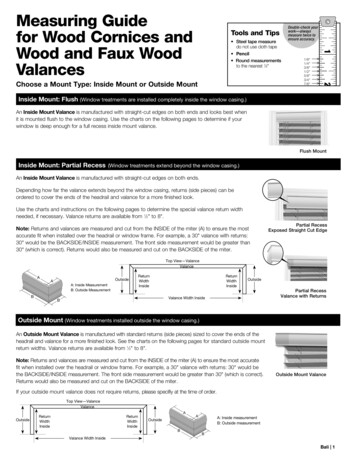
INTRODUCTION TO MACHINING2.3Linear measuring tools:2.3.1 Steel rule:Steel rules are very useful for making quick measurements with up to 1/32" or 0.5 [mm]accuracy. They have typical discriminations of 1/16", 1/32", 1/64" or 1/100" for inchbased rules and 0.5 [mm] for metric rules and are available in varying lengths.Measurements of 1/64" or 1/100" require practice and are not very reliable; for this kindof accuracy other instruments should be used.The rule shown in Figure 2.1, front and back, hasdiscriminations of 1/8", 1/16", 1/32" and 1/64".Many other discrimination combinations areavailable, such as inch units on one side and mmon the other side.Since steel rules have a thickness, it is essentialthat, whenever using a steel rule, the line of sightFigure 2.3.1: Front and Back of a Machinist’s Rulemust be perpendicular to the face of the rule,otherwise a reading error (parallax error) will be incurred.52
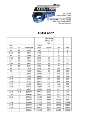
INTRODUCTION TO MACHINING2.3.2 Vernier calipers:Vernier calipers are actually “improved” rules: they use 2 jaws to “identify” the lineardistance and an improved scale, the Vernier scale, to arrive at a more precisemeasurement.Figure 2.3.2: Metric Vernier CaliperFigure 2.3.3: Dual Unit Vernier CaliperFigure 2.3.4: Components of a Vernier Caliper53
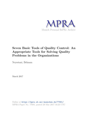
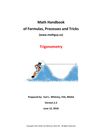
INTRODUCTION TO MACHININGReading Vernier scales:Figure 2.3.5: Reading Vernier ScalesStep 1:On the main scale find the value “below” the zero of the Vernier scale. Inthe image above, that would be 3 [mm]. Make sure that you know what thegraduations on the main scale represent.Step 2:Determine the graduation line on the Vernier scale, which coincides with agraduation line on the main scale; depending on the quality of youreyesight, this could be the line at the “6" of the Vernier scale or the nextline. If it is the “6" line, then the measurement would be:3 [mm] 0.60 [mm] 3.60 [mm] (NOT 3.6 [mm])If it is the line following the “6" on the Vernier scale, then the measurementwould be:3 [mm] 0.62 [mm] 3.62 [mm]Make sure you are aware of the value of each increment on the Vernierscale, for this case: 0.02 [mm].54
INTRODUCTION TO MACHININGExample 1:This appears to be the Vernier scale onan angle measuring tool; therefore thebase units on the main scale will bedegrees, on the Vernier scale 0.1degrees.Step 1:the zero of the Vernier scaleis at 19 degrees.Step 2:the first alignment is at 0.8degrees.Answer:the angle is 19.8 degrees.Figure 2.3.6: Angular Vernier ScaleExample 2:Figure 2.3.7: Dual Vernier ScalesFind both, the inch and the metric value shown in the figure above.Inch scale:again, make sure that you know what the increments on both scalesare.Step 1:the zero of the Vernier scale is at: 0.95" on themain scale.Step 2:the first alignment is 3 lines past the “15" on theVernier scale: 0.018"Answer:0.968"Metric scale:Step 1:24 [mm]Step 2:0.62 [mm]Answer:24.62 [mm]55
INTRODUCTION TO MACHININGMeasuring procedure:-Ensure that the jaws of the caliper are clean: close the jaws, hold them against alight source: there must not be any gap between the jaws. At that point check thatthe instrument reads zero.-Whenever possible use the knife edge part of the jaws for your measurements,especially when the two measurement surfaces are not parallel.-If at all possible, read the caliper while still on the work-piece; else use thelocking screw.-Attempt to exert the same jaw pressure for all measurements.2.3.3 Dial calipers:Instead of using a Vernier scale, these calipers use a dial indicator for the higherdiscrimination aspect of the instrument; otherwise they are no different from Verniercalipers. Since there is a “gap” between the rotating hand and the dial face, the line ofsight, when reading the instrument, must be perpendicular to the face of the dial or elsea reading error will occur.Figure 2.3.8: Dial Caliper56
INTRODUCTION TO MACHINING2.3.4 Digital calipers:A digital read-out replaces all scales. It is important to zero the calipers before takingmeasurements and select the appropriate units (metric or imperial).Figure 2.3.9: Digital CaliperIf the caliper appears to be well used or even “abused”, ensure that the instrument is stillcalibrated: take something of known dimension and verify it using the caliper.57
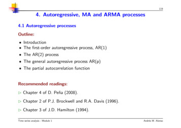
INTRODUCTION TO MACHINING2.3.5 Outside micrometers:Standard micrometers have a discrimination of 0.001" or 0.01 [mm], those with a Vernierscale have discriminations of one magnitude higher. Digital micrometers may have adiscrimination as fine as 0.00005". Their only limitation is the limited range: they typicallyare only capable of measuring over a range of 1" (or 25 mm). This means in order tomake measurements of 20 mm and 40 mm, two different micrometers would have tobe used.The spindle should onlybe moved using theratchet stop and not thethimble to prevent anydamage to the hardenedspindle and anvil facesdue to excessivepressure. The ratchetstop contains a slipclutch which will begin toslip at the properFigure 2.3.10: Outside Inch Vernier Micrometerpressure, thus alsoensuring constant measurement pressure. The thimble can be used when opening theinstrument.Figure 2.3.11 shows a set ofmicrometers, capable of measuring:-from 0" to 1"-from 1" to 2"-from 2" to 3" and-from 3" to 4".Note that each instrument has arange of 1" only.Metric micrometer sets are availablein increments of 25 mm.Figure 2.3.11: Micrometer Set 1" to 4"58
INTRODUCTION TO MACHININGMicrometers with a discrimination of 0.001", 0.02 [mm] or 0.01 [mm] have the main scalealong the sleeve and the secondary scale around the thimble. Instruments with adiscrimination of 0.0001" or 0.001 [mm] have an additional Vernier scale around parts ofthe sleeve.A description of micrometers and how to read them can be found 2 p1 5.pdfNote:before using any analogue instruments be aware of thediscrimination of each one of the scales and ensure that, when thejaws closed, the instrument reads zero.Example 1:Shown in the figures below is part of an inch Verniermicrometer. What is the measured dimension?Figure 2.3.12: Main ScaleFigure 2.3.13: Vernier ScaleOn the main scale on the sleeve the reading would be 0.250", on the thimblescale the reading is 0.000" and on the Vernier scale the first matching lines are at0.0007".Answer:0.250" 0.000" 0.0007" 0.2507"59
INTRODUCTION TO MACHININGExample 2:Ignoring the barely visible Vernier scale on this metric micrometer,determine the measured dimension.The increments on the main scale arein 0.5 [mm], and therefore we arrive at5.5 [mm].On the thimble scale we get a readingof 0.28 [mm].Answer:5.5 [mm] 0.28 [mm] 5.78 [mm]Figure 2.3.14: Metric Micrometer ScalesOutside micrometers are also available with digital read-outs.Figure 2.3.15: Digital Outside MicrometerOther types of micrometers are the inside micrometer and the depth micrometer. Beaware that the depth micrometer has a “backwards” sleeve scale.60
INTRODUCTION TO MACHINING2.4Comparison Instruments:Sometimes these instruments are referred to as Transfer Instruments: the tool itself isnot capable of producing a measurement, but is used to “simulate” the dimension whichneeds to be measured. A suitable tool (Vernier Caliper, Micrometer etc.) is thenused to determine the actual dimension.Many instruments fall into this category: simple calipers, telescoping gauges, small holegauges, thickness gauges, dial indicators and optical comparators.2.4.1 Transfer calipers:Transfer calipers are convenient tools whentaking measurements of parts which are stillmounted in a machine and where it is difficultor impossible to use an actual measuringtool. The process is quite simple: lock thejaws of the caliper in the correct position andthen use a conventional instrument to obtainan actual measurement. Their accuracy issomewhat limited.61Figure 2.4.1: Transfer Calipers
INTRODUCTION TO MACHINING2.4.2 Telescoping gauges:Figure 2.4.2: Telescoping GaugesFigure 2.4.3: Telescoping Gauge and Vernier CaliperOne or both ends of the telescoping gauge can be pushed inward, the gauge is theninserted into the hole, then the locking nut is used to fix the gauge ends in their positionand the instrument is removed from the hole. A standard measuring tool is then used todetermine the dimension.62
INTRODUCTION TO MACHINING2.4.3 Dial indicators:Dial indicators show the deviation of a dimension from a “true” dimension.The dial indicator consists of a plunger whichcan move up or down moving the dial hand ineither a clockwise or counter-clockwisedirection. The smaller dial indicates thenumber of full revolutions of the large hand.Dial indicators have a limited range of travel(the one in Figure 2.2.18 has a travel of 0 - 3mm), and a discrimination of 0.01 mm ortypically 0.001" for inch based dial indicators.Ensure that the plunger axis is alwaysperpendicular to the surface which is beingevaluated otherwise a measurement error willbe incurred.Figure 2.4.4: Dial Indicator63
INTRODUCTION TO MACHININGSetting up a dial indicator:Figure 2.2.19 shows a dial indicatormounted on a typical stand which in turn isplaced on a rigid surface. A reference(master) specimen of exactly known heightis then placed under the plunger and thebezel is rotated so that the instrument readsexactly zero; ensure that the plunger canstill travel in both directions and is not“bottomed out” in one direction. Theinstrument is now set up to compare aFigure 2.4.5: Dial Indicator and Standspecimen to the “calibrated” height. The instrument will indicate the deviation of thatdimension from the “calibrated” standard.Two main sources of error:The plunger axis is not perpendicular to the surface of the specimen being measured(cosine error) and the line of sight is not perpendicular to the dial face (parallax error).As always: ensure that the plunger tip and the surface to be measured are clean.Dial indicators are also available in digital form.64
INTRODUCTION TO MACHINING2.4.4 Dial test indicator:This instrument is used for the same type of measurements as the dial indicator, but hasa finer discrimination: typically 0.0005" to 0.0001" or 0.002 mm to 0.001 mm.Dial test indicators are used exactly the sameway as dial indicators.Because of the pivoting probe, there is thepotential for another type of error: the arc versuscord-length error.To avoid this error, don’t use this instrumentwhen larger variations in the measurement canbe expected.Figure 2.4.6: Dial Test Indicator65
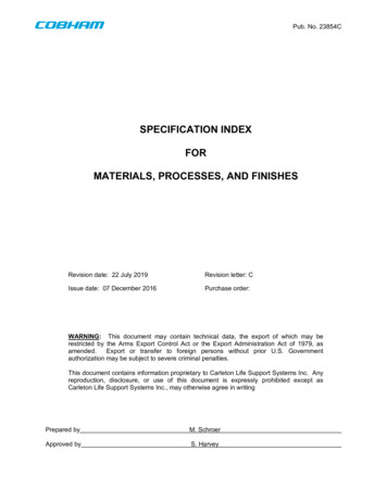
INTRODUCTION TO MACHINING2.4.5 Gauge blocks:Gauge blocks are a set of precise reference blocks which are used to establish aspecified (reference) height. They come in stets of standard sizes and need to be“wrung” together for the correct overall dimension. The process of “wringing” ensuresthat there is no cumulative error due to the build up of air-films between the gaugeblocks.Gauge blocks must be cleaned before AND after use.Figure 2.4.7: Gauge Block SetFigure 24.8: Wrung Gauge Blocks66
Reading Vernier scales: Step 1: On the main scale find the value “below” the zero of the Vernier scale. In the image above, that would be 3 [mm]. Make sure that you know what the graduations on the main scale represent. Step 2: Determine the graduation line on the Vernier scale, which coincides with a graduation line on the main scale; depending on the quality of your eyesight, this could .