Transcription
Owner’s Manual & Safety InstructionsSave This Manual Keep this manual for the safety warnings and precautions, assembly,operating, inspection, maintenance and cleaning procedures. Write the product’s serial number in theback of the manual near the assembly diagram (or month and year of purchase if product has no number).Keep this manual and the receipt in a safe and dry place for future reference. CHARGE COMPLETELYIMMEDIATELY AFTERPURCHASE.Fully recharge aftereach jump-start.Fully recharge monthly toensure long battery life.Visit our website at: http://www.harborfreight.comEmail our technical support at: productsupport@harborfreight.comWhen unpacking, make sure that the product is intactand undamaged. If any parts are missing or broken,please call 1-888-866-5797 as soon as possible.Copyright 2019 by Harbor Freight Tools . All rights reserved.No portion of this manual or any artwork contained herein may be reproduced inany shape or form without the express written consent of Harbor Freight Tools.Diagrams within this manual may not be drawn proportionally. Due to continuingimprovements, actual product may differ slightly from the product described herein.Tools required for assembly and service may not be included.Read this material before using this product.Failure to do so can result in serious injury.SAVE THIS MANUAL.19l
Table of ContentsSAFETYSafety . 2Specifications . 4Setup . 5Operation . 8Maintenance . 10Parts List and Diagram . 11Warranty . 12 WARnInG SYMBOLS AnD DEFInITIOnSThis is the safety alert symbol. It is used to alert you to potential personal injury hazards.Obey all safety messages that follow this symbol to avoid possible injury or death.SETUPIndicates a hazardous situation which, if not avoided,will result in death or serious injury.Indicates a hazardous situation which, if not avoided,could result in death or serious injury.Indicates a hazardous situation which, if not avoided,could result in minor or moderate injury.Addresses practices not related to personal injury.OPERATIOnMAInTEnAnCEV ACCARCAhPage 2VoltsAlternating CurrentWARNING markingconcerning Risk of Eye Injury.Wear ANSI-approvedsplash-resistant safety goggles.Read the manual beforeset-up and/or use.AmperesCold Cranking AmpsReserve CapacityWARNING markingconcerning Risk of Fire.Follow connection procedure.Ampere-hoursFor technical questions, please call 1-888-866-5797.Item 56631
Safety Warnings and PrecautionsSAFETYGeneral Safety WarningsRead all safety warnings and instructions.Failure to follow the warnings and instructions may result in electric shock, fire and/or serious injury.Save all warnings and instructions for future reference.WARnInG – RISK OF EXPLOSIVE GASES.Working in vicinity of a lead-acid battery isdangerous. Batteries generate explosive gasesduring normal battery operation. For this reason,it is of utmost importance that you follow theinstructions each time you use the Power Pack.To reduce risk of battery explosion, follow theseinstructions and those published by batterymanufacturer and manufacturer of any equipment youintend to use in vicinity of battery. Review cautionarymarking on these products and on engine.Work Area Safety2. Do not operate Power Pack in explosiveatmospheres, such as in the presenceof flammable liquids, gases or dust.The Power Pack can create sparkswhich may ignite the dust or fumes.3. Keep children and bystanders awaywhile operating the Power Pack.Distractions can cause you to lose control.SETUP1. Keep work area clean and well lit.Cluttered or dark areas invite accidents.4. Store idle equipment. Always lock uptools and keep out of reach of children.1. Do not drop a metal tool onto battery. Itmight spark or short-circuit battery or otherelectrical part that may cause explosion.4. Do not expose to rain or wet conditions.Water entering the Power Pack willincrease the risk of electric shock.2. Do not operate if Power Pack hasreceived a sharp blow, been dropped,or otherwise damaged in any way;take it to a qualified technician.5. Do not use an extension cord with this item.3. Do not leave Power Pack unattendedwhile switched on. It could resultin fire and property damage.6. Use of an attachment not recommended orsold by the manufacturer may result in a riskof fire, electric shock, or injury to persons.7. To reduce risk of damage to electric plugand cord, pull by plug rather than cordwhen disconnecting the Adapter.OPERATIOnElectrical Safety8. Do not operate with damaged cord or plug.Replace the cord or plug immediately.Personal SafetyWear AnSI-approved splashresistant safety goggles and heavyduty rubber work gloves wheneverconnecting, disconnecting, orworking near battery. Battery acidcan cause permanent blindness.Avoid touching eyes while working near battery.2. Do not use Power Pack while you are tiredor under the influence of drugs, alcoholor medication. A moment of inattentionwhile operating Power Pack mayresult in serious personal injury.Item 566313. nEVER smoke or allow a spark or flamein vicinity of battery or engine.4. If battery acid contacts skin or clothing,wash immediately with soap and water.If acid enters eye, immediately flood eye withrunning cold water for at least 10 minutesand get medical attention immediately.5. Remove personal metal items such as rings,bracelets, necklaces, and watches when workingwith a lead-acid battery. A lead-acid battery canproduce a short-circuit current high enough to welda ring or the like to metal, causing a severe burn.For technical questions, please call 1-888-866-5797.Page 3MAInTEnAnCE1.
6. People with pacemakers should consult theirphysician(s) before use. Electromagnetic fields inclose proximity to heart pacemaker could causepacemaker interference or pacemaker failure.ServiceSAFETYHave your Power Pack serviced by a qualified repair person using only identical replacement parts.This will ensure that the safety of the Power Pack is maintained.Power Pack Safety Warnings1. Lead-acid batteries generate hydrogen gas whencharging. Hydrogen gas is explosive. Only usethe Jump-Start system in a well-ventilated area.i. Connect and disconnect battery cableclamps only after setting any Jump Starterswitches to OFF position.2. Jump Starting A Vehiclej. Connect cables to proper polarities. Connectblack cable to negative body ground andred cable to positive battery terminal.a. Use the Power Pack for jump startinga LEAD-ACID battery only.SETUPb. For emergency use only. Do not use the PowerPack as a replacement for a vehicle battery.c. Be sure area around battery is well ventilatedwhile battery is being jump started.d. NEVER jump start a frozen battery.e. Do not attempt to jump start a vehicle witha non-rechargeable or defective battery.f. Study all battery manufacturer’s specificprecautions for jump starting.g. DO nOT TOUCH POSITIVE AnD nEGATIVEBATTERY CLAMPS TOGETHER.h. Unplug the Power Pack from its Adapterbefore connecting its cables to a battery.k. Locate Power Pack as far away frombattery as battery cables permit.3. Maintain labels and nameplates on the Power Pack.These carry important safety information.If unreadable or missing, contactHarbor Freight Tools for a replacement.4. The warnings, precautions, and instructionsdiscussed in this instruction manual cannotcover all possible conditions and situationsthat may occur. It must be understood by theoperator that common sense and caution arefactors which cannot be built into this product,but must be supplied by the operator.OPERATIOnSAVE THESE InSTRUCTIOnS.SpecificationsCranking Amps330Battery12 VDC, 17AhBattery Cables42″ LMaximum Air Pressure250 PSIFunctions: 12 Volt Jump-Starter, Air Compressor,12 VDC Power Supply, and 3 LED Work LightMAInTEnAnCEPage 4For technical questions, please call 1-888-866-5797.Item 56631
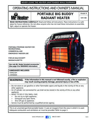
Setup - Before Use:Read the EnTIRE IMPORTAnT SAFETY InSTRUCTIOnS section at the beginning of thismanual including all text under subheadings therein before setup or use of this product.SAFETYnote: For additional information regarding the parts listed in thefollowing pages, refer to Parts List and Diagram on page 11.FunctionsClamp PowerSwitchWorkLightConnectionIndicator yCableSETUPChargeIndicatorLightsUSB PortBattery TestButton /USB PowerButton120VACChargingInput Plug(on back)OPERATIOnWork LightButtonAir CompressorSwitchMAInTEnAnCEAirPressureGaugeAir HoseCompartmentFigure AItem 56631For technical questions, please call 1-888-866-5797.Page 5
Charging the Power PackWARnInG! Always charge on a non-flammable surface.ApproximateAC Charge TimePress and hold the Battery Test Button on the frontof the unit to check the battery power level.SAFETYInitial Charge:48 hoursRecharge:30 hoursa. Green light is ready for use.b. Yellow light needs to be charged.c. Red light should be charged immediately.Figure B1. Plug the 120VAC Adapter into a 2 or 3-prong outlet.3. The Charging Indicator lights will illuminate in acycle from red, to yellow, to green while the unitis charging. The green Charging Indicator lightwill remain on after charging is complete.The battery power level must be checkedperiodically when charging, and the Power Packmust be unplugged when it is fully charged.2. Slide the Adapter socket on the 120VACCharging Input on the back of the Power Pack.nOTE: FAILURE TO RECHARGE POWERPACK WILL VOID WARRAnTY.Turn the Clamp Power Switch on frontof unit to the OFF position.note: Before initial use, completelycharge the Power Pack.SETUP4. Recharge:a. When yellow light comes on whilepressing the Battery Test Button.b. After each Jump-Start.c. Once a month.DO nOT EXCEED MAXIMUM CHARGInG TIMEOPERATIOnMAInTEnAnCEPage 6For technical questions, please call 1-888-866-5797.Item 56631
DC Appliance CompatibilityCalculate the total wattage needed to run theappliance before operation. You do not needto calculate startup or surge wattages.To calculate the size of the load you plan to usewith the Power Pack, use the following formula:Amps x Volts WattsFor example, if you use an appliance whoserunning amps total 7 amps, you will need 84watts of power (7 amps x 12V 84 Watts) torun the items. This figure is within the capacityof the unit (10 amps x 12V 120 Watts).The actual power usage may vary based on themodel or brand of the appliance. Check the actualwattage of your appliances and calculate theamount of power needed to run/charge them.ApplianceEstimatedPower(watts)EstimatedUse (hours)4509261514248488032Fluorescent Light,Cell Phone ChargerRadio, Fan,Depth FinderVideo Recorder/Player, SpotlightSmall Power Tool,Bilge PumpElectric CoolerAir CompressorSAFETYThe lower the amount of watts the appliancedraws, the longer the Power Pack can powerit before needing to be recharged.note: Use this chart as a guideline only.SETUPThe Power Pack can run/charge 12VDCauto, RV, marine, or other portableappliances that draw 10 amps or less.MAInTEnAnCEOPERATIOnFigure CItem 56631For technical questions, please call 1-888-866-5797.Page 7
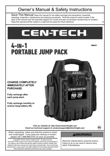
Operating InstructionsUsing the Work LightSAFETY1. To turn the Work Light on, pressthe Work Light button.3. To turn the Work Light off, pressthe Work Light button again.2. To turn flashing lights on, press theWork Light button again.Jump Starting a Vehiclenote: Read the vehicle owner’s manual pertainingto jump starting prior to using the Power Pack.WARnInG! DO nOT COnnECT TO THEnEGATIVE TERMInAL OF THE BATTERY.1. Press the Battery Test button to verify that thePower Pack is fully charged. Recharge asneeded, following the instructions in the “Chargingthe Power Pack” section on page 6.4. When the correct connection has been made, turnthe Clamp Power Switch to the ON position.SETUP2. Turn off the vehicle ignition switch and allaccessories (lights, radio, climate control, etc.).3. Turn Clamp Power Switch on the PowerPack to their OFF position. You mayleave the Work Light on if needed.WARnInG! DO nOT TOUCH POSITIVE AnDnEGATIVE BATTERY CLAMPS TOGETHER.5. WAIT FIVE MInUTES, then start thevehicle. If the vehicle does not start, wait anadditional 3 minutes before trying again.WARnInG! THE VEHICLE WILL nOT START IFYOU DO nOT WAIT AT LEAST 5 MInUTES.6. After the vehicle is started, turn the ClampPower Switch to the OFF position. Removethe black Negative Battery Cable first, andthen the red Positive Battery Cable.3. Connect the red Positive Battery Cable tovehicle’s positive battery terminal. Connectthe black Negative Battery Cable to a nonmoving metal part of the vehicle.OPERATIOnUsing the Air CompressorTire Inflator1. Press the Battery Test button to verify that thePower Pack is fully charged. Recharge as needed,following the instructions in the “Chargingthe Power Pack” section on page 6.2. Open the Air Hose Compartment on theback of the unit and pull out the air hose.3. Check the proper inflation level for the object that isbeing inflated.AdapterinstalledLeverpresseddownAir HoseTire InflationMAInTEnAnCE1. Position the Tire Inflator over the valve stem andpush down firmly, making sure it is fully seated.2. Press the lever down. (See Figure D.)Figure D3. Press the Air Compressor Switch on.note: Monitor the Air Pressure Gauge on thefront of the unit to avoid over-inflation.4. When the proper inflation level has beenreached, press the Air Compressor Switch off.5. Lift the lever and remove the hose.Page 8For technical questions, please call 1-888-866-5797.Item 56631
Using Hose Adapters1. Three adapters are included with thePower Pack that can be attached tothe Tire Inflator. (See Figure E.)2. Attach the proper adapter to the TireInflator for the object to be inflated.3. Insert the adapter into the object’sreceptacle and press the lever down.note: Monitor the Air Pressure Gauge on thefront of the unit to avoid over-inflation.5. When the proper inflation level has beenreached, press the Air Compressor Switch off.SAFETY4. Press the Air Compressor Switch on.6. Lift the lever and remove the hose.WARnInG! Do not overinflate any object.SETUPFigure ERunning/Charging DC Appliances1. Press the Battery Test Button to verify that thePower Pack is fully charged. Recharge asneeded, following the instructions in the “Chargingthe Power Pack” section on page 6.3. Make sure that the Clamp PowerSwitch and appliance are off.2. Make sure the total wattage of the appliance iswithin the range of the Power Pack. See “DCAppliance Compatibility” on page 7.5. Turn on the appliance.4. Plug the appliance into the 12VDC Outlet.6. When finished using, turn off andunplug the appliance.2. Plug the device into the USB Port.3. When finished, unplug the device from the USB Port.MAInTEnAnCE1. Press the Battery Test button to verify thatthe Power Pack is fully charged. Rechargeas needed, following the instructions in the“Charging the Power Pack” section on page 6.Record Product’s Serial number Here:note: If product has no serial number, record month and year of purchase instead.note: Some parts are listed and shown for illustration purposes only, and are not available individuallyas replacement parts. Internal parts are not user-serviceable and are not available.Item 56631For technical questions, please call 1-888-866-5797.OPERATIOnRunning/Charging USB DevicesPage 9
Maintenance and ServicingProcedures not specifically explained in this manual mustbe performed only by a qualified technician.SAFETYTO PREVEnT SERIOUS InJURY: Unplug the Power Pack, turn the Clamp Power Switch off and allowPower Pack to cool completely before performing any inspection, maintenance, or cleaning procedures.1. BEFORE EACH USE, inspect the generalcondition of the Power Pack. Check for: loose hardware, cracked or broken parts, damaged electrical wiring or cable insulation, and any other condition that mayaffect its safe operation.3. For longer working life, protect PowerPack from sunlight and moisture.4. AFTER USE, wipe external surfaces ofthe Power Pack with clean cloth.5. COnTAInS nOn-SPILLABLE, SEALEDLEAD-ACID BATTERY. BATTERYMUST BE RECYCLED.SETUP2. Keep unit clean and clamps freeof dirt, debris, or grease.Battery Replacement and DisposalLEAD BATTERY MUST BE RECYCLED.WARnInG! To prevent damage or injury, replacement battery must be identical to original.OPERATIOnReplace the Battery when the red light comes on whilepressing the Battery Test button after recharging.3. Detach the recharging wires and BatteryCables from the battery terminals.1. Remove all screws from the back ofthe case and lift off the panel.4. Position the replacement battery with the labelfacing out, and make sure the red ( ) rechargingwire and Battery Cable is attached to thepositive ( ) battery terminal. Connect both ofthe recharging wires and Battery Cables.2. Lift out the Battery withoutdamaging the circuit board.note: Notice how the red and black cables connectto the old battery and make sure to keep themin place, connecting them to the new battery.5. Carefully slide the Battery into the compartmentwithout damaging the circuit board.6. Replace the back panel and the screws.MAInTEnAnCEPLEASE READ THE FOLLOWInG CAREFULLYTHE MANUFACTURER AND/OR DISTRIBUTOR HAS PROVIDED THE PARTS LIST AND ASSEMBLY DIAGRAMIN THIS MANUAL AS A REFERENCE TOOL ONLY. NEITHER THE MANUFACTURER OR DISTRIBUTORMAKES ANY REPRESENTATION OR WARRANTY OF ANY KIND TO THE BUYER THAT HE OR SHE ISQUALIFIED TO MAKE ANY REPAIRS TO THE PRODUCT, OR THAT HE OR SHE IS QUALIFIED TO REPLACEANY PARTS OF THE PRODUCT. IN FACT, THE MANUFACTURER AND/OR DISTRIBUTOR EXPRESSLYSTATES THAT ALL REPAIRS AND PARTS REPLACEMENTS SHOULD BE UNDERTAKEN BY CERTIFIED ANDLICENSED TECHNICIANS, AND NOT BY THE BUYER. THE BUYER ASSUMES ALL RISK AND LIABILITYARISING OUT OF HIS OR HER REPAIRS TO THE ORIGINAL PRODUCT OR REPLACEMENT PARTSTHERETO, OR ARISING OUT OF HIS OR HER INSTALLATION OF REPLACEMENT PARTS THERETO.Page 10For technical questions, please call 1-888-866-5797.Item 56631
Parts List and 81920212223242526111272829DescriptionLower Air Compressor Switch CoverAir Compressor SwitchCompressor Meter FixtureCompressor HoopInternal Adaptor (120 VAC)Adaptor StatorCompressorNegative Battery Cable (Black)Positive 12 VDC OutletMain Circuit BoardUSB CapFront CaseInternal Connection WireAC Power escription12 VDC Outlet CoverPower Switch CapNegative 12 VDC OutletPower SwitchPositive 12 VDC OutletMiddle CaseLensLED BoardBatteryLED Lamp PanelPositive Battery Cable (Red)HandleBack CaseAir Hose CompartmentUpper Air Compressor Switch CoverSAFETYPartItem 56631For technical questions, please call 1-888-866-5797.Page 11
Limited 90 Day WarrantyHarbor Freight Tools Co. makes every effort to assure that its products meet high quality and durability standards,and warrants to the original purchaser that this product is free from defects in materials and workmanship for theperiod of 90 days from the date of purchase. This warranty does not apply to damage due directly or indirectly,to misuse, abuse, negligence or accidents, repairs or alterations outside our facilities, criminal activity, improperinstallation, normal wear and tear, or to lack of maintenance. We shall in no event be liable for death, injuriesto persons or property, or for incidental, contingent, special or consequential damages arising from the use ofour product. Some states do not allow the exclusion or limitation of incidental or consequential damages, so theabove limitation of exclusion may not apply to you. THIS WARRANTY IS EXPRESSLY IN LIEU OF ALL OTHERWARRANTIES, EXPRESS OR IMPLIED, INCLUDING THE WARRANTIES OF MERCHANTABILITY AND FITNESS.To take advantage of this warranty, the product or part must be returned to us with transportation chargesprepaid. Proof of purchase date and an explanation of the complaint must accompany the merchandise.If our inspection verifies the defect, we will either repair or replace the product at our election or we mayelect to refund the purchase price if we cannot readily and quickly provide you with a replacement. We willreturn repaired products at our expense, but if we determine there is no defect, or that the defect resultedfrom causes not within the scope of our warranty, then you must bear the cost of returning the product.This warranty gives you specific legal rights and you may also have other rights which vary from state to state. 26541 Agoura Road Calabasas, CA 91302 1-888-866-5797
Owner’s Manual & Safety Instructions Save This Manual Keep this manual for the safety warnings and precautions, assembly, operating, inspection, maintenance and cleaning procedures. Write the product’s serial number in the back of the manual near the assembly diagram