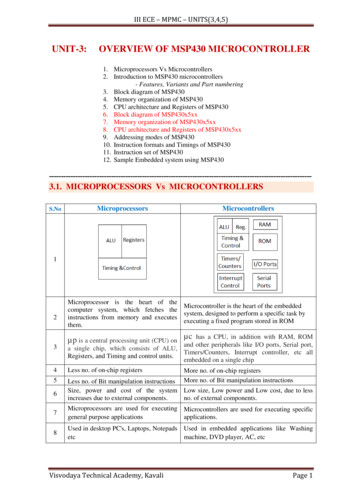
Transcription
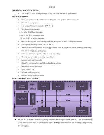
CPE 323 MSP430 INSTRUCTION SET ARCHITECTUREAleksandar MilenkovicThe MSP430 is a 16-bit, byte-addressable, RISC-like architecture. The maincharacteristics of the instruction set architecture are as follows.RegistersThe MSP430 has a register file with 16 registers (R0-R15) that are all visible toprogrammers. Register R0 is reserved for the program counter (PC), register R1 servesas the stack pointer, and register R2 serves as the status register. Register R3 can be usedfor constant generation, while the remaining registers R4-R15 serve as general-purposeregisters.A relatively large number of general-purpose registers compared to othermicrocontrollers, allows the majority of program computation to take place on operandsin general-purpose registers, rather than operands in main memory. This helps improveperformance and reduce code size.A block diagram of the processor core is shown in Figure 1. Register-register operationsare performed in a single clock cycle.
Figure 1. MSP430 CPU Block Diagram.Program counter (PC/R0). PC always points to the next instruction to be executed.MS430 instructions can be encoded with 2 bytes, 4 bytes, or 6 bytes depending onaddressing modes used for source (src) and source/destination (src/dest) operands. Hence,the instructions have always an even number of bytes (they are word-aligned), so theleast significant bit of the PC is always zero.The PC can be addressed by all instructions. Let us consider several examples:MOV #LABEL,PC ; Branch to address LABELMOV LABEL,PC ; Branch to address contained in LABELMOV @R14,PC ; Branch indirect to address in R14Stack pointer (SP/R1). The program stack is a dynamic LIFO (Last-In-First-Out)structure allocated in RAM memory. The stack is used to store the return addresses ofsubroutine calls and interrupts, as well as the storage for local data and passingparameters. The MSP430 architecture assumes the following stack convention: the SPpoints to the last full location on the top of the stack, and the stack grows toward loweraddresses in memory. The stack is also word-aligned, so the LSB bit of the SP is always0.Two main stack operations are PUSH (the SP is first decremented by 2, and then theoperand is stored in memory at the location addressed by the SP), and POP (the contentfrom the top of the stack is retrieved; the SP is incremented by 2).
[[Illustrate PUSH and POP operations on the stack.]]Status register (SR/R2). The status register keeps the content of arithmetic flags (C, V, N,Z), as well as some control bits such as SCG1, SCG0, OSCOFF, CPUOFF, and GIE.The exact format of the status register and the meaning of the individual bits is show inFigure 2.Figure 2. Status register format (top) and bits description (bottom).Constant generator (R2-R3). Profiling common programs for constants shows that just afew constants, such as 0, 1, 2, 4, 8, -1, are responsible for majority of programconstants. However, to encode such a constant we will need 16 bits in our instruction. Inorder to reduce the number of bits spent for encoding frequently used constants, a trickcalled constant generation is used. By specifying dedicated registers R2 and R3 incombination with certain addressing modes, we tell hardware to generate certainconstants. This results in shorter instructions (we need less bits to encode such aninstruction). Error! Reference source not found. describes values of constantgenerators.
Figure 3. Constant generation.An example: Let’s say you want to clear a word in memory at the address dst. To do this,a MOVE instruction could be used:MOVE #0, dstThis instruction would have 3 words: the first contains the opcode and addressing modespecifiers. The second word keeps the constant zero, and the third word contains theaddress of the memory location. Alternatively, the instructionMOVE R3, dstperforms the same task, but we need only 2 words to encode it.General-purpose registers (R4-R15). These registers can be used to store temporary datavalues, addresses of memory locations, or index values, and can be accessed with BYTEor WORD instructions.Let us consider a register-byte operation using the following instruction:ADD.BR5, 0(R6)This instruction specifies that a source operand is the register R5, and src/dest operand isin memory at the address (R6 0). The suffix .B indicates that the operation should beperformed on byte-size operands. Thus, a lower byte from the register R5, 0x8F, isadded to the byte from the memory location Mem(0x0203) 0x12, and the result iswritten back, so the new value of Mem(0x0203) 0xA1. The content of the register R5 isintact.Let us now consider a byte-register operation using the following instruction:ADD.B @R6, R5.This instruction specifies a source operand in memory at the address contained in R6, andthe destination operand is in the register R5. A suffix .B is used to indicate that theoperation uses byte-sized operands. A suffix .W indicates that operations are performedon word-sized operands and is default (i.e., by omitting .W we imply word-sizedoperands). As shown below, a byte value Mem(0x0223) 0x5F is added to the lower byteof R5, 0x02. The result of 0x61 is zero extended to whole word, and the result is writtenback to register R6. So, the upper byte is always cleared in case of byte-registeroperations.
Figure 4. Register-byte (left) and byte-register (right) operations.Addressing ModesThe MSP430 architecture supports a relatively rich set of addressing modes. Seven ofaddressing modes can be used to specify a source operand in any location in memory(Figure 5), and the first four of these can be used to specify the source/destinationoperand. Figure 5 also illustrates the syntax and give a short description of the addressingmodes. The addressing modes are encoded using As and Ad address specifiers in theinstruction word, and the first column shows how they are encoded.Figure 5. Addressing Modes.
Register mode. The fastest and shortest mode is used to specify operands in registers.The address field specifies the register number (4 bits).Indexed mode. The operand is located in memory and its address is calculated as a sumof the specified address register and the displacement X, which is specified in the nextinstruction word. The effective address of the operand is ea, ea Rn X.Symbolic mode. This addressing mode can be considered as a subset of the indexedmode. The only difference is that the address register is the PC, and thus ea PC X.Absolute mode. The instruction specifies the absolute (or direct) address of the operandin memory. The instruction includes a word that specifies this address.Indirect register mode. It can be used only for source operands, and the instructionspecifies the address register Rn, and the ea Rn.Indirect autoincrement. The effective address is the content of the specified addressregister Rn, but the content of the register is incremented afterwards by 1 for byte-sizeoperations and by 2 for word-size operations.Immediate mode. The instruction specifies the immediate constant that is operand, and isencoded directly in the instruction.One should notice a smart encoding of the addressing modes. Only a 2-bit addressspecifier As is sufficient in encoding 7 addressing modes. How does it work? Forexample, please note that the absolute addressing mode is encoded in the same way as theindexed and the symbolic modes, As 01. However, the absolute mode specifies the SRregister as the address register. It is never used in the indexed mode as an addressregister, so this combination indicates the absolute addressing. Next, the immediatemode uses the same As 11 as the autoincrement mode. It is distinguished from theautoincrement mode because the specified register is the PC, which is never used in theautoincrement mode. Similarly, we can explain how only a single bit Ad suffices indistinguishing 4 addressing modes for the destination operand.[[Examples]]Instruction SetThe MSP430 instruction set consists of 27 core instructions and 24 emulated instructions.The core instructions are instructions that have unique op-codes decoded by the CPU.The emulated instructions are instructions that make code easier to write and read, but donot have op-codes themselves, instead they are replaced automatically by the assemblerwith an equivalent core instruction. There is no code or performance penalty for usingemulated instruction.There are three core-instruction formats:
Double-operandSingle-operandJumpAll single-operand and double-operand instructions can be byte or word instructions byusing .B or .W extensions. Byte instructions are used to access byte data or byteperipherals. Word instructions are used to access word data or word peripherals. If noextension is used, the instruction is a word instruction.The source and destination of an instruction are defined by the following fields: src - The source operand defined by As and S-rego As - The addressing bits responsible for the addressing mode used for thesource (src)o S-reg The working register used for the source (src) dst - The destination operand defined by Ad and D-rego Ad - The addressing bits responsible for the addressing mode used for thedestination (dst)o D-reg - The working register used for the destination (dst) B/W Byte or word operation:o 0: word operationo 1: byte operationFigure 6 shows the double-operand instruction format and the list of all double-operandcore instructions.Figure 6. Double-operand instruction format (top) and instruction table (bottom).Figure 7shows the single-operand instruction format and the list of all single-operandcore instructions.
Figure 7. Single-operand instruction format (top) and instruction table (bottom).Figure 7shows the jump instruction format and the list of all jump core instructions.Conditional jumps support program branching relative to the PC and do not affect thestatus bits. The possible jump range is from 511 to 512 words relative to the PC valueat the jump instruction. The 10-bit program-counter offset is treated as a signed 10-bitvalue that is doubled and added to the program counter:PCnew PCold 2 PCoffset 2Figure 8. Jump instruction format (top) and instruction table (bottom).Figure 9 shows a complete list of the MSP430 core and emulated instructions.
Figure 9. The complete MSP430 Instruction Set (core emulated instructions).
Instruction Set The MSP430 instruction set consists of 27 core instructions and 24 emulated instructions. The core instructions are instructions that have unique op-codes decoded by the CPU. The emulated instructions are instructions that make code easier to write and read, but doFile Size: 297KBPage Count: 9