Transcription
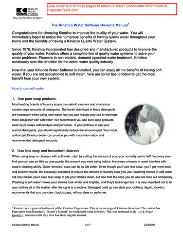
Freshly-drawnTraditionally ServedEnvironmentally FriendlyOwner’s ManualVi TAP Dispensing SystemMODELSVi TAP- 2Vi TAP- 2HVi TAP- 2HD170120Specially Branded
IMPORTANTThe information contained in this manual is specific toyour system. It is IMPORTANT you READ, FOLLOW andUNDERSTAND the instructions given.This manual and all material provided with your systemshould be retained in a convenient location for futurereference.Contact Vivreau if you have any questions regardingthe information contained in this manual. 2017 Vivreau USAAll rights reserved.Any and all information contained within this document issubject to change without prior notice.2Vi Tap Dispensing System Owner’s Manual
TABLE OF CONTENTSSAFETY PRECAUTIONS .5GENERAL INFORMATION.7TECHNICAL SPECIFICATIONS.9PRE-INSTALLATION REQUIREMENTS. 11OPERATING INSTRUCTIONS.13MAINTENANCE.17TROUBLESHOOTING.23Vi Tap Dispensing System Owner’s Manual3
4Vi Tap Dispensing System Owner’s Manual
Section 1Safety PrecautionsSAFETY PRECAUTIONSIMPORTANTThis manual is intended for use only bypersonnel trained in the operation of theVivreau ViTAP Dispensing System.WARNING Improper installation, adjustment,alteration, service or maintenance can causeproperty damage, injury, or death. Read theinstallation, operating, and maintenanceinstructions thoroughly before installing,operating, or maintaining this equipment.WARNING Keep the area around the unitclear of any combustible materials.WARNING Do not store or use gasolineor other flammable vapors or liquids in thevicinity of this or any other unit.IMPORTANTCarefully read, understand and follow allsafety instructions in this manual and safetylabels on the unit. Keep safety labels in good condition andreplace missing or damaged items. Learn how to operate the unit and how to usethe controls properly. Do not let anyone operate the unit withoutproper training. In the event of a power failure, do notattempt to operate this unit. Keep unit in proper working condition anddo not allow unauthorized modifications tothe unit.WARNING Only trained and certified electrical,plumbing and refrigeration technicians shouldservice this unit.SAFETY PRECAUTIONSThis unit has been specifically designed toprovide protection against personal injury.To ensure continued protection observethe following:WARNING Disconnect power to the unitbefore servicing. Follow all LOCKOUT/TAGOUTprocedures. Verify power to the unit is OFF anddisconnected before any work is performed. Failureto do so could result in serious injury, death orequipment damage. To protect against electric shock, do notimmerse power cord in water or otherliquid. To prevent damage to the power cord, donot allow cord to hang over the edge of atable or counter, or come in contact withhot surfaces. Isolate unit from power supply (unplug orturn OFF breaker) and turn OFF the watersupply when not in use and before cleaning. Allow Boiler (if supplied) to cool beforeremoving any components. The use of spare parts and accessoriesnot recommended by Vivreau may causedamage and/or injuries. Do not operate any unit with damagedcords, plugs, or after the unit malfunctionsor has been damaged in any manner. Do not use outdoors. Do not place on or near a hot gas or electricburner. Do not use the unit for anything other thanits intended use. Save these instructions.WARNING ALL WIRING AND PLUMBINGMUST CONFORM TO NATIONAL AND LOCALCODES. FAILURE TO COMPLY COULD RESULTIN SERIOUS INJURY, DEATH OR EQUIPMENTDAMAGE.Vi Tap Dispensing System Owner’s Manual 5
Section 1Safety Precautions6Vi Tap Dispensing System Owner’s Manual
Section 2General InformationGENERAL INFORMATIONINFORMATION FOR THE READERPURPOSE OF THE MANUALTo find specific topics of interest quickly, referto the Table of Contents at the beginning of thismanual. Vivreau has produced this manual to providenecessary information to qualified andauthorized personnel for the safe and properinstallation, operation, and maintenance ofthe Vivreau ViTAP-2, ViTAP-2H and ViTAP-2HDDispensing Systems. Information contained in this manual willhelp prevent risks to health and safety, andthe risk of economic losses. Keep this manual in a clearly identified andsafe place throughout the working life of theunit, so that it will always be available asneeded. The manufacturer reserves the right tomake modifications to the unit without anyobligation to provide prior notice. A number of symbols have been used tohighlight particularly important parts ofthe text or important specifications. Theirmeaning is as defined below.This manual is solely for the use of personneltrained in the operation of the ViVreau ViTAPDispensing System only.DANGERINDICATES AN IMMINENTLY HAZARDOUSSITUATION WHICH, IF NOT AVOIDED, WILLRESULT IN DEATH OR SERIOUS INJURY.WARNINGIndicates that suitable procedures must beadopted to avoid putting people’s health andsafety at risk or causing economic losses.CAUTIONIndicates a potentially hazardous situationwhich, if not avoided, may result in propertydamage, minor or moderate injury.IMPORTANTIndicates important technicalwhich must not be overlooked.informationVi Tap Dispensing System Owner’s Manual 7
Section 2General Information8Vi Tap Dispensing System Owner’s Manual
Section 3Technical SpecificationsTECHNICAL SPECIFICATIONSGENERAL DESCRIPTIONThe Vivreau ViTAP-2 (H/HD) is a self-service WaterDispensing System designed for under-counterinstallation with the Dispenser Head mounted tothe countertop directly above the unit.The system is made up of several components(depending on model) that will fit under a standardbase-cabinet section that is 30” wide (min.)Dispensing -2HViTap-2HDChilled still waterΔT 18 F @ 15.8 gal/hüüüChilled sparkling waterΔT 18 F @ 15.8 gal/hüüü203 FNAüü0.5 gal/hNAüü1.2 gal.NAüü5 PSIüüüSpecificationViTap-2ViTap-2HViTap-2HD60 – 90 Füüü60% 2”üüüPSI (min.)50üüüGPH (min.)80üüü60 FüüüRequirementsViTap-2ViTap-2HViTap-2HD65 – 70 PSIüüü100 PSI ight13”üüüDistance Nozzle to Drip Tray9.6”üüüWeight7.4 lbüüüHot waterHot water, immediate dispenseHot water, storage capacityWater Pressure at Dispensing HeadOperating ConditionsDescriptionTemperatureRelative HumidityWater Supply RequirementsDescriptionFNPT connection with Ball ValveTemperature (max.)CO2 Operating PressureDescriptionPressureSupply pressure (Bulk System)Dispensing Head SpecificationsDescriptionVi Tap Dispensing System Owner’s Manual 9
Section 3Technical SpecificationsCooler/Carbonator 18.5”üüüWeight39.6 lb.üüüVoltage110/120 VAC/60 5”NAüüWeight30.8 lbNAüü110/120 VAC/60 HzNAüNA230/240 VAC/60 HzNANAü13ANAüNA11ANANAüAmperageBoiler SpecificationsDescriptionVoltageAmperage10 Vi Tap Dispensing System Owner’s Manual
Section 4Pre-Installation RequirementsPRE-INSTALLATION REQUIREMENTSPRE-INSTALLATIONCO2Below are the services required to be in placeprior to the installation of the Vivreau ViTAPDispensing System. If you have any questionsregarding these or other services, please contactVivreau Service Toll-Free at 877-999-1044.CO2 Cylinder (Customer supplied) - Size shouldbe selected based on available space.WATER SUPPLYA potable 1/2” cold water supply terminating ina 1/2” Ball Valve, 1/2” female pipe thread.IMPORTANTBall Valve must be accessible for serviceand installation.Minimum Water Pressure: 50 PSIMinimum Water Flow: 80 gallons per hourIMPORTANTThe Vivreau ViTAP Dispensing Systemincorporates backflow prevention. Any additionalbackflow devices required by State or LocalCode must also be supplied by the customerprior to installation. There must not be anyother Filters/Pre-Filters inline before the unit.ELECTRICAL OUTLETModel ViTAP-2(1) 15 Amp Electrical Recepticle (NEMA 5-15R)120V, 60 Hz (11 Amps)Model ViTAP-2H(1) 15 Amp Electrical Recepticle (NEMA 5-15R)120V, 60 Hz (11 Amps)(1) 20 Amp Electrical Recepticle (NEMA 5-20R)120V, 60 Hz (13 Amps)NOTE: If connecting to a bulk or existing CO2system, a CO2 line terminating at a 1/4” BarbedShutoff Valve must be available within 40” ofthe unit with 100 PSI minimum pressure.DRIP TRAY AND DISPENSING HEADCUTOUTSCut out the holes for the DripTray and DispensingHead per the supplied template.NOTE: The Dispensing Head must be mountedon the work surface directly above the Chiller/Carbonator.DRIP TRAY DRAINDrip Tray must be plumbed to a drain. Customerwill need to supply a drain according to Stateand Local Codes. Drain must be at least 1-1/4” ID.LOCATION OF SERVICESAll services must be accessible for installationand service. Ensure all services are kept within40” of the ViTAP Dispensing System.Water Shutoff Valve to be located at low level.Ensure there is sufficient room for a 6” longfitting to be connected to the Water Shutoff Valve.Top of drain should be located between 12” and18” from floor level.SHIPPING DAMAGE/MISSING PARTSUnpack and inspect the unit for shippingdamage and/or missing parts. If any damageor missing parts are found, contact VivreauService Toll-Free at 877-999-1044 and reportthe missing or damaged parts.Model ViTAP-2HD(1) 15 Amp Electrical Recepticle (NEMA 5-15R)120V, 60 Hz (11 Amps)(1) 20 Amp Electrical Recepticle (NEMA L6-20R)230V, 60 Hz (11 Amps)NOTE: ViTAP-2HD will not operate on 208 VAC.All outlets must be mounted high in the cabinetto avoid accidental contact with water.Vi Tap Dispensing System Owner’s Manual11
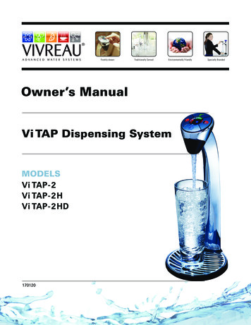
Section 4Pre-Installation RequirementsLOCATIONDISPENSING HEADA suitable location should be chosen within 40”of the electrical and water supply connections.The Dispensing Head with Integral Drip Trayis installed into a countertop directly over theChiller/Carbonator and Boiler (if equipped)using the supplied template.2”Rear2”Open61/2"Above11/4"Tap HoleDo not obstruct air vents.11/4"3/16"Right sideDrain HoleCL21/2"Install the system on a firm, level floor or base.R 2 11/16"1 15/16"2”23/4"Left side11/4"Installation Clearance for Chiller UnitCL3/16" x 2 placesFrontMounting HolesVENTILATION2 3/8"If the system is to be installed in an enclosedspace or in a cabinet, adequate ventilation mustbe provided. Ventilation must be at the top andbottom of the enclosure for proper air flow.5 3/8"Dispensing Head TemplateCAUTION Failure to provide adequateventilation will cause system failure.2"45/8"2"41/2"51/8"Available VIVREAU Grille45/8"This unit is to be installed indoors only.113/4"3/8"PLEASE NOTEAll vents must open to fresh airin a free and unobstructed area.Front VentilationShowing ventilationgrilles cut in a standarddoor panelSide VentilationVentilation grilles cut in the side of astandard 24" cabinet. The grilles may befitted on either side, provided they ventilateinto a free, unobstructed area.Base VentilationVentilation grilles cut in the cabinet's base panel and baseplinth. Top ventilation will also be required in either the sidepanels or a cut-out in the top of the door.Base CutoutVentilation can be made through the base of the cabinet, with the removal of anarrow section of floor immediately behind the door. Trim with roll edgingstrip. Cut-out size must not be less than 11.0" wide x 1.5" deep.Ventilation Options12 Vi Tap Dispensing System Owner’s Manual11"Cut-out detail for theVIVREAU grille, shown ina 23.5" (24") wide door
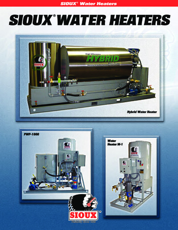
Section 5OperationOPERATING INSTRUCTIONSThe ViTAP Dispensingdesigned for ease of use.SystemhasbeenIMPORTANTLED DISPLAY PANELThe LED Display Panel is located on the frontpanel of the Chiller/Carbonator.Before operating the ViTAP Dispensing System,make sure the water supply is turned ON andthe unit is plugged in.BEFORE USELED PanelALWAYS sanitize your hands.ALWAYS wear hygienic gloves.ALWAYS remove anti-bacterial cling film fromthe Dispensing Head.ALWAYS wipe Dispensing Head, Nozzles, DripTray and cabinet work-surface with anti-bacterialwipes.Dispensing Head System LED Display PanelPOWER: When the Dispensing Head System isplugged in and turned ON, a Blue LED will beilluminated.CHANGE CO2: When the CO2 supply is low, aRed LED will illuminate and the unit will beep;alerting you to change the CO2 Cylinder.CALL SERVICE: If there is a problem, a Red LEDwill illuminate and the unit will beep. Pleasecontact Vivreau Service Toll-Free at 877-9991044 immediately.EMPTY DRIP TRAY: (Not Activated on this Unit):When the Drip Tray Container is FULL, a Red LEDwill illuminate and the unit will beep; alertingyou to empty the Drip Tray Container locatedjust inside the cabinet front door or below theDispensing Head System.Vi Tap Dispensing System Owner’s Manual13
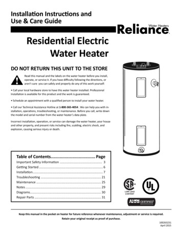
Section 5OperationDISPENSINGIMPORTANTBefore operating the ViTap Dispensing System,make sure the Water Supply Valve is open andthe unit is plugged in.Hot Water (if supplied)As a safety feature, to dispense Hot Water, Touchand Release either Red Button, then Press and Holdthe opposite side Red Button within 3 seconds.Release the button when filled.1DISPENSING2ORBefore operating the ViTAP Dispensing System,make sure the Water Supply Valve is open andthe Chiller (and Boiler, if supplied) is plugged in.Place appropriate container on Drip Tray beneaththe Dispensing Head.Chilled Still Water3Within 3 Sec.ORPress and Hold the Blue Button to dispensewater. Release the button when filled.Dispensing Hot WaterWARNING Water is Hot! Do not place handsor other body parts beneath Dispensing Headwhen dispensing hot water.AFTER DAILY USEDispensing Chilled Still WaterRemove Dispensing No
Vi Tap Dispensing System Owner’s Manual 5 Section 1 Safety Precautions SAFETY PRECAUTIONS IMPORTANT _ This manual is intended for use only by personnel trained in the operation of the Vivreau ViTAP Dispensing System. WARNING Improper installation, adjustment, alteration, service or maintenance can cause property damage, injury, or death. Read the installation, operating, and