Transcription
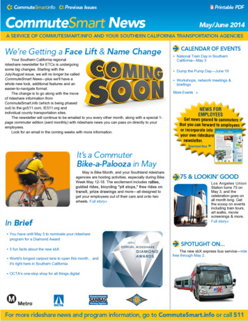
MOUNTAIN BIKEOWNER’SMANUALTHIS MANUAL CONTAINS IMPORTANT SAFETY, PERFORMANCE AND MAINTENANCE INFORMATION. READ THE MANUAL BEFORE TAKING YOUR FIRSTRIDE ON YOUR NEW BICYCLE, AND KEEP THE MANUAL HANDY OF FUTURE REFERENCE.DO NOT return this item to the store.Questions or comments?1-800-551-0032NOTE: Illustrations in this Manual are for reference purposes only and may not reflect the exact appearance of the actual product. Specifications are subject to change without notice.
HELMET USE & GENERAL MANUAL DISCLAIMERNOTE: The illustrations in this manual are used simply to provide examples; the components of your bicycle might differ. Inaddition, some of the parts shown might be optional and not part your bicycle’s standard equipment.The following manual is only a guide to assist you and is not a complete or comprehensive manual of all aspects ofmaintaining and repairing your bicycle. If you are not comfortable, or lack the skills or tools to assemble the bicycle yourself,you should take it to a qualified mechanic at a bicycle shop. Additionally, you can write or call us concerning missing parts orassembly questions.WARNING/IMPORTANT: Take notice of this symbol throughout this manual and pay particular attention to theinstructions blocked off and preceded by this symbol.Dynacraft 1-800-551-0032289 South Kelly Road, American Canyon, CA 94503www.dynacraftbike.com
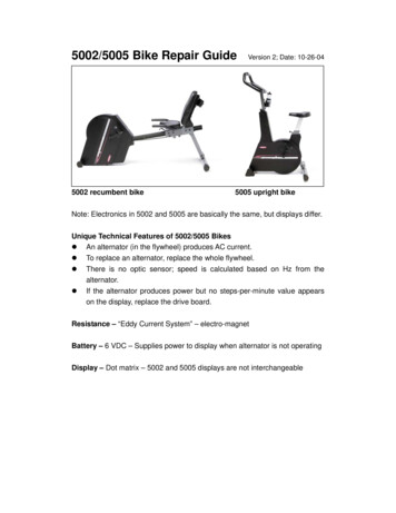
HELMETS SAVE LIVES!WARNING: Always wear a properly fitted helmet when you ride yourbicycle. Do not ride at night. Avoid riding in wet conditions.Correct fittingMake sure your helmet coversyour forehead.Incorrect fittingForehead is exposed and vulnerableto serious injury.3
ABOUT THIS MANUALThis manual was written to help you get the most performance, comfort, enjoyment and safety when riding your new bicycle.It is important for you to understand your new bike. By reading this manual before you go out on your first ride, you’ll knowhow to get the most from your new bicycle. It is also important that your first ride on your new bicycle is taken in a controlledenvironment, away from cars, obstacles, and other cyclists.GENERAL WARNINGBicycle riding can be a hazardous activity even under the best of circumstances. Proper maintenance of your bicycleis your responsibility as it helps reduce the risk of injury. This manual contains many “WARNINGS” and “CAUTIONS”concerning the consequences of failure to maintain or inspect your bicycle. Many of the warnings and cautions say, “youmay lose control and fall.” Because any fall can result in serious injury or even death, we do not repeat the warning ofpossible injury or death whenever the risk of falling is mentioned. Dynacraft does not encourage stunting, trick riding, rampriding, jumping, aggressive riding, riding on severe terrain, riding in severe climates, riding with heavy loads, riding double,commercial activities; such use is inherently dangerous, can cause serious injury to the rider, and if done it is with the rider’sexpress and implied assumption of the risk of such use and Dynacraft shall not have any responsibility for any breakdown ofthe bicycle, its components or rider injuries that occur during such use.NOTE TO PARENTSIt is a tragic fact that most bicycle accidents involve children. As a parent or guardian, you bear the responsibility for theactivities and safety of your minor child. Among these responsibilities are to make sure that the bicycle that your child isriding is properly fitted to the child; that it is in good repair and safe operating condition; that the play of young childrenis supervised by an adult; that you and your child have learned, understand and obey not only the applicable local motorvehicle, bicycle and traffic laws, but also the common sense rules of safe and responsible bicycling. As a parent, you shouldread this manual before letting your child ride the bicycle. Please make sure that your child always wears an approvedbicycle helmet when riding.4
CONTENTSA ABOUT YOUR BIKE . . . . . . . . . . . . . . . . . . . . . . . . . . . . . . 7Model/Serial Number Identification . . . . . . . . . . . . . . . . . . . 7Customer Service . . . . . . . . . . . . . . . . . . . . . . . . . 7Spaces to Write Info . . . . . . . . . . . . . . . . . . . . . . . . . 7B BEFORE YOU RIDE . . . . . . . . . . . . . . . . . . . . . . . . . . . . . . 8Parts List . . . . . . . . . . . . . . . . . . . . . . . . . . . . . 8Tool List . . . . . . . . . . . . . . . . . . . . . . . . . . . . . 9Frame Sizing . . . . . . . . . . . . . . . . . . . . . . . . . . 10Rules of the Road/Safety Tips . . . . . . . . . . . . . . . . . . . . 11Night Riding . . . . . . . . . . . . . . . . . . . . . . . . . . . 13Safety Checklist . . . . . . . . . . . . . . . . . . . . . . . . . 14C BICYCLE ASSEMBLY . . . . . . . . . . . . . . . . . . . . . . . . . . . . 16Getting Started . . . . . . . . . . . . . . . . . . . . . . . . . .1. Pedals . . . . . . . . . . . . . . . . . . . . . . . . . . .2. Seat . . . . . . . . . . . . . . . . . . . . . . . . . . . .3. Testing Seat Clamp and Post Clamp Tightness . . . . . . . . . . . . .4. Handlebar/Stem . . . . . . . . . . . . . . . . . . . . . . . .5. Testing Handlebar and Stem Tightness . . . . . . . . . . . . . . .6. Front Wheel . . . . . . . . . . . . . . . . . . . . . . . . .7. Brakes . . . . . . . . . . . . . . . . . . . . . . . . . . .8. Testing Brake Functions . . . . . . . . . . . . . . . . . . . . .9. Dual Suspension . . . . . . . . . . . . . . . . . . . . . . . .10. Tire inflation . . . . . . . . . . . . . . . . . . . . . . . . .11. Reflectors . . . . . . . . . . . . . . . . . . . . . . . . . .12. Accessories . . . . . . . . . . . . . . . . . . . . . . . . .161718192023242527283031325
D BICYCLE ADJUSTMENTS. . . . . . . . . . . . . . . . . . . . . . . . . . 33Seat Adjustment . . . . . . . . . . . . . . . . . . . . . . . . .Stem Adjustment . . . . . . . . . . . . . . . . . . . . . . . . .Handlebar Adjustment . . . . . . . . . . . . . . . . . . . . . . .Brake Adjustment . . . . . . . . . . . . . . . . . . . . . . . . .Shifter Adjustment . . . . . . . . . . . . . . . . . . . . . . . .Derailleur Adjustment . . . . . . . . . . . . . . . . . . . . . . .333435363839E MAINTENANCE AND INSPECTION . . . . . . . . . . . . . . . . . . . . .40Tire Removal/Seating . . . . . . . . . . . . . . . . . . . . . . . 41Lubrication . . . . . . . . . . . . . . . . . . . . . . . . . . . 42Bearing Inspection . . . . . . . . . . . . . . . . . . . . . . . . 43F LIMITED WARRANTY. . . . . . . . . . . . . . . . . . . . . . . . . . . . 446
ABOUT YOUR BIKEAMODEL/SERIAL NUMBER IDENTIFICATIONEach Dynacraft bicycle has a serial number stamped into the frame. The serial number can be found on the bottom of thecrank housing as shown (see diagram below). The model number and production date are found on a sticker on the frame atthe bottom of the seat tube. When contacting Dynacraft, please have these two numbers ready.Model #CUSTOMER SERVICEDYNACRAFT CUSTOMER SERVICE1.800.551.00327 AM to 4 PM PACIFIC TIMESerialNumberDynacraft BSC, Inc.Please retain your sales receipt as proof of purchase. Fill out the information below and keep this manual in a safe place.Brand/DescriptionModel #Production DateSerial #Date of PurchaseStore/Place of Purchase7
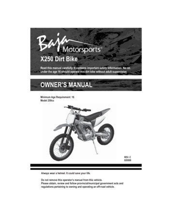
BXPARTS/TOOLS LISTS1. Frame2. Brake Lever (L and R)3. Handlebar4. Grip (L and R)5. Front Reflector6. Stem7. Head Tube8. Front Brake9. Brake Pad (x4)10. Fork11. Tire (x2)12. Tube (x2)13. Locking Washer (x2)14. Wheel Reflector (x2)15. Locknut (x4)16. Headset17. Front Derailleur18. Crankset19. Rear Derailleur20. Rear Cassette21. Pedal (L and R)22. Seat Clamp23. Rear Reflector24. Saddle25. Seat Post26. Rear Brake27. Derailleur Guard28. Gear Shifters (L and R)29. Front Wheel30. Rear Wheel31. Chain32. Stem BoltTools RequiredABCDEFA. Standard Phillips Head ScrewdriverB. Adjustable WrenchC. 4, 5, 6, 8mm Allen WrenchesD. Pedal wrench or 15mm Open End WrenchE. Standard Slip Joint PliersF. Standard Flat Head Screwdriver9
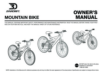
BFRAME SIZINGWhen selecting a new bicycle, the correct choice of frame size is a veryimportant safety consideration. To determine the correct size bicycle forthe rider: Straddle the assembled bicycle with feet shoulder width apart andflat on the ground There must be at least one inch (2.5cm) of clearance between thehighest part of the top tube of the bicycle and the crotch of the riderwith the tires properly inflated. The standover height for each bike is listed in the information centeron the product page of every bike on www.dynacraftbike.com To measure the inseam, use measuring tape to measure from theground (with shoes on) to the inseam of your pants. Subtract the standover height from the inseam measurement toensure that you have the recommended amount of clearance. If youhave less than one inch or more than three inches (2.5 to 7.5 cm), youmay need to move up or down a frame size. For more detailed instructions on how to properly adjust your bike tofit you, visit our website at www.dynacraftbike.com, find your bike,and locate the fit video in the Information Center. (Disclaimer: Fitvideo not available for all products)WEIGHT LIMITThe maximum structural weight recommendations for our bicycles thatare 20 inches or larger are: 20 inch bicycles: 176 lbs. (80 kg) Adult bicycles up to 26 inches: 275 lbs. (125 kg)10CAUTION: For safe and comfortableriding there should be a clearance of no less than 1inch between the inseam area of the intended riderand the top tube of the bicycle frame, while therider straddles the bicycle with both feet flat on theground.WARNING: If the bicycle is too largethe rider cannot reach the pedals easily, or theground when stopping which may result in loss ofcontrol and/or injury.
RULES OF THE ROAD/SAFETY TIPSBNOTE:Like any sport, bicycling involves risk of injury and damage. By choosing to ride a bicycle, you assume the responsibility forthat risk; not the people who sold you the bike; nor the people who made it; nor the people who distribute it; nor the people who manage ormaintain the roads and trails you ride on. YOU. So you need to know – and to practice – the rules of safe and responsible riding.1. I N THE INTEREST OF SAFER CYCLING, MAKE SURE YOU READ AND UNDERSTAND YOUR OWNER’S MANUAL.NOTE AND PERFORM PRE-RIDE SAFETY CHECKS.2. NOTICE: Some state and local laws may require that your bicycle be equipped with a warning device such as a horn orbell and a front and rear light if the bicycle is to be ridden after dark.3. ALWAYS WEAR SHOES when riding a bicycle and AVOID LOOSE FITTING CLOTHES.4. CHECK YOUR BRAKES FREQUENTLY. THE ABILITY TO STOP YOUR BICYCLE IS CRITICAL. Roads are slippery whenwet so avoid sharp turns and allow more distance stopping. Caliper brakes may become less efficient when wet. Leaves,loose gravel, and other debris can also affect stopping.5. ALWAYS RIDE IN THE SAME DIRECTION AS TRAFFIC. Never ride against traffic.6. STOP AND LOOK BEFORE YOU LEAVE AN ALLEY, DRIVEWAY, OR PARKING LOT. Stop, look to the left, to the right, andto the left again for traffic. Ride only when it is clear.7. KEEP TO THE RIGHT. Follow the traffic flow in a straight line and stay close to the curb or in the bike lane, when available.Watch for cars moving in and out of traffic.8. OBEY ALL TRAFFIC LAWS REGULATIONS. Most traffic regulations apply to bike riders as well as automobile operators.9. ONE RIDER PER BIKE. NEVER CARRY OTHER RIDERS. This is dangerous and makes the bike harder to control. Thebicycles distributed by Dynacraft BSC, Inc. are intended for one rider only.11
B10. ALWAYS BE ALERT. BE ALERT – pedestrians have the right of way. BE ALERT – when riding near parked cars - ride farenough away from the cars so that you won’t get hit if someone opens the car door.11. USE CAUTION AT ALL INTERSECTIONS AND STOP SIGNS. STOP AND LOOK BOTH WAYS BEFORE PROCEEDING.12. USE HAND SIGNALS. Communicate by using hand signals to tell other drivers what you are going to do. Signal 100 feetbefore turning unless your hand is needed to control the bike.13. PROPER LIGHTS ARE RECOMMENDED IF YOU RIDE AT NIGHT. Be sure to have a strong head-light, a tail light, and a fullset of reflectors. CHECK THAT REFLECTORS ARE CLEAN, STRAIGHT, UNBROKEN, AND SECURELY MOUNTED.14. NEVER CARRY PACKAGES OR OBJECTS WHICH OBSTRUCT VISION.15. NEVER HITCH RIDES, never hold onto a moving vehicle while riding.16. THE KICKSTAND IS DESIGNED TO SUPPORT THE BICYCLE ONLY, not the bicycle and the rider.17. AVOID THE FOLLOWING HAZARDS: Drain grates, potholes, soft road edges, gravel, sand, wet leaves, and/or anyobstruction in the road. Failure to do so could cause wheel(s) to buckle and result in personal injury to the rider.18. WET WEATHER RIDING - Riding your bicycle in wet conditions is not recommended. In wet conditions traction andbraking power is reduced. Riding in such conditions could result in personal injury.19. PROPER HELMET USE. A helmet that meets the CPSC (Consumer Product Safety Commission) standard should alwaysbe worn when riding a bicycle. The helmet should fit properly and be worn on the crown of the head, not tipped back.Ensure to replace your helmet at least every three years to ensure the structural integrity of the foam. Replace afterimpact, regardless of lack of visible damage to helmet.20. USE BIKE LANES when available. Also note that in certain states, cars may use bike lanes when turning.1221. RESPECT “Bicycles Are Prohibited” SIGNS.
NIGHT RIDINGBRiding a bicycle at night is much more dangerous than riding during the day. A bicyclist is very difficult for motorists andpedestrians to see. Therefore, children should never ride at dawn, dusk or at night. Adults who choose to accept thegreatly increased risk of riding at dawn, dusk or at night need to take extra care both riding and choosing specializedequipment which helps reduce that risk. Consult your dealer about night riding safety equipment.WARNING: Reflectors are not a substitute for required lights. Riding at dawn, at dusk, at night or at other times of poorvisibility without an adequate bicycle lighting system and without reflectors is dangerous and may result in serious injury or death.WARNING: Do not remove the front or rear reflectors or reflector brackets from your bicycle. They are an integral part ofthe bicycle’s safety system. Removing the reflectors reduces your visibility to others using the roadway. Being struck by other vehiclesmay result in serious injury or death.RULES FOR CHILDRENTo avoid an accident, teach children good riding skills with an emphasis on safety from an early age.1.2.3.4.5.6.7.8.9.Always wear a properly fitted helmet.Do not play in driveways or the road.Do not ride on busy streets.Do not ride at night.Obey all traffic laws, especially stop signs and red lights.Be aware of other road vehicles behind and nearby.Before entering a street: Stop, look left, right, and left again for traffic.If riding downhill, be extra careful. Slow down using the brakes and maintain control of steering.Never take your hands off the handlebars, or your feet off the pedals when riding downhill.CAUTION: The Consumer Product Safety Commission advises that the riding of small wheel diameterbicycles at excessive speeds can lead to instability and is not recommended.13
BXSAFETY CHECKLISTBefore every ride, it is important to carry out the following safety checks: (For information and instructions on performingspecific equipment checks, locate the relevant section in the manual referenced on pages 5–6.)1. BRAKES Ensure front and rear brakes work properly. Ensure brake pads are not over worn and are correctly positioned in relation to the rims. Ensure brake control cables are properly lubricated, correctly adjusted, and display no obvious wear. Ensure brake control levers are properly lubricated and tightly secured to the handlebar.2. DERAILLEURS Check that the front and rear derailleurs are adjusted and functioning properly.Ensure that the shifter levers are securely attached.Ensure that derailleurs, shift levers, and control cables are properly lubricated.Shift through all the gears while pedaling to ensure that the derailleurs are adjusted and functioningproperly.3. CRANKS AND PEDALS Ensure pedals are securely tightened to the cranks. Ensure cranks are securely tightened to the bottom bracket and are not bent.4. FRAME AND FORK Check that the frame and fork are not bent, broken, or cracked. If either are found to be bent, broken, or cracked, they should be replaced.14
BX5. WHEELS AND TIRES Ensure tires are inflated to within the recommended range as displayed on the tire sidewall. Ensure tires have tread and have no bulges or excessive wear. Ensure rims run true and have no obvious wobbles or kinks. Ensure all wheel spokes are tight and not broken. Check that axle nuts are tight. Do not over inflate.6. CHAIN Ensure chain is oiled, clean and runs smoothly. Extra care is required in wet or dusty conditions. On bicycles equipped with coaster brakes, check for proper chain tension. Check to make sure your chain guard is tight and not touching the crank or chain.7. BEARINGS Ensure all bearings are lubricated, run freely and display no excess movement, grinding or rattling. Check headset, wheel bearings, pedal bearings and bottom bracket bearings.8. STEERING Ensure handlebar and stem are correctly adjusted and tightened, and allow proper steering. Ensure that the handlebars are set correctly in relation to the forks and the direction of travel.15
CBICYCLE ASSEMBLYGETTING STARTEDOpen the box and check that all parts are present. You can check against thelist on page 9. If any parts are missing or damaged, or if you have any troublewith the assembly, don’t return the item to the store. Call Dynacraft directlyat 1-800-551-0032 or visit our website at www.dynacraftbike.com, find yourbike, and locate the assembly video in the Information Center. (Disclaimer:Assembly video not available for all products).We strongly recommend reading the manual before beginning. If you aren’tcomfortable with the assembly, you should bring your new ride to your localbike shop to have a qualified mechanic put it together for you. In any event,you need to read this entire Owner’s Manual before you ride or let anyone elseride it.CAUTION:Figure 1As you assemble the bike, it’s a good idea to place a little whitegrease or anti-seize compound on the seatpost, stem and threads of the bolts toprevent rusting.You’ll see that the frame, handlebars, front wheel, and other componentsare attached with zip ties. Lift everything out in one piece, and set it down,with the chain facing upwards. Cut the zip ties, and remove any padding orpackaging.First, align the fork. Rotate it, to ensure it moves freely without binding (seeFigure 1), making sure the fork is pointing in the right direction, with the forkblades facing forward (see Figure 2).16Figure 2
1. PEDALSCWARNING: Attachment of an incorrect pedal into a crank arm willcause irreparable damage. Unless the shoulder of the pedal spindle is tight to theface of the crank arm, the pedal may back out causing serious injury or death. Makeit tight so the shoulder is in complete contact with the surface of the crank arm.Before your first ride, please check to ensure your pedals are attachedcorrectly. There is a right side pedal marked “R” and a left side pedal marked “L”The right pedal has a RED sticker, the Left pedal has a GREEN sticker.Pedal marked “R” has right hand threads. Tighten in a clockwise direction.Pedal marked “L” has left hand threads. Tighten in a counterclockwisedirection (see Figure 3).After putting some white grease on the threads of the pedal, place thepedal into the crank, and use your fingers to get it started. Threading it incan be tricky, so make sure to do it correctly. Regardless of which sideyou’re working on, the top of the thread will rotate towards the front ofthe bike to tighten the pedals. Once you’ve finger tightened the pedals,use a 15mm open-ended wrench to snug them down. They are properlytightened when the pedal spindle, which is the axle that the pedalplatform spins around, begins to bite into the metal on the crank.Figure 3If you have a three piece crank, check the crank bolts to make sure theyare tightened (see Figure 4). Re-check the bolts after your first ride.If you have a one piece crank, firmly grasp the crank arm on the left sideof the bicycle and wiggle it gently. If there is any movement or play in thecrank, use a 15 mm open-ended wrench to tighten the locknut. Repeatthe process until there is no more play in the crank, being careful not toovertighten (see Figure 5).WARNING:Never ride your bike if the cranks are loose. This coulddamage the crank arms beyond repair, and result in a loss of control, injury or death.Figure 4Figure 517
C2. SEATWARNING: The seatpost must be inserted far enough so that the minimuminsertion marks cannot be seen.Add some white grease to the inside of the seat tube, and slide the seatpostinto the bicycle. Make sure that the minimum insertion mark is completelycovered and that the seat is pointing forward in alignment with the bicycle(see Figures 6 and 7).CAUTION:Figure 6SeatpostSeat tubeOperate the quick release lever by hand only. Do not use ahammer or any other tool to tighten the quick release lever.WARNING:If the quick release lever is not tightened properly, theseatpost can loosen while riding. This can cause a loss of control and injury to therider or others.Minimum insertion marks arelocated on the seatpostFigure 7To install the seat post reflector, first remove the seatpost and saddle fromthe bike. Use (A) Standard Phillips Head Screwdriver to loosen the screw onthe clamp of the reflector until you can slide the reflector over the seat post.Once the reflector is on the seat post, reinsert the seat post back into theseat tube. Position the reflector so that it is perpendicular to the ground, andmove it up on the seat post until it can be seen above the tire when viewingthe bike from the rear (see Figure 8).18Figure 8
CIf your bike has a quick release lever (see Figure 9), tighten it by holding thelever in the “open” position and tightening the nut on the opposite side byhand. Slowly close the quick release lever, and you should notice resistancewhen the lever is half way shut. Firmly continue to push the lever until it is inthe “closed” position, and the word “close” is showing. The seat should notbe able to move back and forth, up and down, or side to side with the quickrelease lever in the closed position. Make sure the lever is also parallel with theseat clamp itself. You should only need one hand to close the quick releaselever. If you need two hands, the seat clamp is too tight. Loosen the nut on theclamp until only one hand is needed to close the seat clamp.ClosedOpenFigure 9If your bike has a standard seat clamp (see Figure 10), use (B) an AdjustableWrench(es) to tighten the nut securely. If your bike has a bolt on seat clamp(see Figure 11), use (C) a 4, 5, or 6 mm Allen Wrench to tighten the boltsecurely. The seat should not be able to move back and forth, up and down, orside to side with the seat clamp tightened.Figure 10Figure 11Figure 12Figure 133. TESTING SEAT CLAMP AND POST CLAMPTIGHTNESSAfter installing the seatpost into the bicycle and tightening the clamp, test thetightness of the saddle. Hold the saddle firmly with both hands and try to moveit side to side. The seatpost should not move at all. The seatpost and saddlealso should not move when the rider is seated. Make sure the seat clamp nutsat the top of the seatpost are tight so that the seat does not tip forward orbackwards (see Figures 12 & 13).19
C4. HANDLEBAR/STEMMinimuminsertionmarkWARNING:To prevent steering system damage and possible loss of control, thestem must be inserted enough so that the minimum insertion marks are completely covered(see Figure 14).Add some white grease to the inside of the fork steerer tube. Before installing thestem, ensure that you have all the parts present and installed in the correct order(see Figure 17). For a threaded or quill stem, remove the plastic shipping cap fromthe bottom of the stem (see Figure 15).Figure 14Fork ConeLocknutWasherAdjustableCupBall RetainerInsert the stem and handlebar assembly into the fork, making sure the stem wedgeis loose (see Figure 16). Make sure the cables are not tangled and track smoothlyon either side of the stem.Bearing CupBearing CupRemovecapBall RetainerFork Cone20Figure 15Figure 16Figure 17
Pre-LoadBoltThe stem should be pointing towards thefront of the bike, aligned with the front tire(see Figure 18). Depending on the type ofbolt, tighten the stem bolt with either (B)an adjustable wrench or (C) a 4, 5, or 6 mmAllen wrench (see Figure 19).Top CapStemFigure 18If your bicycle comes with a threadlessstem (see Figure 20), we must first removethe headset in order to install. Use (C) a 4,5, or 6 mm Allen wrench to remove the preload bolt, cap and cardboard spacer fromthe headset. Discard the cardboard spacer(see Figure 22).Loosen the bolts on the side of the stem,slide the stem into place, making sure itlines up with the fork (see Figure 18). Checkthe gap between the steerer tube and stem,ensuring there is enough space to reinstallthe cap and bolt. (See Figure 21) If you needit higher or lower, your local bike mechaniccan help you out with the adjustment. Snugthe pre-load bolt on top. Then tighten thetwo bolts on the side of the stem, alternatingeach bolt.CSpacerBearingSpacerCupFigure 22Figure 19Figure 20Figure 2121
CThe handlebars should come attached to the stem.Simply ensure that the brake and derailleur cables tracksmoothly, and that the handlebar bolt(s) are properlytightened with (C) a 4, 5, or 6 mm Allen Wrench. (SeeFigures 23-25). In the case of a 2 or 4-bolt stem, tightenthe bolts alternating between bolts every few turns. Wewill adjust the position and rotation of the handlebars,brake levers, and shifters later on (see page 35).Figure 2322Figure 24Figure 25
C5. TESTING HANDLEBAR AND STEM TIGHTNESSTo test the tightness of the stem, straddle the front wheel between your legstightly (see Figures 26 & 27). Try to turn the handlebar back and forth. Thehandlebar should not slip or move independently of the front wheel at all. Ifthe handlebar does move, re-align the stem with the front wheel and tightenthe stem bolt. Re-test to make sure the stem is secure with the same process.To test the tightness of the handlebar, hold the bike stationary and try torotate the ends of the handlebar up and down or move the bar forward andback. If the handlebar moves, loosen the handlebar clamp nut or bolts evenlyto re-position and then re-tighten. Repeat the test until the bars will not move.Figure 26WARNING:To prevent steering system damage and possible loss ofcontrol, the stem and handlebars must be properly adjusted and tightened. DO NOTOVERTIGHTEN.Figure 2723
C6. FRONT WHEELBefore installing the front wheel, ensure that the brakes areopened enough to allow the tire to fit through them. On side-pullequipped bikes, you may have to loosen the cable anchor bolt(see Figure 31) in order to allow the tire to fit through. On LinearBrake equipped bikes, squeeze the brake arms together by hand,and lift the cable out of the carrier to open up the brakes (seeFigure 33).To install the front wheel, insert the wheel in the dropouts, placethe locking washer on the axle, line up the tab on the retainer clipwith the corresponding hole in the drop out. Place the locknuton the axle after the retainer clip and tighten the lock nut with (B)Adjustable Wrench (see Figures 28 & 29).WARNING:both nuts.Figure 28Put the wheel in the center of the fork and tightenWARNING: Failure to obey these steps can allow the frontwheel to loosen or dislodge while riding. This can cause injury or death tothe rider or to others.Drop-outRetainerClipLocknut24Figure 29
C7. BRAKESCableAnchor BoltWARNING:When assembling or adjusting thebrakes, make sure the cable anchor nut is tight. Failure tosecurely tighten the nut could result in brake failure andpersonal injury (see Figure 31).Brake armBrake pad7A. Side Pull BrakesAfter installing the front wheel, loosen the cableanchor nut and pull the brake cable through it.Squeeze the brake arms together against the rimof the wheel. While still holding the brake arms, pullthe cable firmly through the cable anchor nut andtighten the nut securely (see Figures 30 & 31). Tofine tune your brakes, see the adjustment section onpages 35-37.Brake cableFigure 30Figure 31CableCarrier7B. Linear Pull BrakesBrake CableCableAnchor NutAfter installing the front wheel, re-connect the frontbrake by squeezing the arms together, and slidingthe cable guide back into the carrier (see Figures 32& 33).Brake armBrake padFigure 32Figure 3325
C7C. Disc BrakesWhen installed properly, the disc brake rotor should be centeredbetween the brake pads, and securely fastened to the wheel (seeFigure 34)
mountain bike owner’s manual this manual contains important safety, performance and maintenance information. read the manual before taking your first ride on your new bicycle, and keep the manual handy of future reference. do not return this