Transcription
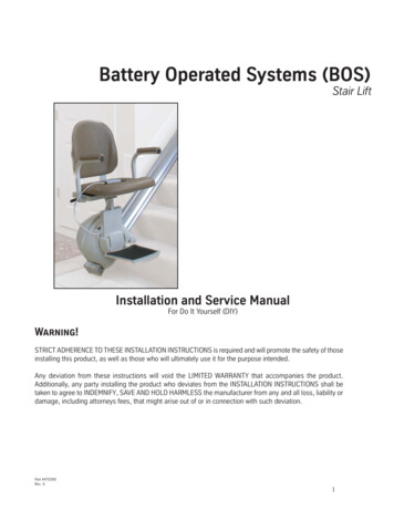
Battery Operated Systems (BOS)Stair LiftInstallation and Service ManualFor Do It Yourself (DIY)Warning!STRICT ADHERENCE TO THESE INSTALLATION INSTRUCTIONS is required and will promote the safety of thoseinstalling this product, as well as those who will ultimately use it for the purpose intended.Any deviation from these instructions will void the LIMITED WARRANTY that accompanies the product.Additionally, any party installing the product who deviates from the INSTALLATION INSTRUCTIONS shall betaken to agree to INDEMNIFY, SAVE AND HOLD HARMLESS the manufacturer from any and all loss, liability ordamage, including attorneys fees, that might arise out of or in connection with such deviation.Part #470280Rev. A1
This stair lift Installation and Service Manual has been writtento provide clear and precise instructions for proper installationprocedures of the Citia BOS stair lift.Please refer to the Owner's Manual for warranty information andoperating instructions. The Owner's Manual must be given tothe owner of the lift before it is put into service.by ThyssenKrupp Access may void the warranty.If you have questions concerning the installation or service ofthe Citia BOS please contact the Service Department:ThyssenKrupp Access4001 East 138th StreetGrandview, MO 64030800-409-3349Any alterations to the equipment without written authorizationTable of ContentsI.PRELIMINARY CHECKS .3A. Installation site requirements . 3B. Tools required . 3C. Shipment . 3II. TYPICAL COMPONENTS .4III. INSTALLATION PROCEDURES .4A. Time the gear rack . 5B. Determine where the track will be installed. 6An Introduction to T Bolts . 7C. Install the Lower End Cap . 8D. Install mounting hardware . 9E. Mount the track to the staircase .10F. Install the chassis assembly into the track .11G. Installing the fuse .13H. Test run the chassis .13I. Level the seat hub .14J. Install the seat .14K. Adjust seat height .15L. Remote control label .15M. Charging the batteries.15N. Changing the orientation of the pendant holster .15IV. COMPLETION PROCEDURES .16A.Completion Checklist .16V. E.T.L. REQUIREMENTS .17VI. SERVICE INFORMATION .18A.B.C.D.E.F.G.H.I.xxIM0805-4702512General specifications .18Standard equipment .18Control Board Operation Notes .19Control Board Diagnostics .19Charging Circuit .20Up/Down Logic .20Beep Alerts.20What to do if the lift is stuck on a final limit switch .20Troubleshooting Flowchart if lift won’t run .20Important! It is imperative that this manual be read and understoodprior to attempting installation of the stair lift. Also, please observeall cautions and warnings in this manual, as well as labels on theequipment.
I.PRELIMINARY CHECKSC.A.INSTALLATION SITE REQUIREMENTSVerify all components are included with theshipment:Dedicated* 115 VAC, 60 Hz, 3-wiregrounded outlet within 13’ of the top orbottom of the staircase.Stair angle between 25 and 45 .Must be installed INDOORS* NEC requirementB.TOOLS REQUIREDSet of Phillips head screwdriversTape measure3/8” reversible drill with 3/8” hex socket anda 6” extension3/16” Allen wrenchesTorque wrench rated to at least 18ft.lbs. oftorqueSafety items: steel toe shoes, safetyglasses, gloves, etc.Torpedo levelTools for removing hand rail if it interfereswith the travel of the stair lift13mm socketSHIPMENTSeat Box: Seat assemblyChassis Box: Chassis assembly (mounted to loading tool) (1) Power supply (2) Remote controls (2) 9 volt batteries for remote controls Unit small parts- (1) Set of Velcro - (1) FuseTrack Box: Track pieces (quantity will vary) with gear rackand splice bars Track brackets (quantity will vary) (1) Charging wire (2) Track end caps Small parts kit:- (1) Tube of lubricant- (1) 4” long piece of gear rack for splice timing- Fasteners for track brackets and track endcaps- Track bracket covers (quantity will vary)- Splice bars (to be placed in track, quantity willvary)1/2" combination wrench4mm Allen wrench (included)3mm Allen wrench (included)1/8" Allen wrenchSomething heavy to hold track in placeduring install.Mallet and flathead screwdriver3
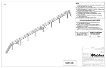
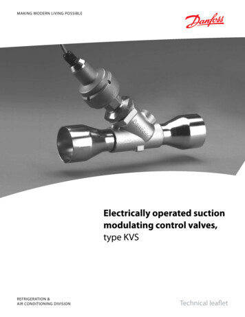
II. TYPICAL COMPONENTSUnit ControlSwivelSeatHandleFixed orFold-Up Seat(depends onmodel)Begin by laying out your track on the floor andremoving any plastic wrap that may be aroundthe track.NOTE: While we begin laying out the track on thefloor, some people may find it easier to lay outthe track on the staircase. If this is easier, youmay do it that way, however, make sure you havesomething heavy to keep the track from slidingdown the stairs.A stock unit may include as few as 1 or as manyas 4 custom cut sections of extruded aluminumtrack. The track is cut at the factory. Make surethe track is positioned so the bottom is facing up.You may have extra gear rack in your track. Gearrack should be installed on the SIDE of the track.If you have any gear rack placed in the BOTTOMof the track, use the supplied 3mm Allen wrenchand loosen, but do not remove, the bolts from thegear rack. Once loosened, slide the extra gearrack out of the track.Track with Gear Rack InstalledChassisFoldingFootrestPictured above is a "Supreme" model. This line of stairlifts features interchangeable seats. The seat on theunit you are installing may not look exactly like this.Regardless, the installation procedures are alike.III. INSTALLATION PROCEDURESTop of trackExtra Gear Rack whichwill need to be removed.Bottom of trackYour stair lift will include three boxes:Splice all the pieces of track together. With the Track Boxtrack laying so the bottom is facing up, line Chassis Boxup the sections of track you need to splice to Seat Boxgether.IMPORTANT: The following instructions are forbuilding the track on the floor and then moving itLoosen the set screws in the splice bars with theto the staircase. Keep in mind that with regard to4mm Allen wrench.ceilings and doorways, a completed track, whichTrackcan easily exceed 10 feet long, can be very difSet Screwsficult to maneuver between rooms or doorways.Some people may find it easier to assemble theunit directly on the staircase. This is perfectlyacceptable, however, please be advised of theinherent danger of falling while working on aTrackstaircase due to an uneven stance and smallerworking space.4
The gear rack MUST be6" from the top of the track.Make sure this measurement is accurate.Tip6"If the splice bars do not slide in easily, use theflathead screwdriver and the mallet to gently tapthe splice bars into place.Slide the two pieces of track together so that only ahairline joint remains between them. Center the splicebars on the joint as shown below and tighten the splicebars onto the track.Track at top ofstaircase(side view)Note the small, hair-linejoint between the twopieces of track.The splice bars arecenterd on the jointbetween the two piecesof track.A.TIME THE GEAR RACKLoosen the set screws in the top sections of gearrack and slide them up until the gear rack in theupper track section is 6' from the top.Note: Multiple sections of gear rack need be slid intothe track. This may cause the gear rack to notbe flush with the bottom end of the track. This isfine, as long as the gear rack stop no less than5 ⅝ from the bottom of the track. Any longeris fine.Between each piece of gear rack, you will need to"time" the teeth. To do this, use the short pieceof gear rack that comes in the small parts box.Push the two pieces of gear rack close to eachother and then force the 4" piece of on top ofthe gear splice, like this:A short piece of gear rackis provided in the smallparts kit to properly spacethe gear rack splices.Do not tighten gear rack untilthe proper spacing has beenachieved.The gear rack needs toextend into this range forcorrect installation.5⅝"Track at bottom ofstaircase(side view)There may be a gap between two pieces of gearrack when spacing the splice. This is acceptableas long as the distance between the teeth isconsistent.When the gear rack is timed, use the 4mmAllen wrench to tighten the gear into place.Note: There is not a top or bottom end of the gearrack, however the gear rack will be needing toface the wall, i.e., if it's a left hand installation,the gear rack will need to face the left hand wall.Make sure your track is oriented this way.5
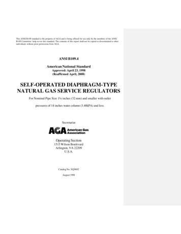
B.DETERMINE WHERE THE TRACK WILL BEINSTALLEDDouble check the orientation of your stair lift.Optional Mounting (Angled View)The chassis box of your stair lift will be marked aseither a Left Hand unit or a Right Hand Unit.Stand at the bottom of the staircase on which you willbe installing the lift. A left hand unit will be traveling upthe left side of the staircase and a right hand unit willbe traveling up the right hand side of the staircase.If the handedness of the unit is consistent with the liftyou ordered, continue the installation. If the handedness is wrong, please contact the authorized sellerfo the unit.Verify there is adequateclearance at the lower landing for the track and seat.Minimum clearance requiredbeyond the bottom step is10" plus the depth of onestep (see Fig. 1).Optional Mounting Side ViewBolt is 3/8” fromend of trackFig.1Door jamb/other obstruction1/4-20NC Bolt10"Depth ofStepIf you will be mounting the track so that it stopsat the bottom step instead of the lowest landing, you MUST drill a hole through the side ofthe track and insert at least a 1/4"-20NC bolt(supplied) on each side of end of the track toact as a mechanical stop in case of completemechanical or electrical failure.63/8" [10mm]1/4"-20NC Bolts
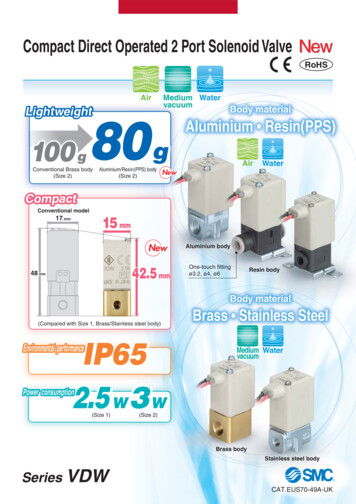
An Introduction to T-BoltsThroughout the installation of the track,you'll be using T-bolts to attach trackbrackets and a grounding bolt.A T-bolt can be a tricky thing if you can'tsee what you're doing, so we've includedthis handy reference guide to walkyou through what should be going onunderneath the track.This is the stair lift Track on its side:This is thebottom of thetrackT-bolts willfit hereGear Rack goesin this channelThe T head ofthe bolt simplydrops into thechannel on thetrack. Once thebolt is turned, theT head catchesin the channneland a bolt can betightend down.See picturesbelow.The T head ofthe bolt must beplaced parallel tothe channel in thetrack. Push it intothe channel andtwist to lock inplace.Your T-Bolts look like this:T-BoltT-Bolt NutThe handy thing about a T bolt is thateven when the track is on the staircase,you can reach to the underside of thetrack, snap the bolt in place and screwit in.Now that the TBolt is locked inthe channel youcan apply the nut.7
C.INSTALL LOWER END CAPSlide the endcap on to the bottom of the trackFeed the charging wire through the top of the trackto the bottom of the track.Note: There is no up or down to the wiring harness. Before putting the charging wire in the track,decide where you will be plugging the stairlift unitinto the wall. Run the wire so that the end of thecharging wire with the extra plug and ring terminalwill be on the floor with the plug (see diagram onpage 9).EndcapFit this ridge into the trackPlug the Spade Connectorof the Charging wire hereFor instance, if you will be plugging the unit into anoutlet on the bottom floor, make sure the end of thecharging wire with the extra plug and ring terminalare exiting the track on the bottom landing.TipOne of theeasiest waysto feed thecharging wirethrough thetrack is to tapethe end ofthe wire to atape measureand feed thetape measurethrough thetrack.Plug the spade connector into the metal plug onthe inside of the end cap as shown below.Track (End View)The dovetail portion ofthe endcap fits into thischannelAny extra wires will tuckinto this channel.If your stairlift will be plugged into the wall at thebottom of the staircase, you will have two extrawires protruding from the lower endcap, one witha ring terminal and one with a Molex plug (seediagram at right). Those other wires will need tobe routed to exit between the track and the endcap and then tuck into the channel on the bottomof the track (see illustration above). Take care tomake sure that the wires are not pinched.NOTE: If the power supply will be on the top landing you may skip this step and the next one, butyou will need to follow them when you install theupper end cap, because you will have the extrawiring at that end of the track.8
The harness is included with enough wire to coverall installations. Most likely, you'll have more wirethan you need. DO NOT CUT THE WIRE. Simplyplace excess wire inside the track.With the wires now routed out of the track you willneed to attach the grounding ring. Insert a T boltin the track, near the end cap. Slide the GroundingRing Terminal (see illustration at right) over the Tnut you just put in. Screw a nut over the T bolt totighten down the grounding ring.Charging WireSpade Connector,attaches to endcapIf your track will not be resting on the lowerlanding, but will be ending on the lowest step,insert a second T bolt and bolt the endcap onfrom the bottom (see below)Underside of trackEndcapT nuts andboltsGroundingWireTrackProvide power to the unit by plugging themolex plug from the track into the matchingplug from the transformer, then plug the A/Ccord into the other end of the transformer.Finally, plug in the A/C cord to the wall.TransformerA/C cordMolex plug coming from trackMolex plug coming from transformerMolex Plugattaches toPower SupplySpadeConnector,attaches toend capD. ASSEMBLE MOUNTING HARDWAREThe track brackets come in 5 pieces: 1 riser,2 feet and 2 covers for the feet. Assemble asillustrated. When installing the T bolts into thetrack bracket, make sure to thread the boltson, but do not tighten yet.T bolts(these will fit intothe track)Nut for cage boltRiserGround Terminalattaches to T boltTrack Foot5/16-18 x ¾"Cage bolts9
E.MOUNT TRACK TO THE STAIRCASETipIt's a good idea to put down a drop cloth duringyour install so when you slide the track around onthe staircase you don't mark up carpet or scratchhardwood stairs.Tread below the top landingTread above a track spliceTread below a track spliceCenter of each section of trackNote: These instructions are for mounting to astandard wood staircase. For installation onhard surface stairs, anchors may be neededand different screws may be required. Consultfloor manufacturer for detailsLay track along staircase. Make sure that: The gear rack is facing the wall The lower end cap is installed The charging wire is oriented correctlyPlace thebrackets onthe stepswhere youwill Once the track is laid on the stairs it will wantto slide down the staircase, so you will needto put something to stop it, a toolbox or someother heavy weight will work well.Position the track in the middle of the staircasewith the underside of the track resting across thestair nosings, and the lower track end cap restingon the lower landing. With the track placed in themiddle of the staircase you'll have adequate roomto reach under and adjust the track bracketsThe track brackets attach to the track withthe supplied T bolts. You will need to place 3brackets per 8' section of track.If you have spliced 2 pieces of track together,you will need to place a track bracket on thestep directly above and the step directly belowthe splice. A typical placement will have onebracket at each of the following postions:1st tread at the bottom of thestair10Use the T nuts to attach the track to thebrackets.TrackT bolts holding trackbracket to trackUnderside view of the track bracket mounted tothe track. This side will be facing the steps.For more specific help with T nuts refer topg. 7Use a wrench to tighten everything up andslide the track over 3½" from the wall.Verify that both the bottom of the track and thetop are 3½" from the wall. If they are not, thestairlift will not travel straight.Note: This distance is needed for clearance of the seatback in the riding and swivelled position.
Attach the track mounting brackets to the staircase.The brackets attach to the stair treads with woodscrews.The bottom of the track should be touching thenose of stairs once the brackets are bolted down.F.INSTALL THE CHASSIS ASSEMBLY INTO THETRACKNOTE: If you will need to change remote frequencieson the call/send remote controls do this PRIORto mounting the chassis on the track. With thechassis close to the wall, it may become difficultto remove the shroud and access the controlboard. Refer to Step C of the Service Informationfor instructions on changing the frequency of theremote control.Cut open the stair lift box, pull out the unitwhich will be attached to a plank of wood.Use the plank to support the unit, andcarefully transport the unit to the top of thestaircase.Track Bracket installed.Do not carry the unit by the plastic shroud!Doing so could cause the unit to come awayfrom the shroud and cause serious injury!Wooden Mounting PlankStair lift ChassisMounting PlatesLoad ToolUnbolt the mounting plates to free the stairlift unit and load tool. There will be two barsprotruding from one end.Track Bracket cover installed.11
TipBefore loading the unit on the track, take thepower wires and lead them through the piece ofstarter track the stair lift is mounted on, that way,they won't fall down into the track.Grip the seat post and gently pull the chassis upthe track, not to move it, but just to take enoughpressure off the retaining bolt. Remove the boltfrom the starter track and gently slide the unitdown the track until the chassis is fully on themounted track and the gears have engaged.Line up the splice bars of the starter track with thetop end of the track bolted to the staircase. Lift theunit and insert the splice bars into the track.Ready To LoadRetaining BoltRemove the starter track.On The TrackInstall the top endcap by attaching the terminal ofthe charging wire to the terminal on the inside ofthe top end cap. Insert (1) T-bolt in each T-slot attop of track, then fasten the end cap to the upperend of the track with nuts provided.12
G.INSTALLING THE FUSEH. TEST RUN THE CHASSISOperate pendant control to verify that the stair liftwill go up and down properly, while holding theseat swivel switch in. The seat swivel switch islocated on the back of the seat post (see illustration below) and the unit will not run if the switchis not pressed in. Normally, the seat on the unitwill acctuate the switch, but because there is noseat, you will need to do this manually.Seat PostRemove the front cover of the stairlift by removingthe
This stair lift Installation and Service Manual has been written to provide clear and precise instructions for proper installation procedures of the Citia BOS stair lift. Please refer to the Owner's Manual for warranty information and operating instructions. The Owner's Manual must be give