Transcription
This is a photographic template – yourphotograph should fit precisely within this rectangle.Arc Flash Hazard MitigationAugust 25, 2015Luaya Halig, PEJudy A. Robinson
Agenda Arc Flash Requirements – NFPA 70E andOSHA NEC Arc Energy Reduction Arc Flash Hazard Mitigation Techniques Arc Resistant Equipment22
This is a photographic template – yourphotograph should fit precisely within this rectangle.Arc Flash RequirementsNFPA 70E 2015OSHA 29 CFR 1910.269August 25, 2015Luaya Halig, P.E.Service Sales Engineer
Outline NFPA 70E 2015 Arc Flash Definition Overview of Arc Flash Requirements Important Changes to Arc Flash in latest Revision Arc Flash PPE Categories vs. Incident EnergyAnalysis Methodology OSHA 29 CFR 1910.269 What are The New Requirements? When is Compliance Due?44
NFPA 70E 201555
Arc Flash Introduction(NFPA70E Article 100)Arc Flash Hazard - A dangerous condition associated with thepossible release of energy caused by an electric arc. An arc flash hazard may exist when energized electricalconductors or circuit parts are exposed or when they are withinequipment in a guarded or enclosed condition, provided aperson is interacting with the equipment in such a manner thatcould cause an electric arc. Under normal operating conditions, enclosed energizedequipment that has been properly installed and maintained isnot likely to pose an arc flash hazard.6
NFPA70E Overview - Article 130.2(A)Work Involving Electrical HazardsAm I required to wear PPE for every taskperformed on electrical equipment?Electrically Safe Working ConditionsNFPA-70E Exceptions1. Additional Hazards or Increased Risk2. Infeasibility3. Less than 50 VoltsNew Exception to the 2014 NFPA-70E4. Normal Operation7
NFPA70E Overview - Article 130.2(A)(4)Work Involving Electrical HazardsNormal operation of electric equipment shall be permittedwhere all of the following conditions are satisfied130.2(A)(4):(1) The equipment is properly installed.(2) The equipment is properly maintained.(3) The equipment doors are closed and secured.(4) All equipment covers are in place and secured.(5) There is no evidence of impending failure.8
Who Does These Changes Affect? Qualified personnel working on electricalequipment. Personnel working near energized electricalequipment.99
New Terms in NFPA-70E Risk: “A combination of the likelihood of occurrence of injury or damageto health and the severity of injury or damage to health that resultsfrom a hazard.” Risk Assessment “An overall process that identifies hazards, estimates the potentialseverity of injury or damage to health, estimates the likelihood ofoccurrence of injury or damage to health, and determines ifprotective measures are required.”1010
NFPA 70E Changes Shock Risk Assessment “.shall determine the voltage to which personnelwill be exposed, the boundary requirements, andthe PPE necessary in order to minimize thepossibility of electric shock to personnel.”1111
NFPA 70E ChangesArticle 130.5 Arc Flash Risk Assessment Is there an arc flash hazard? If so, the riskassessment must contain the following: Appropriate safe-work practices Arc Flash Boundary Appropriate PPE1212
NFPA 70E ChangesArticle 130.5 Arc Flash Risk Assessment Update studies when major modifications orrenovations take place. Study should be reviewedat an interval not to exceed five (5) years. Take into consideration the design and condition ofovercurrent devices.1313
NFPA-70E Article 130.5 (C)Appropriate PPETwo MethodsIncident Energy Analysis Arc Flash PPE Categories Equations / Calculations Tables 130.7(C)(15)(A)(a)/(b),130.7(C)(15)(B), & 130.7(C)(16) PPE Categories 1-41414
Working in a Situation Where an Arc-FlashHazard Exists: Arc-Flash Warning LabelElectrical equipment that are likely to require examination, adjustment, servicingor maintenance while energized shall be field marked with a label containingthe following (Refer to NFPA 70E-2015, Art. 130.5(D)): Nominal systems voltage Arc flash boundary At least one of the following: Available incident energy and the corresponding working distance, or the arcflash PPE category in Table 130.7(C)(15)(A)(b) or Table 130.7(C)(15)(B) forthe equipment, but not both Minimum arc rating of clothing Site-specific level of PPEThe method of calculating and data to support the information for the label shallbe documented.15
Arc Flash Labels1616
Arc-Flash BoundaryAn arc-flash boundary is an approach limit at which aperson would be expected to receive a just curableburn on exposed skin if an arc flash were to occur.If you are required to work within the arc-flashboundary, you are also required to wear arc-ratedgarments.17
Arc Flash Boundary and Limits ofApproachApproach & Arc Flash Boundaries1818
Arc Flash PPE Categories Process Step 1: Refer to Table 130.7(C)(15)(A)(a)This table identifies arc flash hazards based on a listof common tasks.1919
Arc Flash PPE Categories Process Step 2: Refer to Table 130.7(C)(15)(A)(b) for ACEquipment or Table 130.7(C)(15)(B) for DCEquipmentThese tables can be used if associated parameters are met.2020
Arc Flash PPE Categories Process Step 3: Refer to Table 130.7(C)(16) for PersonalProtective Equipment (PPE)2121
Arc Flash PPE Categories Process Step 1: Refer to Table 130.7(C)(15)(A)(a)This table identifies arc flash hazards based on a listof common tasks.2222
Maintenance RequirementsNFPA-70E Article 205.3 Electrical equipment shall be maintained inaccordance with manufacturer’s specificationsand/or industry standards. Improper maintenance may result in increasedopening time of devicesIncreased Incident EnergyPPE may not provide adequate protection2323
OSHA 29 CFR2424
Excerpts from OSHA 29 CFR 1910The final rules for general industry and constructioninclude new and revised provisions on host employers(facility operator) and contractors. training job briefings fall protection work on transmission and distribution lines working in manholes and vaults electrical hazards (including arc flash)2525
Protection from Flames & Electric ArcsOSHA 1910.269 (Appendix E)The employer shall:1. Assess the workplace to identify employees exposedto hazards from flames or from electric arcs.2. Estimate incident energy values.3. Ensure employees wear flame-resistant clothing andPPE with adequate arc ratings that will not melt orignite and continue to burn.2626
Frequently Asked QuestionsOSHA Final RulingWhat Methods are acceptable per OSHA Final Ruling? Below is a table taken from the final rule that illustrates whatmethods OSHA will accept for calculating incident energy.2727
Frequently Asked QuestionsOSHA Final RulingFrom OSHA Final Ruling: OSHA based the determination of the level of PPE required underthe final rule solely on incident heat energy. OSHA’s final ruleseparates the determination of risk (that is, whether an employeeis exposed to hazards posed by electric arcs), as required by finalparagraph (g)(1), from the calculation of incident energy, asrequired by final paragraph (g)(2). Therefore, the Agencyconcludes that NFPA 70E Table methodology, is not areasonable method of estimating incident energy under finalparagraph (g)(2) and, therefore, is not referencing that table inAppendix E in the final rule.2828
When is Arc Flash Compliance Required? No later than January 1, 2015, employers mustestimate the incident heat energy of any electric-archazard to which a worker would be exposed. No later than April 1, 2015, employers generally mustprovide workers exposed to hazards from electric arcswith protective clothing and other protective equipmentwith an arc rating greater than or equal to theestimated heat energy.2929
Frequently Asked QuestionsOSHA Final RulingQuestion: I have already completed an arc flashstudy assessment for my facility. Do I need rerunthe analysis per new OSHA regulations?Answer: Maybe? As long as the incident energy analysis was completed accordingto the guidelines in 1910.269 Appendix E. NFPA 70E requires that arc flash study assessments be updatedat a minimum of every 5 years or when major changes areimplemented to the power system.3030
Frequently Asked QuestionsOSHA Final RulingQuestion: What kinds of fines does OSHAimpose for violations?Answer: OSHA violations are defined as: Other than serious: Proposed penalty ( 7,000 maximum) per violation Serious: Mandatory penalty ( 7,000 maximum) per violation Willful: Minimum penalty of 5,000 up to 70,000 per violation If an employer is convicted of a willful violation of a standard that hasresulted in the death of an employee, the offense is punishable by acourt-imposed fine or by imprisonment for up to six months, or both. Afine of up to 250,000 for an individual, or 500,000 for a corporation,may be imposed for a criminal conviction.3131
This is a photographic template – yourphotograph should fit precisely within this rectangle.National Electrical CodeArc Energy Reduction
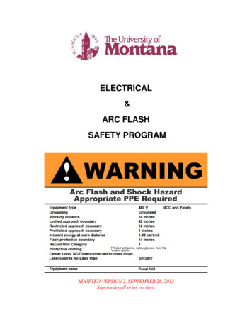
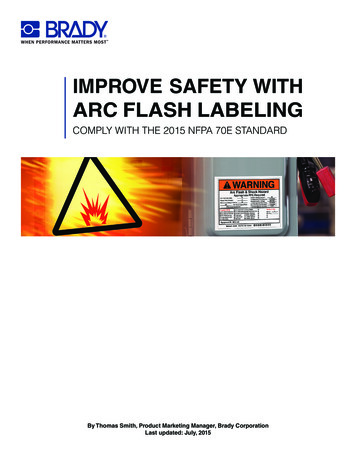
Circuit breaker basicsThe Trip Curve A trip curve is plotted Time vs.CurrentThe curve tells the trip timesfor various levels of currentMinimum and maximumclearing times1000100MaximumTime (Seconds) Clearing10A Breaker Trips1.0At Some TimeBetween These t (Amps)3333
Overload ExampleContinuous Current1000Became An OvercurrentMax Clearing Time 500Seconds or100Min Clearing Time 50 Seconds or 0.83 Minutes10Time (Seconds)Overload currents cantake quite some timeto clear 8.33 Minutes1.00.10.010.0050.51020200Current34 (Amps)100034
Short Circuit Example1000 Calculated maximum faultcurrents may be quite highresulting in very fasttripping times Maximum fault current isbased on a bolted faultcondition10Time (Seconds) This fault current is in theinstantaneous region of thecircuit breaker100Fault Current1.00.1Max ClearingTime0.010.0050.51020200Current35 (Amps)100035
Bolted Fault vs. Arcing FaultBolted FaultArcing FaultSystems must be designed3636
Arcing Fault Example1000 Arcing currents arecalculated based on the3-Phase bolted faultIEEE 1584: “IEEE Guidefor Performing Arc-FlashHazard Calculations”Arcing currents are oftencleared in the overloadrange of the circuitbreaker100Arcing Fault Current10Time (Seconds) 38 % Of BoltedMax Clearing Time1.0Min Clearing Time0.10.010.0050.51020200Current37 (Amps)100037
Pre - NEC 2011 LanguageNFPA 70Prior To 240.87110.16 Arc-FlashHazard WarningThe only installationrequirement specific tothe arc flash hazard110.16 Arc-Flash Hazard Warning. Electrical equipment,such as switchboards, panelboards, industrial controlpanels, meter socket enclosures, and motor controlcenters, that are in other than dwelling units, and arelikely to require examination, adjustment, servicing, ormaintenance while energized shall be field marked towarn qualified persons of potential electric arc flashhazards. The marking shall be located so as to be clearlyvisible to qualified persons before examination,adjustment, servicing, or maintenance of the equipment.Informational Note No. 1: NFPA 70E-2009, Standard forElectrical Safety in the Workplace, provides assistance indetermining severity of potential exposure, planning safework practices, and selecting personal protectiveequipment.Informational Note No. 2: ANSI Z535.4-1998, ProductSafety Signs and Labels, provides guidelines for thedesign of safety signs and labels for application toproducts.3838
2011 NEC Addition240.87 Noninstantaneous Trip. Where a circuit breaker is used without aninstantaneous trip, documentation shall be available to those authorized todesign, install, operate, or inspect the installation as to the location of thecircuit breaker(s).Where a circuit breaker is utilized without an instantaneous trip, one of thefollowing or approved equivalent means shall be provided:(1) Zone-selective interlocking(2) Differential relaying(3) Energy-reducing maintenance switching with local status indicatorInformational Note: An energy-reducing maintenance switch allows a worker to set a circuitbreaker trip unit to “no intentional delay” to reduce the clearing time while the worker is workingwithin an arc-flash boundary as defined in NFPA 70E-2009, Standard for Electrical Safety in theWorkplace, and then to set the trip unit back to a normal setting after the potentially hazardouswork is complete.3939
NEC 2014 Section 240.87240.87 Arc Energy Reduction. Where the highest continuous current trip setting for whichthe actual overcurrent device installed in a circuit breaker is rated or can be adjusted is 1,200amperes or higher then (A) and (B) shall apply.(A) Documentation. Documentation shall be available to those authorized to design, install,operate, or inspect the installation as to the location of the circuit breaker(s).(B) Method to Reduce Clearing Time. One of the following or approved equivalent meansshall be provided:(1) Zone-selective interlocking or(2) Differential relaying or(3) Energy-reducing maintenance switching with local status indicator or(4) Energy-reducing active arc flash mitigation system or(5) An approved equivalent meansA historical code changeOne of the most important eaps in arc flash safety for the electrical industry4040
200JKLMNRFrameFrameFrameFrameFrameFrameFrame200A – 6000AF(800A – 2500A)400(70A – 250A)600(15A – 100A)800(10A – 225A)1,000(70A – 400A)2,000(70A – 600A)4,000(300A – 800A)6,000(400A – 1200A)Current circuit breaker ranges on the market9010MiniatureNot impacted by requirementPCB1200 amps and aboveagreed upon byconsensus of code41 making panel 1041
NEC 2014’s Section 240.87(B) Method to Reduce Clearing Time. One of the following orapproved equivalent means shall be provided:(1) Zone-selective interlocking or(2) Differential relaying or(3) Energy-reducing maintenance switching with local statusindicator or(4) Energy-reducing active arc flash mitigation system or(5) An approved equivalent means4242
(1) Zone selective interlockingCase 1Case 2 Communication betweencircuit breakers Acts to reduce trip times Helps reduce arc flash energyIscIscCase 1: Both breakers see fault Upstream breaker waits as designedCase 2: Only upstream breaker sees fault No input from downstream breaker Trip as fast as possible4343
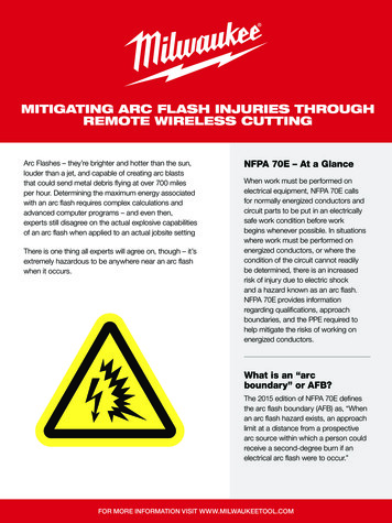
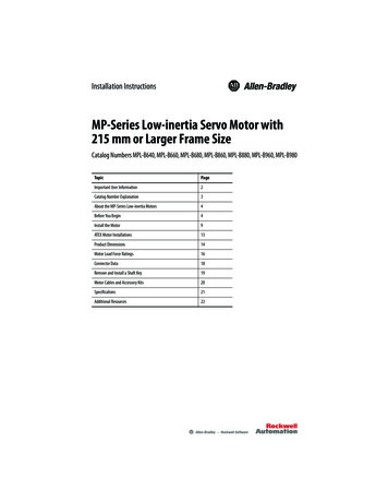
Zone Selective Interlock ExampleM1SD 0.5S35kA fault currentF1F2SD 0.3SWithout ZSI 0.5 S:43.7 Cal/cm2XF3SD 0.3SSD 0.3SWith ZSI 0.08 S:7.0 Cal/cm2What do we put on the Arc Flash label?4444
Zone Selective Interlocking – Pros and ConsPros Standard feature on most Power Circuit Breaker and Insulated Case BreakerTrip Units Available on many Molded Case Breaker Trip Units Inexpensive where electronic trip units are already specified Reduces clearing time for short circuits and ground faultCons Requires multiple (at least 2) layers of electronic trip breakers Requires inter-wiring between breakers to work Difficult to apply outside of an assembly Not recommended to mix manufacturers Gets more complicated with complex systems (M-T-M, etc.) Slower than instantaneous trip due to communication lag Probably won’t reduce PPE requirements. Not applicable in certain assemblies (MCC, Meter Center) Difficult to Test4545
NEC 2014’s Section 240.87(B) Method to Reduce Clearing Time. One of the following orapproved equivalent means shall be provided:(1) Zone-selective interlocking or(2) Differential relaying or(3) Energy-reducing maintenance switching with local statusindicator or(4) Energy-reducing active arc flash mitigation system or(5) An approved equivalent means4646
(2) Differential relayingDifferential Relay Similar to zone selectiveinterlocking Recognizes faults within the CurrentTransformerszone of protection Acts to reduce arc flashZone of ProtectionNot a practical solution in LV equipment due to space limitations.4747
NEC 2014’s Section 240.87(B) Method to Reduce Clearing Time. One of the following orapproved equivalent means shall be provided:(1) Zone-selective interlocking or(2) Differential relaying or(3) Energy-reducing maintenance switching with localstatus indicator or(4) Energy-reducing active arc flash mitigation system or(5) An approved equivalent means4848
(3) Energy-reducing maintenanceswitching with local status indicator Manually or automatically enables aninstantaneous pickupTrip times may vary betweenmanufacturers Some may be same asinstantaneous Some may be faster thaninstantaneous Reduces arc energy to downstreamequipment/personnelLimits energy available duringmaintenance4949
MCCB310 Maintenance ModeArcing fault test apparatus(Click video to view – no sound)Arc chamber and calorimeter5050
MCCB1200A Interrupting Devices (9kA @ 480V)Breaker w/ InstantaneousBreaker w/ Maintenance Mode(Click videos to view)5151
MCCB1200A Comparison Data Table (9kA @ 480V)DeviceNG w/NG w/InstantaneousMaint. ModePeak Fault Current (kA)14.814.5Time to Clear (ms)45.918.2[improvement vs.Instantaneous]Arcflash Energy (Cal/cm2)[improvement vs. Instantaneous]60%1.630.4175%5252
Arc Flash Reduction Maintenance System –Pros and ConsPros Available on many Power, Insulated Case and Molded CaseBreaker electronic trip units Inexpensive where electronic trip units are already specified Can be applied only on the breakers required (no inter-wiring) Can be provided in different types of assemblies Extremely fast acting – faster than instantaneous for somemanufacturers Reduces both the trip setting and the trip time Easy to testCons Requires user interaction to provide protection Does not reduce trip time for ground faults5353
NEC 2014’s Section 240.87(B) Method to Reduce Clearing Time. One of the following orapproved equivalent means shall be provided:(1) Zone-selective interlocking or(2) Differential relaying or(3) Energy-reducing maintenance switching with local statusindicator or(4) Energy-reducing active arc flash mitigation system or(5) An approved equivalent means5454
(4) Energy-reducing active arc flashmitigation system When activated, this technologycontinuously monitors current andvoltage to identify an arc flash When an arc flash occurs, the arc isautomatically dealt with, withoutchanges to the circuit breakerInformational Note No. 2: An energy-reducing active arc flash mitigation system helps inreducing arcing duration in the electrical distribution system. No change in circuit breaker or thesettings of other devices is required during maintenance when a worker is working within an arcflash boundary as defined in NFPA 70E-2012, Standard for Electrical Safety in the Workplace.5555
NEC 2014’s Section 240.87(B) Method to Reduce Clearing Time. One of the following orapproved equivalent means shall be provided:(1) Zone-selective interlocking or(2) Differential relaying or(3) Energy-reducing maintenance switching with local statusindicator or(4) Energy-reducing active arc flash mitigation system or(5) An approved equivalent means5656
(5) An approved equivalent meansConfirm approved equivalent means byrequesting a copy of arc flash study1000Compare with one of the four listed methodsTime (Seconds)100Confirm approved equivalent means byrequesting a copy of arc flash studyArcing Fault CurrentA % Of Bolted101.00.1Max Clearing Time0.010.0050.510202001000Current (Amps)5757
(5) An approved equivalent meansConfirm any approved equivalent meansby comparing arc flash calculated values Calculated arc flash values based on any one ofthe listed options Calculated arc flash values when applying thetechnology which is seeking to be an approvedequivalentSubject to AHJ Approval5858
Questions and Discussion Enforcement? Handbook?5959
This is a photographic template – yourphotograph should fit precisely within this rectangle.Arc Flash Hazard MitigationDesign Considerations for New ProjectsOptions for Existing Facilities
NFPA 70E Summary The intent of NFPA 70E regarding arc flash is toprovide guidelines which will limit injury to theonset of second degree burns (1.2 cal/cm2).Note: The heat reaching the skin of the worker is dependentprimarily upon: Power of the arc at the arc location Distance of the worker to the arc Time duration of the arc exposure6161
SOLUTIONS THAT REDUCE ARC FLASHINJURIES and DAMAGEDirect: Reduce Available Fault Current Faster Clearing Time Move People Further AwayIndirect: Label Equipment & Train Personnel Minimize Risk with Good Safety Practices Redirect Blast Energy6262
Reduce Available Fault Current(Reduce Incident Energy)6363
Practical Non-PPE Arc Flash SolutionsReducing the Short Circuit Current: Current Limiting Reactors Design using more smaller transformers instead of fewerlarger transformers Increasing cable lengths Specifying higher impedance transformers Open Transition TransfersBeware:Reducing the short circuit current by too much can increase theduration of the arc, causing the incident energy to increase!6464
Faster Clearing Time6565
Design Considerations for New Projects –Faster Clearing Time Meet the requirements of 240.87(1) Zone-selective interlocking or(2) Differential relaying or(3) Energy-reducing maintenance switching with localstatus indicator or(4) Energy-reducing active arc flash mitigation system It’s OK to employ more than one of the aboveand/or use where not required by code.6666
Practical Methods for Reducing Arc FlashHazardsMultiple Settings Groups Similar to LV maintenanceswitch, only for MVapplications Used to reduce the trip delayof medium-voltage relays whilemaintenance is beingperformed on equipment. Requires relay with multiplesettings groups capability6767
Options for Existing Facilities – FasterClearing Time Zone Selective Interlocking Energy Reducing Maintenance Switches Substation Retrofits6868
Options for Existing Facilities – FasterClearing Time Energy Reducing Maintenance Switches Maintenance Switch Retrofits Trip Unit Retrofits Switchgear Retrofills6969
Arcflash Reduction Maintenance System - Retrofitof LV - PCBs Door MountedComponents Breaker TRIPSwitchBatteryArcflash Reduction Maint System7070
Retro Fill Example – with “ARMS” 2000-Amp FusesSupplying 480V GlassFurnaces Incident Energy was61 Cal / PPELevel Danger Retro-filled Fuses withBreakers 35 cal with trip Unit 6 cal with New Breaker Built-in ARMS7171
Low Voltage Air circuit breaker Replacement(LVAR)7272
Technologies/Upgrades to Reduce Arc-Flash Hazard2000kVA Unit Substation – Addition of 50/51 Overcurrent RelayDesign Limitations Secondary busfault protection Secondary busoverloadprotectionNEC Article 240.21(C)2 Allows unprotected secondary conductorTransformer Secondary Conductors not over 3 meters long7373
Technologies/Upgrades to Reduce Arc-Flash HazardPower Distribution technologies to Reduce Arc-Flash HazardsSubstation PrimaryFusible SwitchSubstation Primary Switchand Vacuum Circuit Breaker7474
Substation Primary Switch and VacuumCircuit Breaker Combines the protection of a powerbreaker with the visible disconnect of aload interrupter switch. CT’s on Primary Side Connect toProtective Relay for TransformerProtection CT’s on Secondary Side Connect toRelay for Switchgear Line SideProtection During normal operating conditions,standard system coordination ismaintained Relays can include the Arc FlashReduction Maintenance system thatlowers the arcing energy for anentire Unit Substation during downstream maintenance. .50/5150N/51N7575
Move People Further Away7676
Remote Racking7777
Universal Racking DevicesVS.7878
Equipment-Specific Remote Racking –Medium Voltage Switchgear ExampleIntegral Racking – Motorized Remote Racking Integral motor is part of thebreaker cellRacking of breakers andauxiliaries (CPT, VT)7979
Equipment-Specific Remote Racking –Low Voltage Switchgear Example Pendant Controlled with Enable Buttonfor Safety Allows Racking & Operation (Open /Close) Mounts to Breaker w/o Additional Door orBreaker Modifications Required Position Indicating Lights8080
Remote Racking of MCC Buckets Some manufacturers offera draw-out MCC bucket A remote operator can beused to rack the MCCstabs on and off the busStabsExtendedStabsWithdrawn8181
Remote Switching8282
Example of Custom Remote Switching PanelMarshalling panel individual controls for mains,tie and all feeders in a switchgear line-up.Close-up of individual breaker controls:Open-Close-Trip plus PBs to connectdisconnect and lights indicatingConnected-Test-Disconnected8383
Touchscreen “Dashboard”8484
Avoid Opening Enclosure Doors Infrared ScanningWindows for LV/MVAssemblies8585
SOLUTIONS THAT REDUCE ARC FLASHINJURIES and DAMAGEDirect: Reduce Available Fault Current Faster Clearing Time Move People Further AwayIndirect: Label Equipment & Train Personnel Minimize Risk with Good Safety Practices Redirect Blast Energy8686
This is a photographic template – yourphotograph should fit precisely within this rectangle.Redirect Blast EnergyArc Resistant Equipment
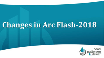
WHY ARC RESISTANT EQUIPMENT? Bolted fault No arc Resistance fault Severe arc8888
WHY ARC RESISTANT EQUIPMENT? Arcing occurs when there is impedancebetween a phase and ground or betweenphase & phase Arc faults release large amounts energy in theform of heat, light and pressure The arc is generating heat at temperatures upto 35,000 F Materials are vaporized8989
WHY ARC RESISTANT EQUIPMENT? Arc is maintained through vapor of thevaporized material which is highly conductive Arc faults release large amounts in the form ofheat, light and pressure If arc fault occurs within the equipment, arcmaterials and an overpressure wave will exitthe assembly9090
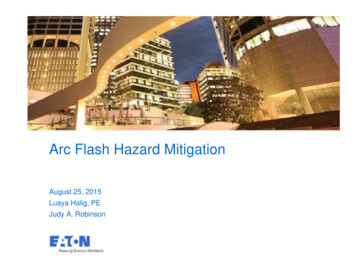
WHY ARC RESISTANT EQUIPMENT?35,000 FMolten MetalPressure WavesSound WavesShrapnelCopper Vapor:Solid to VaporExpands by67,000 timesHot Air-Rapid ExpansionIntense Light9191
Arc Flash Concerns To put Arc Flash Concerns into perspective Temperatures Arc temperatures35,000ºF Surface of the Sun9,000 ºF Skin Temperature for a curable burn (2nd Degree) Skin Temperature causing cell death176 ºF205 ºF Requires skin grafts Pressure Wave Copper vapor expands 67,000 in volume 1” of copper expands to the size of a refrigerator929292
Arc Flash Concerns To put Arc Flash Concerns into perspective Sound Can exceed 145dB @ 2 feet 105dB is jet engine dB is on a logarithmic scale ( doubles every 10dB increase) Vision Flash of light can create serious and permanent loss of vision939393
WHY ARC RESISTANT EQUIPMENT? Conventional short circuit fault testing isperformed on the following basis Tests are based on bolted faults Interrupting & switching devices are tested ascomponents and are not required to be installed inthe assembly Dummy breakers can be used for temperature risetests No consideration is taken for arcing faults within theequipment being tested9494
WHY ARC RESISTANT EQUIPMENT? To protect personnel from arc materialsexpelled from equipment. During work around energized equipment House-keeping Working on other de-energized equipment in vicinity While opening/closing equipment While racking equipment in/out of compartment Changing settings (if available with door closed) Trouble-shooting control compartment (if tested to1B or 2B)9595
WHY ARC RESISTANT EQUIPMENT? Lowers PPE requirement per NFPA 70E forracking or operating equipment with doors &panels closed Change in the 2009 edition Previous editions gave no relief Hazard/Risk Category reduced to 0 – ReferenceTable 130.7(C)(9)9696
WHAT DOESN’T IT DO? Lower Incident Energy Values Offer protection to operatorwith any door opened or panelremoved (except 2B instrumentcompartments) Lower the PPE requirementwhen working on energizedequipment with doors open Prevent or preclude damage tothe equipment9797
TYPES OF ARC RESISTANTEQUIPMENT Type 1 – Arc resistant at front of equipment only Type 2 – Arc resistant at front, sides, and rear of equipment Suffix B – Arc resistant with doors open on compartmentsdesignated as low voltage control or instrumentationcompartments Suffix C – Isolation between adjacent compartments Suffix D – Applies only to Type 1 and adds protection onadditional sides9898
TYPES OF ARC RESISTANTEQUIPMENT Type 1 Not many products available with this rating Usually not specified particularly for rear accessibleequipment Testing very expensive and not much demand forNOthis ONFRONTFLASHPROTECTION9999
TYPES OF ARC RESISTANTEQUIPMENT Type 2 Commercially available Typically NFLASHPROTECTIONFRONTFLASHPROTECTION100100
TYPES OF ARC RESISTANTEQUIPMENT Type 1B & 2B Allows access to the rear of meters, relays, terminalblocks for troubleshooting while equipment isenergized Standard does not imply that equipment can beoperated continuously with door open101101
TYPES OF ARC RESISTANTEQUIPMENT Type 1C & 2C Limited availability Costly Couples personnel protection with internal arcpropagation for equipment Isolation between adjacent units from effects ofinternal arcing fault May also require isolation between individual circuitsin same vertical structure where two high designused May restrict construction to single high design102102
TYPES OF ARC RESISTANTEQUIPMENT Types 1BC & 2BC Includes features for both suffixes Type 1D Limited availability Must include additional characters to indicate whichadditional sides are protected SR – Side Right SL – Side Left R – Rear Due to cost of testing, might as well test to Type 2103103
RATINGS – ARCING CURRENT Standard does not list desired ratings Manufacturer can chose ratings and test accordingly Ratings are typically 30kA, 40kA, 50kA, 63kA for MV Ratings are typically 85kA & 100kA fo
New Exception to the 2014 NFPA-70E 4. Normal Operation. 8 NFPA70E Overview - Article 130.2(A)(4) Work Involving Electrical Hazards Normal operation of electric equipment shall be permitted where all of the following conditions are satisfied . National Electrical Code Arc Energy Reduction. 33 33 A trip curve is plotted Time vs.