Transcription
Module4www.learnabout-electronics.orgField Effect TransistorsModule 4.1Junction Field Effect TransistorsField Effect TransistorsAlthough there are lots of confusing names for fieldeffect transistors (FETs) there are basically two maintypes:What you ll learn in Module 4Section 4.1 Field Effect Transistors. FETs JFETs, JUGFETs, and IGFETS The JFET. Diffusion JFET Construction. Planar JFET Construction. JFET Circuit Symbols.1. The reverse biased PN junction types, the JFET orJunction FET, (also called the JUGFET or JunctionUnipolar Gate FET).Section 4.2 How a JFET Works. Operation Below Pinch Off. Operation Above Pinch Off. JFET Output Characteristic. JFET Transfer Characteristic. JFET Video.2. The insulated gate FET devices (IGFET).All FETs can be called UNIPOLAR devices becausethe charge carriers that carry the current through thedevice are all of the same type i.e. either holes orelectrons, but not both. This distinguishes FETs fromthe bipolar devices in which both holes and electronsare responsible for current flow in any one device.Section 4.3 The Enhancement Mode MOSFET. The IGFET (Insulated Gate FET). MOSFET(IGFET) Construction. MOSFET(IGFET) Operation. MOSFET (IGFET) Circuit Symbols. Handling Precautions for MOSFETSThe JFETThis was the earliest FET device available. It is avoltage-controlled device in which current flowsfrom the SOURCE terminal (equivalent to theemitter in a bipolar transistor) to the DRAIN(equivalent to the collector). A voltage appliedbetween the source terminal and a GATE terminal(equivalent to the base) is used to control the source drain current. The main difference between a JFETand a bipolar transistor is that in a JFET no gatecurrent flows, the current through the device iscontrolled by an electric field, hence "Field effecttransistor". The JFET construction and circuitsymbols are shown in Figures 1, 2 and 3.Section 4.4 The Depletion Mode MOSFET. Depletion Mode MOSFET Operation. MOSFE (IGFET) Circuit Symbols. Applications of MOSFETS High Power MOSFETSSection 4.5 Power MOSFETs. MOSFET Calculations. Choosing a MOSFETSection 4.6 MOSFET Switches. Design and Build typical MOSFET SwitchCircuits.Section 4.7 FET Quiz. Check your understanding of Field EffectTransistors.SEMICONDUCTORS 3.PDF1 E. COATES 2016
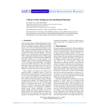
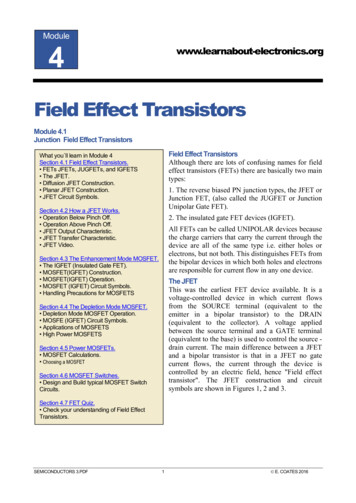
www.learnabout-electronics.orgSemiconductors Module 4 Field Effect TransistorsJFET ConstructionThe construction of JFETs can be theoretically quite simple, but in reality difficult, requiring verypure materials and clean room techniques. JFETs are made in different forms, some being made asdiscrete (single) components and others, using planar technology as integrated circuits.Fig. 4.1.1 shows the (theoretically) simplest formof construction for a Junction FET (JFET) usingdiffusion techniques. It uses a small slab of N typesemiconductor into which are infused two P typeareas to form the Gate. Current in the form ofelectrons flows through the device from source todrain along the N type silicon channel. As onlyone type of charge carrier (electrons) carry currentin N channel JFETs, these transistors are alsocalled "Unipolar" devices.Fig. 4.1.2 shows the cross section of a N channelplanar Junction FET (JFET) The load currentflows through the device from source to drainalong a channel made of N type silicon. In theplanar device the second part of the gate isformed by the P type substrate.JFET Circuit SymbolsP channel JFETs are also available and the principleof operation is the same as the N channel typedescribed here, but polarities of the voltages are ofcourse reversed, and the charge carriers are holes.Notice in the JFET circuit symbols shown in Fig.4.1.3 that the arrowhead on the gate connectionalways points towards the negative connection,indicating the polarity (either P or N channel) of thechannel.SEMICONDUCTORS MODULE 4 PDF2 E. COATES 2020
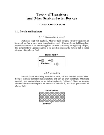
www.learnabout-electronics.orgSemiconductors Module 4 Field Effect TransistorsModule 4.2How a JFET WorksWhat you’ll learn in Module 4 Operation Below Pinch Off. Operation Above Pinch Off. JFET Output Characteristic.The JFET is a Voltage Controlled Transistor.The JFET is a voltage controlled transistor that has two distinctareas of operation depending on the whether the voltageapplied to the Source and Drain terminals is greater or less thatthe transistor's Pinch-Off VoltageThe Pinch Off VoltageThe Pinch-Off value of the JFET refers to the voltage applied JFET Transfer Characteristic.between Drain and Source (with the Gate voltage at zero volts)at which maximum current flows. Operating with the JFET Video.Drain/Source voltage below this value is classed is the "OhmicRegion" as the JFET will act rather like a resistor. Operating with the Drain Source voltage abovePinch Off is known as the "Saturation Region" as the JFET is acting like a saturated transistor; thatis any increase in voltage does not produce a relative increase in current.Operation Below Pinch OffIn the planar construction Nchannel JFET shown in Fig.4.2.1, the N channel issandwiched between two Ptype regions (the gate and thesubstrate) that are connectedtogether and are at 0V. Thisforms the gate. The N typechannel is connected to thesource and drain terminals viamore heavily doped N typeregions. The drain is connected to a positive supply, and the source to zero volts. N type siliconhas a lower resistivity than N type. This gives it a lower resistance, increasing conduction andreducing the effect of placing standard N type silicon next to the aluminium connector, whichbecause aluminium is a tri-valent material, having three valence electrons whilst silicon has four,would tend to create an unwanted junction, similar in effect to a PN junction at this point.The P type gate is at 0V and is therefore negatively biased compared to the channel, which has apotential gradient on it, as one end is connected to 0 volts (the source), and the other end to apositive voltage (the drain). Any point on the channel (apart from the extreme end near the sourceterminal) must therefore be more positive than the gate. Therefore the two PN junctions formedbetween the N type conducting channel and the P type areas of the gate/substrate are both reversebiased, and so have a depletion layer that extends into the channel as shown in Fig. 4.2.1.The shape of the depletion layer is not symmetrical, as can be seen from Fig. 4.2.1. It is generallythicker towards the drain end of the channel, because the voltage on the drain is more positive thanthat on the source due to the voltage gradient that exists along the channel. This causes a largerpotential across the junctions nearer the drain, and so a thickening of the depletion layer. The effectbecomes more marked when the voltage between drain and source is greater than about 1 volt or so.SEMICONDUCTORS MODULE 4 PDF3 E. COATES 2020
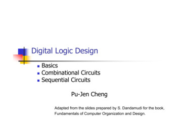
www.learnabout-electronics.orgSemiconductors Module 4 Field Effect TransistorsOperation Above "Pinch Off"When a voltage is applied betweendrain and source (VDS) currentflows and the silicon channel actsrather like a conventional resistor(The Ohmic Region). Now if VDSis increased (with VGS held atzero volts) towards what is calledthe pinch off value VP, the draincurrent ID also at first, increases.The transistor is working in the"ohmic region" as shown in Fig.4.2.1.However as drain source voltage VDS increases, the depletion layers at the gate junctions are alsobecoming thicker and so narrowing the N type channel available for conduction. There comes apoint, (Pinch Off) where the conducting channel has become narrow enough to cancel out the effectof current increasing with the applied voltage VDS as shown in fig 4.2.2. Above this (Pinch Off)point there is little further increase in drain current and the transistor is said to operating in the"Saturation Region".However, if the JFET is biased with VDS at Pinch Off voltage (VP) a small change in VGS can beused to control the current through the source-drain channel from zero current to its maximum(saturated)value .JFET CharacteristicsThis type of operation is shown in thefairly flat top to the outputcharacteristics shown in Fig 4.2.3.Notice that each curve is drawn for aparticular value of negative voltagebetween gate and source, and thatwhen sufficient reverse bias is appliedto the gate (e.g. more than -2.5V, thelowest value on the graph) the draincurrent ceases completely.In the JFET output characteristicsshown in Fig. 4.2.3, the Drain currentID increases in a linear manner (like aresistor) at values of Gate/Sourcevoltage (VGS) below pinch off (The Ohmic Region), but above VP (The Saturation Region) showsvery little change, and the curves are very nearly horizontal at voltages greater than the pinch offvoltage (VP). Almost all of the expected increase in current, due to the increase in voltage betweenSource and Drain (VDS), is offset by the narrowing of the conducting channel due to the growingdepletion layers.SEMICONDUCTORS MODULE 4 PDF4 E. COATES 2020
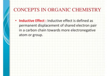
www.learnabout-electronics.orgSemiconductors Module 4 Field Effect TransistorsThe tranconductance characteristic for aJFET, which shows the change in Draincurrent (ID) for a given change in GateSource voltage (VGS), is shown in Fig4.2.4. Because the JFET input (theGate) is voltage operated, the gain ofthe transistor cannot be called currentgain, as with bipolar transistors. Thedrain current is controlled by the GateSource voltage, so the graph showsmilli-amperes per volt (mA / V), and ascurrent divided by Voltage (I/V) isCONDUCTANCE (the inverse of resistance (V/I) the slope of this graph (the gain of the device) iscalled the FORWARD or MUTUAL TRANSCONDUCTANCE, which has the symbol gm.Therefore the higher the value of gm the greater the amplification.Notice that VGS is always shown as being negative; in reality it may be zero or slightly above zero,but the gate is always more negative than the N type channel between source and drain. Note alsothat the slope of the curve in the transfer characteristic is less steep than that of the MutualConductance characteristic for a typical bipolar transistor (compare Fig. 4.2.4 and Fig. 3.5.4 on theBipolar Transistors Current Gain page). This means that a JFET will have a lower gain than that ofa bipolar transistor.This disadvantage is offset by the advantage of having an extremely high input resistance. A typicalinput resistance for a JFET would be in the region of 1 x 10¹⁰ ohms (10,000 Megohms!) comparedwith 2K to 3K Ohms for a bipolar device.This makes the JFET ideal for applications where the circuit or device driving the JFET amplifiercannot supply any appreciable current, an example being the Electret microphone, which uses aFET within the microphone to amplify the tiny voltage variations appearing across the vibratingdiaphragm element.Another feature of the JFET that makes it more suited to very high frequency use than bipolartransistors, is the absence of junctions in the JFET conducting channel. In a bipolar transistor twoPN junctions forming tiny capacitances, exist between base and emitter, and base and collector, dueto the PN junctions. These capacitances will limit high frequency performance, as they providenegative feedback paths at high frequencies. Because the JFET is in effect just a slab of siliconbetween Source and Drain, the stray capacitances that exist in bipolar devices are absent, so highfrequency performance is improved, making JFETs usable even at hundreds of MHz.Download a datasheet for a typical N Channel JFET from On SemiconductorVideo is available at fet 02.phpSEMICONDUCTORS MODULE 4 PDF5 E. COATES 2020
www.learnabout-electronics.orgSemiconductors Module 4 Field Effect TransistorsModule 4.3Enhancement Mode MOSFETs.The Insulated Gate FET (IGFET).The Metal Oxide Silicon FET (MOSFET) or MetalOxide Silicon Transistor (M.O.S.T.) has an evenhigher input resistance (typically 1012 to 1015 ohms)than that of the JFET. In the MOSFET device thegate is completely insulated from the rest of thetransistor by a very thin layer of metal oxide (Silicondioxide SiO2). Hence the general name applied to anydevice of this type, is the IGFET or Insulated GateFET.What you’ll learn in Module 4Section 4.3 The Enhancement Mode MOSFET. The IGFET (Insulated Gate FET). MOSFET(IGFET) Construction. MOSFET(IGFET) Operation. MOSFET (IGFET) Circuit Symbols. Handling Precautions for MOSFETSPlanar Technology.There are several ways in which an insulated gate transistor may be constructed. All the methodsused however, make use of planar technology in which the various parts of the device are laid downas planes or layers on the upper surface of a "SUBSTRATE" in a similar way to that shown on thePlanar Transistors page in the BJT section.The layers are laid down one by one, by diffusing various semiconductor materials with suitabledoping levels, as well as layers of insulation into the surface of the device, under carefullycontrolled conditions at high temperatures. Parts of a layer may be removed by etching, usingphotographic masks to make the required pattern of the electrodes etc. before the next layer isadded. The insulating layers are made by laying down very thin layers of silicon dioxide andconductors are created by evaporating a metal, such as aluminium on to the surface. The transistorsproduced in this way have a much higher quality than is possible using other methods, and manytransistors can be produced at one time on a single slice of silicon, before the silicon slice is cut upinto individual transistors or integrated circuits.MOSFET (IGFET) Construction.The basic construction of a MOSFETis shown in Fig. 4.3.1. A body orsubstrate of P type silicon is used, thentwo heavily doped N type regions arediffused into the upper surface, to forma pair of closely spaced strips.A very thin (about 10-4 mm) layer ofsilicon dioxide is then evaporatedonto the top surface forming aninsulating layer. Parts of this layerare then etched away above the N type regions using a photographicmask to leave these regionsuncovered. On top of the insulatinglayer, between the two N typeregions, a layer of aluminium isdeposited. This acts as the GATEelectrode. Metal contacts are also deposited on the N type regions, which act as the SOURCE andDRAIN connectors.SEMICONDUCTORS MODULE 4 PDF6 E. COATES 2020
www.learnabout-electronics.orgSemiconductors Module 4 Field Effect TransistorsMOSFET (IGFET) Operation.The gate has a voltage applied to it that makes it positive with respect to the source. This causesholes in the P type layer close to the silicon dioxide layer beneath the gate to be repelled down intothe P type substrate, and at the same time this positive potential on the gate attracts free electronsfrom the surrounding substrate material. These free electrons form a thin layer of charge carriersbeneath the gate electrode (they can't reach the gate because of the insulating silicon dioxide layer)bridging the gap between the heavily doped source and drain areas. This layer is sometimes calledan "inversion layer" because applying the gate voltage has caused the P type material immediatelyunder the gate to firstly become "intrinsic" (with hardly any charge carriers) and then an N typelayer within the P type substrate.Any further increase in the gate voltage attracts more charge carriers into the inversion layer, soreducing its resistance, and increasing current flow between source and drain. Reducing the gatesource voltage reduces current flow. When the power is switched off, the area beneath the gatereverts to P type once more.As well as the type described above, devices having N type substrates and P type (inversion layer)channels are also available. Operation is identical, but of course the polarity of the gate voltage isreversed.This method of operation is called "ENHANCEMENT MODE" as the application of gate sourcevoltage makes a conducting channel "grow"; therefore it enhances the channel. Other devices areavailable in which the application of a bias voltage reduces or "depletes" the conducting channel.These are described on the Depletion Mode MOSFET page.Handling Precautions.In operation, although the gate has a voltage applied to it, no gate current flows because of thesilicon dioxide layer beneath the gate terminal. One well known problem exists regarding this layerhowever. Although silicon dioxide is an excellent insulator, the layer used on a MOSFET isextremely thin, and therefore can be permanently damaged if a high voltage is applied across it. Itwill break down just as any other insulator will. Because it is so very thin, it does not need veryhigh voltages to cause total breakdown, and as the gate has such a very high resistance, any voltagepresent will not be reduced by current flow.Therefore voltages due to static electricity, which are present all the time in almost anyenvironment, and may reach several thousand volts if no current is drawn to discharge them, presenta threat to the insulating layer. For this reason it is wise to transport FETs in special conductivepackaging so that no voltage can build up between any of the terminals of the device. Once thetransistor is connected into a circuit, the components of the circuit should afford sufficientprotection by forming conducting paths around the device, so preventing the build up of high staticvoltages. In most modern devices special protection diodes are built in to the device to give someprotection against static damage. This protection is limited however, and manufacturers handlinginstructions should be studied before handling any MOS device.An informative Data Sheet "Handling Instructions and Protection against Electrostatic Discharges"is produced by the Microsemi Corporation and is available via our Links page.SEMICONDUCTORS MODULE 4 PDF7 E. COATES 2020
www.learnabout-electronics.orgSemiconductors Module 4 Field Effect TransistorsModule 4.4Depletion Mode MOSFETs.What you’ll learn in Module 4Section 4.4 The Depletion Mode MOSFET. Depletion Mode MOSFET Operation. MOSFE (IGFET) Circuit Symbols. Applications of MOSFETS High Power MOSFETSN Channel Depletion Mode MOSFETThe depletion mode MOSFET shown as a N channel device (P channel is also available) in Fig.4.4.1 is more usually made as a discrete component, i.e. a single transistor rather than IC form. Inthis device a thin layer of N type silicon is deposited just below the gate-insulating layer, and formsa conducting channel between source and drain.Therefore when the gate source voltage VGS is zero, current (in the form of free electrons) can flowbetween source and drain. Note that the gate is totally insulated from the channel by the layer ofsilicon dioxide. Now that a conducting channel is present the gate does not need to cover the fullwidth between source and drain. Because the gate is totally insulated from the rest of the transistorthis device, like other IGFETs, has a very high input resistance.Depletion Mode OperationIn the N channel device, shown in Fig. 4.4.2the gate is made negative with respect to thesource, which has the effect of creating adepletion area, free from charge carriers,beneath the gate. This restricts the depth of theconducting channel, so increasing channelresistance and reducing current flow throughthe device.Depletion mode MOSFETS are also available in which the gate extends the full width of thechannel (from source to drain). In this case it is also possible to operate the transistor inenhancement mode. This is done by making the gate positive instead of negative. The positivevoltage on the gate attracts more free electrons into the conducing channel, while at the same timerepelling holes down into the P type substrate. The more positive the gate potential, the deeper, andlower resistance is the channel. Increasing positive bias therefore increases current flow. This usefuldepletion/enhancement version has the disadvantage that, as the gate area is increased, the gatecapacitance is also larger than true depletion types. This can present difficulties at higherfrequencies.SEMICONDUCTORS MODULE 4 PDF8 E. COATES 2020
www.learnabout-electronics.orgSemiconductors Module 4 Field Effect TransistorsDepletion Mode MOSFET Circuit SymbolsFig.4.4.3 Circuit Symbols for Depletion Mode MOSFETs (IGFETs)Notice the solid bar between source and drain, indicating the presence of a conducting channel.Note: Making the gate more negative reduces conduction between source and drain In N channeldevices, but increases conduction between source and drain In P channel devices.Applications of FETsAlthough FETs have a lower gain than bipolar transistors, their very high input impedance makesthem suitable for applications where input signals may be severely reduced if applied to a bipolartransistor base that needs base current to operate. The planar technology used to make FETs is thesame as that used to make integrated circuits, so most of the transistors found in I / Cs are of thistype. A useful feature of FETs is that they tend to produce less background noise than Bipolar typesand so are useful in the initial stages of systems such as amplifiers; radios etc. where signal levelsare very small and could be swamped by excessive background noise.High Power FETsFETs used in high power output stages are often seen referred to as VMOS, DMOS or TMOS.These transistors are basically the same as other IGFETs but have specialised constructions thatallow them to pass currents as large as 10A. They are also able to switch on and off very quickly (innano seconds). This allows them to be used in such circuits as switch mode power supplies wherevery fast switching is essential.SEMICONDUCTORS MODULE 4 PDF9 E. COATES 2020
www.learnabout-electronics.orgSemiconductors Module 4 Field Effect TransistorsModule 4.5Power MOSFETsWhat you’ll learn in Module 4.5After studying this section, you should be ableto: Understand the operation of Power MOSFET switches. Recognise important characteristics of Power MOSFETS Choose appropriate Power MOSFETs for switching DCcurrent. Describe typical driver circuits for power MOSFETS inswitching and controlling high current loadsThe Power MOSFET as a SwitchBoth N and P channel Power MOSFETs (though mainly N channel) are widely used for switchingDC loads of many types. They form the essential link between low power electronics and higherpower 'real world' applications. Over recent years their use has grown enormously, replacingelectro-mechanical relays to switch electrical loads in many applications. The load is switched onby applying a small voltage potential difference between the MOSFET Gate and Source, the actualvalue and polarity of this voltage depends on the MOSFET type chosen. When the MOSFET isused as a switch, it operates in 'saturation mode' and so conducts heavily when switched on.Because the current between Source and Drain (VDS) will be high, the resistance of the Drain toSource channel must be very low. Therefore if the power dissipated by the MOSFET, (and so itstemperature) is to remain low, the resistance of the channel must typically be just a few milli-Ohmsat a typical ambient temperature of 25 C. However this extremely low resistance will increase athigher temperatures.The MOSFET vs a RelayUnlike a mechanical relay or switch that has contacts eithercompletely open or completely closed, a Power MOSFETprovides an extremely high (but not infinite) resistance whenin its 'off' mode, or an extremely low (but not zero)resistance (RDSon) when in its 'on' mode. The MOSFET istherefore basically a resistor whose value can be controlledby a small change in Gate/Source voltage (VGS). The actualvalue of the resistance between Drain and Source whilst theMOSFET is switched on is called RDSon. This is an importantvalue because the Power MOSFET is designed to switchrelatively large amounts of current and so whether it is 'on'or 'off' there will always be some resistance present, whichwill cause the MOSFET to dissipate some power as heat, andtoo much heat, (usually above 150 to 175 C) will be verylikely to destroy the MOSFET.SEMICONDUCTORS MODULE 4 PDF10 E. COATES 2020
www.learnabout-electronics.orgSemiconductors Module 4 Field Effect TransistorsChoosing a Power MOSFETTo ensure that this does not happen, having a clearunderstanding of the relationships beween Voltage, Current,Resistance and Power to enable selection of a suitable PowerMOSFET for a particular application is important. There arehundreds of different types of Power MOSFETs produced bymany manufacturers so selection can be difficult. Some powerMOSFET designs are aimed at particular markets, for examplehigh frequency switched mode power supplies need MOSFETswith a very high switching speed. Alternatively, computer drivencontrol systems may require MOSFETs that have a lower thanusual gate turn-on voltage to interface simply with 5V or 3.3V logic systems. Within each of thesesub-groups there will be a choice of pin-out design. Surface mount types such as the D-PAK areoften the most likely first choice but many types are still available in TO-220 packages as shown inFig. 4.6.1. Making a reasoned choice for any application is a matter of studying a range of possibledata sheets to identify suitable values for each of the following criteria.Maximum Drain/Source Voltage (VDS)This is normally one of the 'headline' criteria on many data sheets. Some high values for VDS areoften claimed but it is important to remember that this figure is the absolute maximum voltage thatthe MOSFET can withstand between Drain and Source when in the 'off' condition. It is thereforegenerally considerably higher than the actual working voltage you would expect your chosenMOSFET to experience under normal working conditions, remember that with power switchingapplications there could always be the chance of unexpected voltage spikes etc. VDS shouldtherefore be considered as a guide to long term reliability rather than a working voltage. As a rule ofthumb the working voltage applied across Drain and Source should be no more than 80% of themaximum VDS.Gate/Source Voltage (VGS)The voltage applied between Gate and Source of a Power MOSFET to cause conduction betweenSource and Drain has two relevant values, firstly VGS(th) also called the Gate threshold voltage. Thisis a voltage applied to the Gate that will cause a current of 250µA to flow between Drain andSource. This is not intended to indicate a minimum turn on voltage, but is the voltage level the theGate should be kept below while the MOSFET is held in its 'off' state. This minimises any leakagecurrent between Source and Drain. To turn the MOSFET on the Gate/Source voltage should beconsiderably higher than VGS(th) but lower than the maximum allowed value for VGS. This maximumvalue may be a range of several volts, e.g. 20V and is normally quoted in the data sheet for anyparticular MOSFET. In MOSFETs classed as 'Logic Level' the Gate/Source voltage will be 5V orless but in MOSFETs without this designation VGS will be higher. The ideal value chosen for aparticular MOSFET will cause the Drain/Source Resistance (RDSon) to drop to a value that generatesthe minimum amount of wasted heat in the MOSFET whilst it is conducting.Drain/Source Resistance (RDSon)RDSon is one of the headline characteristics of MOSFETs and is crucial in designing switchingcircuits using Power MOSFETs. The greater the value of RDSon the more heat will be generated fora given value of Drain/Source current, therefore the lower the value of RDSon, the better. The valueof RDSon also depends to some degree on Gate/Source voltage (VGS) and so manufactures will oftenquote several RDSon values for different operating conditions. Selecting the appropriate value ofRDSon is the starting point in calculating the safe operating conditions in the design of a PowerMOSFET switch circuit. Its value is greatly influenced by the Gate-Source Voltage (VGS), to muchlesser extent by the Drain Current, but is closely linked to the temperature generated in theMOSFET.SEMICONDUCTORS MODULE 4 PDF11 E. COATES 2020
www.learnabout-electronics.orgSemiconductors Module 4 Field Effect TransistorsMaximum Drain Current (ID)Manufacturers usually quote the maximum drain current as one of their headline characteristics butit is important to remember that the headline maximum value is not normally a practical value butthe maximum current under ideal cooling solutions with perfect thermal properties and theMOSFET on the verge of thermal breakdown. A more practical value for ID would be one related tocalculated operating conditions that will keep the temperature of the MOSFET, (with or without aheat sink), below the maximum operating temperature, which is usually between 150 C and 175 C.Examples of typical calculations are given below.Thermal Resistance (RthJC)This characteristic describes the thermal resistance in degrees Celsius( C) or degrees Kelvin( K)per Watt of power dissipated between the transistor junction and the transistor case; for example 1.6 K/W describes by how much the junction temperature of the MOSFET (in degrees Kelvin) willrise for every Watt of power dissipated. Various measures of Thermal Resistance can be used,depending on the type of device (transistor, MOSFET, IC etc.) to describe how efficiently the heatgenerated at a PN junction is transferred between the junction and the case, (subscript JC), betweenthe junction and the air surrounding the Device (subscript JA) or, if a heat sink is used the different K/W figures for each section of pathway across which heat is dissipated can be added to achieve ameasure of the cooling efficiency; see more on heat sinks here. In many modern circuits wheresurface mount MOSFETS may be used different figures for RthJC may be used depending on theway the MOSFET is mounted, for example on a an area of copper print on the PCB or on a standardsize of specifically designed PCB (e.g. a single layer 40mm
SEMICONDUCTORS MODULE 4 PDF 3 E. COATES 2020. Module 4.2 How a JFET Works . The JFET is a Voltage Controlled Transistor. The JFET is a voltage controlled transistor that has two distinc