Transcription
Transistors 101Created by Dave st updated on 2021-11-15 07:19:10 PM EST Adafruit IndustriesPage 1 of 21
Table of ContentsOverview3Basic Operation3NPN and PNP: What?!5 Example uses6Darlington Pairs8Open Collector10FETs12Examples13 Driving a LED Strip Electromagnets, Solenoids, and Motors Motor H bridge131517FAQ HowHowHowHow19dodododoIIIIpick a transistor for the job?choose a bias resistor(s)?figure out how much heat will be generated?figure out what heat sink I'll need (if any)? Adafruit Industries19192020Page 2 of 21
OverviewAt their core, transistors amplify power. Note that: power. You can use a transformer toamplify either current or voltage, but you have to trade off the other. i.e. you can getmore voltage but at a lower current, or more current, but at a lower voltage. Transistors can give you an increase in both.This proves to be extremely useful - who doesn't want more power? Transistors arevery truly the basis of modern electronics, but we'll be looking at a specific use in thisguide: controlling high power circuits/devices with a low power microcontroller.This guide will focus on Bipolar Junction Transistors, aka BJTs. Bipolar because theyuse two kinds of silicon. Junction because pieces of those two different kinds ofsilicon are up against each other.Basic OperationThe central idea to the operation of a transistor is that a little bit of current flowingbetween the base and emitter causes a larger current to flow between the collectorand emitter. Adafruit IndustriesPage 3 of 21
A transistor is essentially an amplifier. In fact the initial tests of the first transistorinvolved hooking a speaking to it's output and hearing that it was louder than theinput. Every modern piece of audio circuitry has transistors at its heart amplifyingsignals.A transistor will act linearly if the base-emitter current is within a specified range(depending on the model of transistor). That means that the collector-emitter currentwill be some multiple of the base-emitter current. That multiplier is called thetransistor's gain. For example, the gain of a 2N3904 (a very common small transistor)is typically around 100. The gain can vary between specific parts even of the samepart number. Additionally the exact value of the gain depends on the collector-emittercurrent. The result is that the value of the gain isn't all that important. The key thing isthat it's there, and it is often a couple orders of magnitude, especially with fairly highcollector-emitter currents.Another nice feature of transistors is that they can be driven into cutoff andsaturation. When this happens they stop acting linearly and act non-linearly: in cutoffthey act like an open switch, and in saturation they act like a closed switch. Thisswitching behavior is incredibly useful, and is the foundation of digital electronics.Using a transistor as a switch has some advantages; A circuit that can provide only a small current (e.g. from a GPIO pin) can controla much larger current (e.g. a motor). Switching state happens very quickly (the 2N3904 takes at most 50 ns - about 5hundred-thousandths of a millisecond). That's a general purpose part; some aremuch faster. Adafruit IndustriesPage 4 of 21
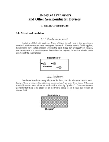
Because of the above point, transistors can be switched off & on at a very highfrequency. high enough to make modern computer speeds possible. A transistor switch can be controlled by a pulse-width modulated (PWM) signal,something that a mechanical switch can't do. Transistors don't bounce like a mechanical switch. A single control signal can control multiple circuits as each requires only a smallcurrent.NPN and PNP: What?!NPN and PNP refer to the arrangement of the pieces that make up the transister. Thepractical result is the direction of current flow.A bipolar junction transistor is made up of three pieces of silicon. Depending on whatis added to the silicon, it will be either N-type or P-type. An NPN transistor has apiece of P-type silicon (the base) sandwiched between two pieces of N-type (thecollector and emitter). In a PNP transistor, the type of the layers are reversed. Below isa typical cross section of a transistor. Adafruit IndustriesPage 5 of 21
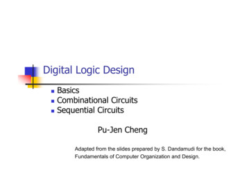
NPN and PNP transistors have verysimilar schematic symbols. The onlydifference is the direction of the arrow onthe emitter. In a NPN (on the left) it pointsoutward, for a PNP (on the right) it pointsinward.You can interpret that arrow in a coupleways: it's the direction of positive currentflow (opposite of electron flow), and alsoas pointing toward the lower voltagewhen the transistor is switched on, i.e. foran NPN the emitter has to be at a lowervoltage than the base/collector in orderfor it to conduct, whereas for a PNP it hasto be higher.Example usesSince a PNP transistor works more or less the opposite of an NPN, it can be usedwhere negative voltages are involved. One such example is in amplifying an ACsignal* for driving a speaker. A speaker moves air to create sound. While you can usea speaker with a DC signal (that varies between 0 and some positive voltage) thatpushes the speaker cone outward (and relax to it's neutral position) to create a soundwave, you can create louder sound if you also pull the cone back.Below is a simplified example of just that. when the input is positive, the NPNtransistor conducts and drives the output toward V. When the input is negative, thePNP transistor conducts, driving the output toward -V. Adafruit IndustriesPage 6 of 21
In my digital electronics tools learning guide is a DIY logic probe (https://adafru.it/Cox)that uses a PNP transistor to drive one of the LEDs. When the PROBE input is high, T1 switches on which, because of the resistors making up the voltage divider on itscollector and emitter, drops the voltage at the base of T2 enough below its emitter(at VCC ) to cause it to switch on, thus turning on LED1 . Adafruit IndustriesPage 7 of 21
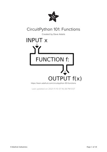
* An AC signal is one where the voltage can be positive and negative, and is typically constantlychanging.Darlington PairsSometimes you want to control a really large amount of current; more than a singletransistor's gain can provide. I.e. the output current has to be more than the inputcurrent multiplied by the transistor's gain.In this case we can combine two transistors in what is called a Darlingtion connection.In this configuration the gain of the pair is very slightly more than the product of thegain on the individual transistors and can be 1000 or more. Specifically, its theproduct of the gains plus the sum of the gains, but the product is usually high enoughthat the sum can be ignored for calculations.At its core, a Darlington pair is simply two transistors cascaded together: Adafruit IndustriesPage 8 of 21
A common Darlington pair is the TIP120 which is a great choice for the examples laterin this guide. It can handle up to 5A continuously (with bursts of 8A) and up to 60Vacross the collector and emitter. It has a gain of 1000.A TIP120 is just the circuit above packaged in a convenient 3-pin package (base,collector, and emitter). Since it's meant for power switching/amplification it comes witha metal backplate to which a larger heatsink can be attached.TIP120 Power Darlington Transistors - 3packTransistors are powerful little electronicswitches, and when our little NPNtransistors aren't power enough for yourproject, we have been known to usethese beefy TIP120.https://www.adafruit.com/product/976The "drive" connections of the CRICKIT are, in fact, darlington drivers. They are all ona single IC, called a ULN2803, with 7 or 8 Darlington's each with the following design: Adafruit IndustriesPage 9 of 21
This chip is very convenient to use as it provides everything needed: all the biasingresistors, and all the protection diodes needed for inductive loads such aselectromagnets, solenoids, and relays.The CRICKIT uses 4 of these drivers, though the chip contains 7. There are a variety ofversions of this design, some with 8 drivers in a slightly larger chip.ULN2803: 8 Channel Darlington Driver(Solenoid/Unipolar Stepper)Bring in some muscle to your output pinswith 8 mighty Darlingtons! This DIP chipcontains 8 drivers that can sink 500mAfrom a 50V supply and has kickbackdiodes included inside for.https://www.adafruit.com/product/970Open CollectorRather than output a signal we often want to provide a current sink. This is commonwhen controlling power to a circuit.An open-collector output is used to connect one side of the device being controlledto ground. The other side of the device will be connected to power. If you look at theCRICKIT "drive" outputs you will see that this is exactly what they are. You connect thepositive side of your device (a high power LED, solenoid, etc) to the 5v connectionand the negative side to a drive output. Adafruit IndustriesPage 10 of 21
Electrically the transistor in an opencollector configuration acts just like amechanical on-off switch (except with thebenefits listed previously).In another guide (https://adafru.it/Coy) we see another use of open collectorconnections: when the transistor switch is in its off state, the load is disconnected.One advantage of this is that multiple open collector connections and be tiredtogether and any one can turn on the load independent of the others, operating likean OR gate. Adafruit IndustriesPage 11 of 21
If we add a pull-up resistor instead of aload we get a logic circuit; each transistorfunctions as a tri-state inverter, togethermaking up a (in this case) 3-input NORgate. If A, B, and C are all low, none ofthe transistors are conducting (i.e. on)which means the output is high due tothe pull-up resistor. If any on the inputs ishigh, the corresponding transistor isswitched on, connecting the output toground.FETs Adafruit IndustriesPage 12 of 21
No. Not that Fet.FET as in Field Effect Transistor.It's a different way to build a transistor. A way that has some distinct advantages. Onemajor advantage for the usage we've been looking at is efficiency. FETs don't wasteas much power, which means they don't heat up as much as bipolar transistors.Another is that to control them takes a voltage and not a current, unlike a BJT (which,if you recall, is controlled by the base-emitter current).Because of their lower power/current characteristics, they are ideal to cram into asmall space. This makes them perfect for building large digital chips.We won't go into any more detail, but it's worth considering using a FET for highcurrent applications or where you want to avoid the wasted power and/or generatedheat.ExamplesDriving a LED StripA simple LED strip is a great example of a load. You simply control whether current isflowing through it. All you need to be concerned with is whether the control circuitcan supply enough current.These neon-like LED strips 'look' like one very big, high power LED - and they need12V to light up!Flexible Silicone Neon-Like LED Strip inVarious ColorsHere at Adafruit we love discovering newand exotic glowing things. Like moths tothe flame, we were intrigued by thesefresh Flexible Silicone Neon-Like LED.https://www.adafruit.com/product/3902 Adafruit IndustriesPage 13 of 21
Here we have a Gemma M0 using a PWM output (a 3.3v signal that can provide ahandful of milliamps) to drive a TIP120 Darlington Pair to control an led strip (noFritzing part for it yet, so a single LED is used as a proxy). The strip takes 12v and0.8A. aka 800 mA.The gain of the TIP120 is about 1000, so to get 0.8A through the strip, we need a basecurrent of 0.8mA. Erring on the side of being generous, a 2.2K bias resistor shouldgive a bit over 1mA of base current. That's plenty to drive the TIP120 into saturation.Here's the circuit in action. At the top you can see the TIP120. In the bottom-left is theGemmaM0 with the ground and control connected by the black and green clips,respecively. The other alligator clip is an insulated 3rd hand holding the Gemma. Onthe bench below is the LED strip which fades off and on due to the ramping PWMsignal. Adafruit IndustriesPage 14 of 21
The code running this demo is:import timeimport boardimport pulseioled pulseio.PWMOut(board.D2, frequency 5000, duty cycle 0)while True:for i in range(100):if i < 50:led.duty cycle int(i * 2 * 65535 / 100) # Upelse:led.duty cycle 65535 - int((i - 50) * 2 * 65535 / 100)time.sleep(0.05)# DownElectromagnets, Solenoids, and MotorsThese are electrically very similar: they are all inductive loads (made of a coil of wire)that can draw a moderate to high amount of current. As such they can't be controlleddirectly from a GPIO pin. This is where transistors come in.An electromagnet is a coil of wire around a core of magnetic material. When currentflows though the coil, a strong magnetic field is generated. I.e. it becomes a magnet.When the current stops, it ceases to be a magnet.A solenoid is basically an electromagnet in which the core and slide back and forthinside the coil. When current flows though the coil, the core moves. It can be used tocreate linear motion from a current. Ever have a electric model railroad? The switchespoints were moved by a solenoid.A motor is an arrangement of coils and permanent magnets such that controlling thecurrent through the coils (done inside the motor) causes the motor's shaft to spin,thus creating rotary motion from a current.For our purpose of turning them on and off, we can think of them as all just being aninductive load.Simon Monk did a guide on controlling a DC motor with an Arduino (https://adafru.it/dtG). Naturally, this used a transistor. Adafruit IndustriesPage 15 of 21
Since a transistor is a switch, it can be driven with a PWM signal. With a motor, ahigher duty cycle results is a faster rotation, i.e. higher speed.It's important to note the diode. When a motor stops, the magnetic field collapses andinduces a reverse current. That can be enough to burn out the transistor. The diodeserves to drain off that current harmlessly. Whenever you are controlling a motor orother inductive load, you must have a diode across it like this.1N4001 Diode - 10 packThis here is a 10 pack of the classic1N4001 power blocking diode. These aregood for reverse polarity protection (put itbetween your DC power jack and circuitryto avoid a.https://www.adafruit.com/product/755Not including the diode can destroy your microcontroller, not just the transistor! Adafruit IndustriesPage 16 of 21
Motor H bridgeThe above motor controller can turn the motor on and off, as well as control its speed,but it can only make it spin in one direction.To control the direction of the motor as well, it can be driven using an arrangement oftransistors called an H-bridge, shown below. Notice the resistors between each inputswitch and transistor base. These limit the current flowing through the base to justenough to drive it into saturation. Also, there is a diode between the pairs ofcollectors and power & ground. These allow the current generated when the motorstops to be drained away harmlessly. Without them the reverse current could blow outthe transistors, as mentioned earlier. Adafruit IndustriesPage 17 of 21
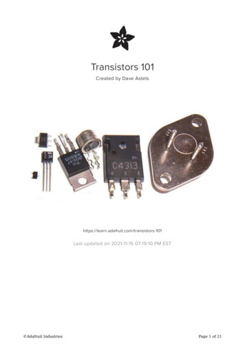
Here's the schematic of an H-Bridgemotor driver. Notice the use of PNPTransistors at the top (which connect themotor to Vcc) and NPN transistors at thebottom (which connect it to ground). Byenabling diagonally opposite pairs oftransistors the motor can be spun ineither direction by controlling thedirection which current flows through it.Below is a breadboard layout.That's a fair number of components which take up a fair bit of space. Thankfully, youcan get two of these packaged neatly onto a 16-pin chip: the DRV8833 which is used Adafruit IndustriesPage 18 of 21
on the CRICKIT. Technically the DRV8833 uses FET transistors but the operation ofthe circuit is identical.One handy feature of an H-bridge is that not only can it control forward and reverseoperation of the motor, but it also provides coast (the motor spins freely) and brake(the motor resists rotation) modes.See this post on robotroom.com (https://adafru.it/Coz) and the DRV8833 datasheet (https://adafru.it/CoA) for more details.FAQI let people know on the Adafruit Discord that I was working on this guide and askedfor questions. here are some of them.How do I pick a transistor for the job?The first thing to consider is the amount of current being controlled. If it's no morethan a couple dozen mA (e.g. for a simple LED) then something like a2N2222/2N3904 will be fine. For a higher current load like a LED strip or a solenoid, aDarlington pair like a TIP120 is a better choice. For high current control, considerusing a FET to minimize the waste and heat.How do I choose a bias resistor(s)?Assuming you want to use the transistor as a switch, then you want the bias resistorto ensure that the transistor is saturated when the input is high.For an example, the load you are controlling requires 200mA; that's the collectorcurrent Ic. Further let's use a typical transistor (such as a PN2222) that has a gain of 100 at that collector current. Looking at the datasheet (https://adafru.it/CoB) we seethat the Base-Emitter Saturation Voltage (on page 2) is 0.6v. That will cause thetransistor to saturate. If we control this with a 3.3v microcontroller then the biasresistor needs to have 3.3v - 0.6v 2.7v across it. With an I c of 200mA and a gain of100, we have a base current I b of Ic/gain 200mA/100 2mA. This is within therange of a typical GPIO pin's current rating*. We will need a resistor of 2.7v/2mA 2.7/0.002 1350 ohms. 1.2K ohms is a common value, and using a slightly lower biasresistor than the calculation indicates will result in a slightly higher base-emittercurrent and guarantee that the transistor is saturated when the input is high. Adafruit IndustriesPage 19 of 21
If you're not sure, or you don't want to do the math, a 1K resistor is a great place tostart. Reduce it if you need more current. Increase the resistor ohms if you want lesscurrent.How do I figure out how much heat will be generated?Heat generated by a transistor is measured in watts (W) and is computed bymultiplying the saturation voltage of the transistor (across the collector/emitter pins)by the collector-emitter current. The TIP120 used in the earlier example has asaturation voltage 2v when the current is 3A (and 4v when it's 5A). This informationwill be on the transistor's datasheet. So if we run 3A through it it will have a voltagedrop of 2v. That's 6W of power being dissipated as heat.In general, a TIP120 can disappate about 2W without a heatsink but it will get hot - sopick up a heat sink!How do I figure out what heat sink I'll need (if any)?Let's consider the TIP120 again. It's maximum working case temperature is 150C.Aiming to keep the temperature below 100C is a reasonable goal. That's well belowthe limit.To choose a heatsink we also need to know the ambient temperature where thetransistor will be operating. 50C is a reasonable guess if the circuit is enclosed with amoderate amount of circuitry. If it's lower there isn't a problem (it's easier to get rid ofexcess heat). The difference between the transistor case temperature we are aimingfor and the ambient is 50C. Again, reusing the above examples, the transistordissipates 6W. To choose a heatsink, we divide the temperature difference by thedissipated power: 50C/6W 8.3 C/W. This number is called thermal resistance. Aheatsink needs to be selected that has a thermal resistance of about 8.3 C/W.Since we chose 100C target which is well below the worst case, we can play around abit with the exact thermal resistance of the heatsink to work with size and supply. Thiswill also give us more options.For example, we can find a TO220 specific heatsink at Digikey with a thermalresistance of 9.0, yet is still rated for 6W at 50C: Adafruit IndustriesPage 20 of 21
* For example, a GPIO pin on the SAMD21 can provide up to 7mA.These simple clip on heat-sinks will let you handle a few extra Watts, and are easy touseTO-220 Clip-On HeatsinkGet the most out of your regulators,transistors and other TO-220 packagedchips by clipping on a heat-sink. Yourtransistor or regulator may advertise it canhandle high currents but.https://www.adafruit.com/product/977 Adafruit IndustriesPage 21 of 21
Nov 15, 2021 · Overview At their core, transistors amplify power. Note that: power. You can use a transformer to amplify either current or volta