Transcription
HowComputersWorkProcessor andMain MemoryRoger Young Copyright 2001, Roger Stephen YoungAll rights reserved.No part of this book may be reproduced, stored in a retrieval system, ortransmitted by any means, electronic, mechanical, photocopying, recording, orotherwise, without written permission from the author.1
FREEAn identical Internet version of this book is available forfree (for personal use and, possibly, for a limited time) athttp://howcomputers.comand/or ork/p1.htmlI’m atthinkorrr@yahoo.comand I’ll (possibly for a limited time) send you a free MicrosoftWord 2000 .doc file version (for personal use) as an attachmentto an email if you email me and want one.March 20, 20022
IntroductionComputers are the most complex machines that have ever been created. Very few peoplereally know how they work. This book will tell you how they work and no technicalknowledge is required. It explains the operation of a simple, but fully functional,computer in complete detail. The simple computer described consists mainly of aprocessor and main memory. Relays, which are explained, are used in the circuitryinstead of transistors for simplicity. This book does not cover peripherals like modems,mice, disk drives, or monitors.Did you ever wonder what a bit, a pixel, a latch, a word (of memory), a data bus, anaddress bus, a memory, a register, a processor, a timing diagram, a clock (of a processor),an instruction, or machine code is? Though most explanations of how computers workare a lot of analogies or require a background in electrical engineering, this book will tellyou precisely what each of them is and how each of them works without requiring anyprevious knowledge of computers or electronics. However, this book starts out very easyand gets harder as it goes along. You must read the book starting at the first page and notskip around because later topics depend on understanding earlier topics. How far you canget may depend on your background. A junior high school science background should beenough. There is no mathematics required other than simple addition and multiplication.This is a short book, but it must be studied carefully. This means that you will have toread some parts more than once to understand them. Get as far as you can. You will bemuch more knowledgeable about how computers work when you are done than when youstarted, even if you are not able to get through the whole text. This is a technical bookthough it is aimed at a non-technical audience. Though this book takes considerableeffort to understand, it is very easy for what it explains. After you have studied this book,if you go back and read it, it will seem simple. Good Luck!3
4
CONTENTSBASICS 7MEMORY . 43INSTRUCTIONS . 81PROCESSOR . 101PROGRAMMING . 132MISCELLANEOUS 1565
6
BASICS7
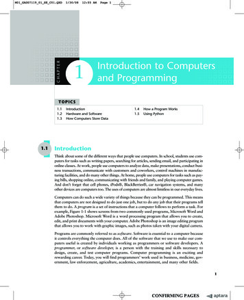
Simple CircuitThe picture above shows a ‘battery’ connected to a ‘light bulb’ by a ‘power wire’ and a‘ground wire.’ A power wire is a wire connected directly to the top of the battery. Aground wire is a wire connected directly to the bottom of the battery. Any electricalmachine is called a circuit.8
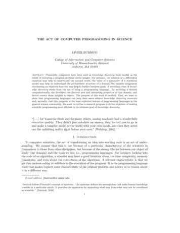
Simple DiagramThe diagram above also shows a ‘battery’ connected to a ‘light bulb’ by a ‘power wire’and a ‘ground wire.’ This diagram means the same as the picture on page 2. The groundwire is not shown because it is assumed that one connection of every light is alwaysconnected to the bottom of the battery by a ground wire in diagrams. Diagrams aresimpler to draw than pictures that mean the same thing.9
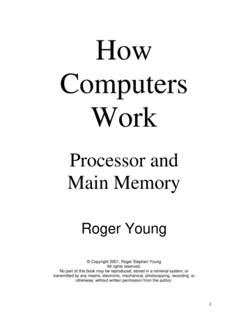
Key CircuitThe picture above shows the ‘top of’ a ‘battery’ connected by a ‘power wire’ to a ‘key’that is connected by a ‘light wire’ to a ‘light bulb.’A key is a flat piece of springy steel that is bent up so that the key only touches the wireto the key’s right when the key is pressed down by someone’s finger.When someone pushes the key down, the right end of the key touches the light wire andelectricity flows from the top of the battery, through the power wire, the key, and thelight wire, to the light bulb, turning the light bulb on.When the key is released, the key springs back up. Now the key does not touch the lightwire and electricity can not get from the key to the light wire to the light bulb so that thelight bulb goes off.10
Key DiagramThe diagram above shows the same circuit as the preceding picture.Again, there is also a wire from the other connection of the light bulb back to the bottomof the battery, but that wire does not need to be shown because the other connection ofevery light is connected to the bottom of the battery and you know the ground wire isthere without drawing it.11
ElectromagnetThe picture above shows the top of a battery connected by a wire to an electromagnet.An electromagnet is a coil of (plastic coated) wire. An electromagnet becomes magneticwhen electricity goes through it, just as a light bulb glows when electricity goes throughthe light bulb.The wire that makes up the coil of wire that is the electromagnet has two ends(connections). There is also a ‘ground wire’ from the other connection of theelectromagnet back to the bottom of the battery.12
Electromagnet DiagramThe diagram above shows the same circuit as the preceding picture.The wire that makes up the coil of wire that is the electromagnet has two ends(connections). There is also a ground wire from the other connection of theelectromagnet back to the bottom of the battery, as in the picture, but that wire does notneed to be shown because the other connection of every electromagnet is connected to thebottom of the battery.13
RelayThe picture above shows a ‘bottom key’ that controls an electromagnet.The electromagnet, in turn, controls the top key. A key and the electromagnet thatcontrols it are, together, called a relay. The relay is in the dashed box.When the bottom key is pressed, the electromagnet is powered and the electromagnetbecomes magnetic. That makes the electromagnet attract the top key and pull the top keydown just like a finger can push a key down. A magnet (or a powered electromagnet)attracts the top key because the top key is made of steel. A magnet (or a poweredelectromagnet) does not attract the wires because the wires are made of copper.Important: The electromagnet does not ever touch the top key. No electricity can gofrom the electromagnet to the wires attached to the top key.14
A computer is almost entirely made up of a lot of relays (today, transistors) connected bywires. Just how the relays are connected and just what they do is the main subject of thisbook. Other concepts, especially programming, will also be explained.(Today, transistors are used instead of relays for lower cost and greater speed. Thedesign remains practically the same, however. Relays are easier to understand and, so,will be used in this explanation.)Relay DiagramThe diagram above shows the same circuit as the previous picture in a different way.15
One Battery and Touching WiresIn this picture, only one battery powers all the circuitry in the previous picture. Note thesymbol for wires that touch.16
One Battery and Connected Wires DiagramThis diagram shows the same circuit as the previous picture in a different way. Touchingwires are connected wires.17
LoopLoop Diagram18
The picture and diagram at left show a relay that controls its own electromagnet! Thesquare of wire that takes electricity from the key of the relay to the electromagnet of thesame relay is called a ‘loop.’No electricity can get from the top of the battery to the electromagnet because the key isup. However, if someone presses the key, then electricity can get to the electromagnet.Then, the electromagnet will hold the key down - even if the person lets go of the key! Sowe say that the loop remembers that the key was pressed. Remember that the keynormally springs up because it is springy and bent upward.Similarly, if someone then lifts up the key (A person is much stronger than a littleelectromagnet.), then no electricity will reach the electromagnet and the key will remainup even after the person releases the key. So we say that the loop remembers that the keywas lifted up.Most relays in a computer are used to make loops, or connect the loops together.19
PixelPixel Diagram20
The picture and diagram above show a loop that controls a light bulb. A light bulb that iscontrolled by a loop is called a ‘pixel.’In a diagram, where a horizontal wire and a vertical wire meet, without crossing, there isa connection of the two wires.Therefore, when the key is pressed, electricity can flow from the top of the battery,through the key, to both the light and the electromagnet. When the key is down and thelight bulb is glowing, one says that the loop has value ‘1’ and the pixel is ‘on.’ The loophas value ‘1’ even if there is not a light bulb, just so the loop wire has electricity goingthrough it, to the electromagnet, because the key is down.When the key is up and the light bulb is not glowing, one says that the loop has value ‘0’and the pixel is ‘off.’ The loop has value ‘0’ even if there is not a light bulb - just so theloop wire does not have electricity going through it (because the key is up).21
Normally Closed KeyNormally Closed Key Diagram22
The picture and diagram at left show the top of a battery connected by a wire to anormally closed key, that is connected by another wire to a light bulb.A diagram of an electrical machine is called a circuit diagram, a diagram, a schematic(pronounced ske-ma’-tic) diagram, or just a schematic.The normally closed key is different from the keys described previously. The normallyclosed key is also a springy piece of steel, but is bent so that it normally is connected tothe right wire. Therefore, the light bulb in the circuit above is normally on. However, ifyou push down on the normally closed key, the light bulb becomes disconnected from the‘power wire’ and the light goes out.A key is called ‘closed’ when electricity can flow through it from a wire on its left to awire on its right.A key is called ‘open’ when electricity can’t flow through it from a wire on the left to awire on the right.A normally closed key is normally closed, but is open when you push it down.A normally open key is normally open, but is closed when you push it down.A relay is called closed if its key is closed.A relay is called open if its key is open.An electromagnet is called ‘powered’ if the electromagnet is connected to the top of abattery, even if that electromagnet is connected to the top of the battery through a seriesof closed keys. In fact, any piece of wire is called ‘powered’ if that piece of wire isconnected to the top of a battery, even if that piece of wire is connected to the top of thebattery through a series of closed keys.Any piece of wire that is powered is said to have value ‘1.’Any piece of wire that is not powered is said to have value ‘0.’The values of the wire in a loop as described previously are a special case of these rulesfor assigning values to wires.23
Normally Closed Relay24
Normally Closed Relay DiagramThe preceding picture and diagram show a bottom key that controls an electromagnet.The electromagnet, in turn, controls the top, normally closed key. A normally closed keyand the electromagnet that controls it are, together, called a normally closed relay.When the bottom key is pressed, the electromagnet is powered and the electromagnetbecomes magnetic. That makes the electromagnet attract the top, normally closed keyand pull the top, normally closed key down, just like a finger can push a normally closedkey down. A magnet (or a powered electromagnet) attracts the normally closed keybecause the normally closed key is made of steel. When the bottom key is pressed, thelight turns off.In other words, when the bottom key is pressed, the electromagnet energizes,disconnecting the top key.25
Clear KeyClear Key DiagramThe picture and diagram above show a loop as before, but a normally closed key has beenadded. As long as the normally closed key is closed, the loop works as before.However, if the normally closed key is pressed, then the normally closed key will beopen and electricity will not reach the electromagnet, so the electromagnet will not bemagnetic, and the normally open key will pop up if it was down. If the normally openkey already was up, it will stay up.Therefore, pressing the normally closed key will clear the value of the loop to ‘0.’Therefore, this normally closed key is called the ‘clear key’ for the loop.26
Loop to Loop Data TransferIn the circuit above, the ‘connecting key’ connects loop A and loop B. Both loops havevalue 0. Temporarily pressing ‘loop key A’ gives the value 1 to loop A. Now,temporarily pressing the ‘connecting key’ will make loop B have value 1. That isbecause when loop A has value 1, loop key A is closed, loop wire A has value 1, andwhen the connecting key is closed, electricity can reach the electromagnet of loop B,giving loop B value 1.However, if loop A has value 0, and loop B has value 0, and the connecting key ispressed, then both loops keep their values of 0.Therefore, if one temporarily presses ‘clear key B’ to clear loop B to value 0, and thentemporarily presses the connecting key, whatever value is in loop A will be copied to loopB. Then loop A and loop B will have the same value.27
OscillatorOscillator Diagram28
The picture and diagram at left show a normally closed relay that controls its ownelectromagnet. The square of wire that takes electricity from the normally closed key ofthe relay to the electromagnet of the same normally closed relay is called a feedbackwire. (Notice that this circuit is different from a loop circuit, which uses a normally openrelay.) This circuit is called an oscillator because the relay oscillates (changes back andforth) between open and closed.Electricity can get from the top of the battery, through the closed, normally closed relaykey to the electromagnet. The electromagnet then pulls the normally closed key downand opens the normally closed key. Because the normally closed key is now open, noelectricity can get to the electromagnet. The electromagnet now no longer attracts thenormally closed key and the normally closed key closes.Thus, the normally closed key repeatedly opens and closes without anyone touching thekey. The feedback wire gets value 1, then value 0, then value 1, etc. It takes a relayabout a hundredth of a second to change values.Just as a normal loop is the basis of a computer memory, this feedback circuit is a keypart of a computer’s clock. A computer’s clock is a circuit that repeatedly generatessignals (1 and 0 values).29
Keys in SeriesKeys in Series DiagramIn the picture and diagram above, one must press both ‘key D’ AND ‘key E’ to turn thelight on.30
AND Gate CircuitIn the circuit above, the three triangles are all the top of the same battery. When ‘key D’AND ‘key E’ close, then the light comes on. When ‘key A’ is pressed, then ‘key D’closes. When ‘key B’ is pressed, then ‘key E’ closes. Therefore, when ‘key A’ and ‘keyB’ are pressed, the light turns on. Another way of describing the operation of the circuitis to say that ‘output wire C’ gets value 1 only when ‘input wire A’ gets value 1 AND‘input wire B’ gets value 1.The following table also shows that ‘output wire C’ has value 1 only when both ‘inputwire A’ has value 1 AND ‘input wire B’ has value 1.AND gate truth tableABC00110101000131
AND Gate Circuit with SymbolThe diagram above shows a circuit with the symbol for an ‘AND gate’ which is shown,alone, below.AND Gate SymbolThe light in the circuit below only comes on whey key D, key E, AND key F are allpressed.Three Keys in Series32
Keys in ParallelKeys in Parallel DiagramIn the picture and diagram above, one need only press either ‘key D’ OR ‘key E’ (orboth) to turn the light on.33
OR Gate CircuitIn the circuit above, as always, the crossing wires do not touch and are not connected toeach other. When ‘key D’ OR ‘key E’ (or both) closes, the light comes on. When ‘keyA’ is pressed, then ‘key D’ closes. When ‘key B’ is pressed, then ‘key E’ closes.Therefore, when ‘key A’ OR ‘key B’ is pressed, the light turns on. Another way ofdescribing the operation of this circuit is to say that ‘output wire C’ gets value 1 onlywhen ‘input wire A’ has value 1 OR ‘input wire B’ has value 1.The following table also shows that ‘output wire C’ gets value 1 only when either ‘inputvalue A’ has value 1 OR ‘input wire B’ has value 1.OR gate truth tableABC00110101011134
OR Gate Circuit with SymbolThe diagram above shows a circuit with the symbol for an ‘OR gate’ which is shownalone, below.OR Gate Symbol35
Three Keys in ParallelThe light in the circuit above turns on when key D, key E, OR key F is pressed.36
Normally Closed KeyNormally Closed Key DiagramIn the picture and diagram above, the light is on, as we have seen before. One must pressthe normally closed key D down to turn the light off.37
NOT Gate CircuitIn the circuit above, the triangles are both the top of the same battery. When ‘key A’ ispressed, ‘key D’ is pulled down and the light goes off. That is, when ‘key A’ is pressed,normally closed ‘key D’ opens. Therefore, when ‘key A’ is pressed, the light goes off.Another way of describing the operation of the circuit is to say that ‘output wire C’ getsvalue 0 when ‘input wire A’ gets value 1. ‘Output wire C’ gets value 1 when ‘input wireA’ gets value 0.The following table also shows that ‘output wire C’ gets value 0 only when ‘input wireA’ gets value 1.NOT gate truth tableAC011038
NOT Gate Circuit with SymbolThe diagram above shows a circuit with the symbol for a ‘NOT gate’ which is shownalone, below.NOT Gate Symbol39
Interconnected GatesThe diagram above shows that the output of an AND gate can be the input for a NOTgate. The circuit above can also be represented with gate symbols as below.Interconnected Gates with Symbols40
A ‘NAND gate’ can be constructed from an AND gate followed by a NOT gate asindicated below.Constructed NAND GateA NAND gate can be represented by the single symbol in the circuit below.NAND Gate Circuit41
A lone NAND gate is pictured below.NAND GateThe truth table for the NAND gate is shown below.NAND gate truth tableABC00110101111042
MEMORY43
(Address) Decoder44
The diagram at left shows a ‘decoder.’ A and B are the inputs to the decoder and I, J, K,and L are the outputs. The truth table for this circuit is shown below.A B IJ K L001101000101100000100001Normally closed relay AA is closed. Normally closed relay AB is also closed.Therefore, electricity can travel from the top of the battery, through AA and AB, to lightI.If keys A and B are both pressed, then normally open relays DA and DB are closed(because their electromagnets are powered) and electricity can reach light L.Similarly, if key A is pressed and key B is not pressed, then normally open relay CA isclosed and normally closed relay CB is closed and light K is on.Finally, if key A is not pressed and key B is pressed, then light J is on.Wire PO is power. A1 and A0 are address wire 1 and address wire 0. PO has value 1.A1 can have value 1 or 0, and A0 can have value 1 or 0.45
Truth Table Generator46
In the preceding circuit, keys A and B are the inputs and lights G and H are the outputs.The truth table for the circuit above is shown below.A B G H0011010110010101For example, if neither A nor B is pressed, then S00 is powered (has value 1) because thenormally closed relays AA and AB are then closed. BB is open so S01 is 0, CA is openso S10 is 0, and both DA and DB are open so S11 is 0. Because S00 is powered, AG isclosed and electricity can go from the top of the battery (indicated by a triangle), throughrelay AG, to wire D1 to light G, so G is on. Relay AI is also closed but relay AI’s key isnot connected to the top of the battery so no electricity gets to light H.For another example, if both keys A and B are pressed, then A 1 and B 1 and relays DAand DB are closed. That makes S11 1 and closes relays DG and DI. Electricity can gofrom the top of the battery through DG and D1 to light G and through DI and D2 to lightH. Therefore, A 1 and B 1 results in G 1 and H 1 as in the truth table.D1 and D0 are data wire 1 and data wire 0. D1 can have value 1 or 0 and D0 can be 1 or0.47
ROM (Read-Only Memory) With Enable (EN) Key (D)48
The circuit above has the following truth table:EN A1 A0 D1 D00000111100110011010101010000100100000101If key D (EN) is not pressed (‘EN’ stands for ‘enable.’), then EN is 0, so no electricitygets to the electromagnets of AG and AI. Similarly, BG, BI, CG, CI, DG, and DI areopen if D (EN) is not pressed. Therefore, if D (EN) is not pressed, then no electricity canget to lights G and H as indicated in the truth table.If A and B are not pressed (A1 0 and A0 0), then electricity gets to the electromagnet ofAE and closes relay AE. If D is then pressed (EN 1), then electricity can go from the topof the battery, through D and through AE to the electromagnets of AG and AI. AG andAI then close and electricity can go from the top of the battery, through AG, to wire D1and light G.The truth table above can also be represented as below.EN A1 A0 D1 D001111X0011X01010100100101The X’s mean 0 or 1. That is, the row with X’s means that if EN is 0, then D1 0 andD0 0 no matter what values A1 and A0 have.49
Loops Added50
In the circuit above, eight loops have been added to the previous circuit. The loops arelabeled AF, AH, BF, BH, CF, CH, DF, and DH. Each loop can have value 0 or 1. Thetruth table fore this circuit is shown below.EN01111A1 A0 D1D0X00110AHBHCHDHX01010AFBFCFDFTo make loop AF have value 1, just press key AF down. Key AF will stay down becauseit is part of a loop. To make AF have value 0 again, just lift key AF up. It will stay up onits own. In the truth table, ‘AF’ means the value of loop AF. The other loops, AH, BF,BH, CF, CH, DF, and DH, operate similarly.51
Input Keys Added52
In the diagram at left, key E and key F (bottom right) have been added to the circuit.Keys E and F allow one to set a loop to value 1 without touching the loop’s key.For example, to set loop AF to 1 without touching key AF, one must not push key A orkey B, which closes relay AE. Then you hold down key E to put value 1 on wire D1.Finally, temporarily pushing key D makes EN temporarily 1. Because AE is closed,EN 1 powers relay AG’s electromagnet and closes AG. D1’s value of 1 can now gothrough key AG to loop AF, thereby making loop AF have value 1.53
Memory (Clear Key Added)54
In this circuit, key C, wire CL (for CLear), relays AC, BC, CC, and DC, normally closedrelays AD, BD, CD, and DD, and wires H00, H01, H10 and H11 (H for Hold, orremember) have been added to the circuit. These additions allow loops to be ‘cleared’ tovalue 0 by manipulating keys outside the dashed box (memory) without touching the loopkeys.The diagram above shows a memory within the dashed box. The memory can becontrolled by the keys outside the dashed box at the bottom of the diagram. What amemory does will be explained first. Then, how the memory works will be described.AF, AH, BF, BH, CF, CH, DF, and DH are each relay keys of loops. You can change thevalue of loop AF from 0 to 1 by simply pressing key AF down. Similarly, you canchange the value of loop AF from 1 to 0 by lifting key AF. To determine whether a loophas value 0 or value 1, just look at the loop’s key. If the key is down, then the loop hasvalue 1. If the key is up, then the loop has value 0. The value of a loop stays the sameuntil you change it.However, suppose that the dashed box was a physical box and you could not reach insidethe box. If you buy a memory chip at a store, the circuitry is enclosed in a plastic boxwith wires PO, A1, A0, CL (This may be called WR for ‘WRite.’), EN, D1, D0 andGRound wire, GR, sticking out. The circuitry uses transistors instead of relays forswitches, so even if you broke the box open, you couldn’t change the values by hand. (Amemory from a store would probably have more address lines (wires) like A2, A3, .A20 and data lines like D2, D3, . D7.)The memory is constructed so that the values in the loops can be examined and changedusing only keys A, B, C, D, E, and F and light bulbs G and H which are all outside thebox and are not part of the memory.55
Where Power Reaches in a Memory56
The bold wires in the diagram at left, show which wires are powered.A wire is powered only if it is connected to the top of the battery (represented by atriangle in the lower left corner of the diagram, as shown below).powerNotice the new symbol used for keys AC and AE. Keys AC and AE are normally openkeys. However, they are closed now because their electromagnets are powered.Therefore, they are represented as:closed, normally open keyinstead of as:open, normally open keyElectricity can flow from left to right (or right to left) through a closed key even if it’s aclosed but normally open key.57
Similarly, an open, normally closed key is represented as:open, normally closed keyinstead of as:closed, normally closed key58
Notice that, in the diagram of memory, all of the loops (AF, AH, BF, BH, CF, CH, DF,and DH) have value 0 because all of those normally open keys are open.AF is ‘bit 1’ of ‘latch 00’ and has value 0. AH is bit 0 of latch 00 and also has value 0.You should follow the power from the top of the battery (the triangle in the lower left ofthe diagram of memory above) and see why certain wires are bold and the rest arenormal. Remember, electricity can’t go through open keys. Electricity also does nottravel between crossing wires. Crossing wires are not touching (not connected). Youshould also understand why some electromagnets are powered and others aren’t, and howpowering the electromagnet of a key closes a normally open key and, in later diagrams,opens a normally closed key.59
Now, suppose we want to store value 01 in latch 10. This means we want to keep key CFopen for value 0 and close key CH for value 1. This is called ‘writing’ value 01 toaddress 10.To do this, you first select latch 10 by pressing key A and not pressing key B. Thisselects latch 10 as indicated by the bold select 10 wire, ‘S10,’ in the diagram below. KeyA controls address wire 1, labeled A1 in the diagram, and key B controls address wire 0,labeled A0 in the diagram. Both address wires, A1 and A0, together, are called theaddress bus. A group of similar wires are, together, called a ‘bus.’ Pressing key A andnot pressing key B results in power going through the circuit as indicated by bold lines inthe diagram below. Notice that horizontal wire S10 has power (is bold) while S00, S01,and S11 do not have power. This selects latch 10.60
Selecting the Address61
The second step in writing value 01 to address (latch) 10 is to press key F and not presskey E as in the following diagram. Not pressing key E gives value 0 to data wire D1 andpressing key F gives value 1 to data wire D0. Both data wires, D1 and D0, are, together,called the ‘data bus’ just as both address wires, A1 and A0, are, together, called the‘address bus.’ The first and second steps can be done simultaneously. This results inpower going through the circuit as indicated by the bold wires in the diagram below.Wire D0 is bold and, so, has value 1.62
Selecting the Data to be Written63
The third step in writing 01 to address 10 is pressing the enable key, ‘D,’ which controlsthe enable (‘EN’) wire. This results in power going through the circuit as indicated inbold in the following diagram. Notice that loop CH now has value 1. Loop CH gotpower from wire D0 through CI. No power went from wire D1 through CG to loop CFbecause wire D1 is not powered.It’s important to remember that pressing the enable key, ‘D,’ makes EN 1 and connectsthe loops of the selected (by the address wires A1 and A0) latch to the data bus wires, D1and D0.64
Pressing Enable (EN)65
In the fourth step, key D is released and the enable (EN) wire returns to value 0(unpowered). This results in power flowing through the memory as indicated by boldwires in the following diagram. Notice that loop CH still has value 1 even though loopCH is no longer connected to data wire D0 through relay CI (because relay CI is open).66
Releasing Enable (EN)67
Step five: Keys A and F are released and address wire A0 and data wire D0 get value 0(as indicated in the following diagram). Notice that loop CH still has value 1.Therefore, to write value 01 to latch 10, you press A and not B to select latch 10; and, tochoose data 01, do not push E and push F. This makes wire A1 have value 1, wire A0have value 0, wire D1 have value 0, and wire D0 have value 1. Then, while holding Aand F down, temporarily press D to make the enable wire, EN, temporarily 1. Then,release A and F. This can be described as follows.1. Select the address and data with the address and data keys A, B, E, and F (A1, A0, D1and D0).2. Temporarily press D (EN).3. Release the address and data keys.That’s all there is to storing data in an empty latch.68
Releasing the Address and Data Keys69
To find out what is in a latch, do the following.1. Select the address of the latch you want to read with keys A (wire A1) and B (wireA0).2. Press key ‘D’ to make the ‘EN’ wire have value 1. The lights G and H will indicatethe values of the data bits stored in that latch.3. Release the enable key D.4. Release the address keys, A and B.For example, to read latch 10, first press key A (and not key B) to select latch 10 (asindicated in the following diagram).70
Selecting the Address to Read71
Second, press key D to make the enable (EN) wire have value 1. Then
A computer is almost entirely made up of a lot of relays (today, transistors) connected by wires. Just how the relays are connected and just what they do is the main subject of this book. Other concepts, especially programming, will also be explained. (Today, transistors are use