Transcription
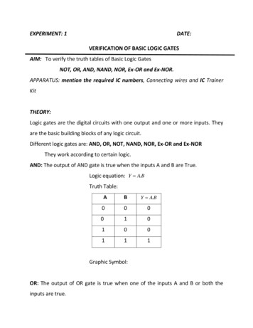
Digital Logic Design BasicsBiCombinational CircuitsSequential CircuitsPu-Jen ChengAdapted from the slides prepared by S. Dandamudi for the book,Fundamentals of Computer Organization and Design.
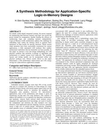
Introduction to Digital Logic Basics Hardware consists of a few simple building blocks¾ These are called logic gates AND, OR, NOT, NAND, NOR, XOR, L i gatesLogict are bbuiltilt usingi ttransistorsi t NOT gate can be implemented by a single transistorAND gate requires 3 transistorsTransistors are the fundamental devices Pentium consists of 3 million transistorsCompaq Alpha consists of 9 million transistorsNow we can build chips with more than 100 milliontransistors
Basic Concepts Simple gates¾¾¾ Functionality can beexpressed by a truth table¾ ANDORNOTA truth table lists output foreach possible inputcombinationPrecedence¾¾NOT AND ORF AB AB (A (B)) ((A) B)
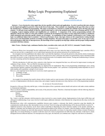
Basic Concepts (cont.) Additional useful gates¾¾¾ NANDNORXORNAND AND NOTNOR OR NOTXOR implementsexclusive-OR functionNAND and NOR gatesrequire only 2 transistors¾AND and OR need 3transistors!
Basic Concepts (cont.) Number of functions¾¾¾¾With N logical variables, we can defineN22 functionsSome of them are useful AND,AND NAND,NAND NOR,NOR XOR,XOR Some are not useful: Output is always 1 Output is always 0“Number of functions” definition is useful in provingcompleteness property
Basic Concepts (cont.) Complete sets¾A set of gates is complete If we can implement any logical function using onlythe type of gates in the set ¾¾You can uses as many gates as you wantSome example complete sets {AND, OR, NOT}Not a minimal complete set {AND, NOT} {OR, NOT} {NAND} {NOR}Minimal complete set A complete set with no redundant elements.
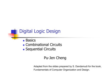
Basic Concepts (cont.) Proving NAND gate is universalNAND gate is called universal gate
Basic Concepts (cont.) Proving NOR gate is universalNOR gate is called universal gate
Logic Chips
Logic Chips (cont.) Integration levels¾¾¾¾SSI (small scale integration) Introduced in late 1960s 1-10 gates (previous examples)MSI (medium scale integration) Introduced in late 1960s 10-100 gatesLSI (large scale integration) Introduced in early 1970s 100-10,000 gatesVLSI (very large scale integration) Introduced in late 1970s More than 10,000 gates
Logic Functions Logical functions can be expressed in severalways:¾¾¾ Truth tableLogical expressionsGraphical formExample:¾Majority function Output is 1 whenever majority of inputs is 1 We use 3-input majority function
Logic Functions (cont.)3-input majority functionABCF00000001111011001110101010010111 Logical expression formF AB BC AC
Logical Equivalence All three circuits implement F A B function
Logical Equivalence (cont.) Proving logical equivalence of two circuits¾¾Derive the logical expression for the output of eachcircuitShow that these two expressions are equivalent Two ways: You can use the truth table method For every combination of inputs, if both expressionsyield the same output, they are equivalent Good for logical expressions with small number ofvariablesYou can also use algebraic manipulation Need Boolean identities
Logical Equivalence (cont.) Derivation of logical expression from a circuit¾Trace from the input to output Write down intermediate logical expressions along the path
Logical Equivalence (cont.) Proving logical equivalence: Truth table methodA0011B0101F1 A B0001F3 (A B) (A B) (A B)0001
Boolean Algebra
Boolean Algebra (cont.)
Boolean Algebra (cont.) Proving logical equivalence: Boolean algebramethod¾To prove that two logical functions F1 and F2 areequivalent Start with one function and apply Boolean laws toderive the other function Needs intuition as to which laws should be appliedand when Practice helpsSometimes it may be convenient to reduce bothfunctions to the same expressionExample: F1 A B and F3 are equivalent ¾A B (A B) (A B) (A B)
Logic Circuit Design Process A simple logic design process involves¾¾¾¾¾Problem specificationTruth table derivationDerivation of logical expressionSimplification of logical expressionI lImplementationt ti
Deriving Logical Expressions Derivation of logical expressions from truth tables¾¾ SOP form¾¾ sum-of-products (SOP) formproduct-of-sums (POS) formWriteWi an AND term ffor eachh iinput combinationbi i thathproduces a 1 output Write the variable if its value is 1; complementotherwiseOR the AND terms to get the final expressionPOS form¾Dual of the SOP form
Deriving Logical Expressions (cont.) A3-input majority functionBCF00000001111011001110101010010111 SOP logical expressionFour product terms¾Because there are 4 rowswith a 1 outputF ABC ABC ABC ABC
Deriving Logical Expressions (cont.) A3-input majority functionBCF00000001111011001110101010010111 POS logical expressionFour sum terms¾Because there are 4 rowswith a 0 outputF (A B C) (A B C)(A B C) (A B C)
Logical Expression Simplification Two basic methods¾Algebraic manipulation Use Boolean laws to simplify the expression ¾Difficult to useDon’t know if you have the simplified formKarnaugh map (K-map) method Graphical method Easy to use Can be used to simplify logical expressions with a fewvariables
Algebraic Manipulation Majority function exampleAdded extraABC ABC ABC ABC ABC ABC ABC ABC ABC ABC We can now simplify this expression asBC AC AB A difficult method to use for complex expressions
Karnaugh Map MethodNote the order
Karnaugh Map Method (cont.)Simplification examples
Karnaugh Map Method (cont.)First and last columns/rows are adjacent
Karnaugh Map Method (cont.)Minimal expression depends on groupings
Karnaugh Map Method (cont.)No redundant groupings
Karnaugh Map Method (cont.) Example¾¾Seven-segment displayNeed to select the right LEDs to display a digit
Karnaugh Map Method (cont.)
Karnaugh Map Method (cont.)Don’t cares simplify the expression a lot
Implementation Using NAND Gates Using NAND gates¾Get an equivalent expressionAB CD AB CD¾UsingUg ded Morgan’so galawaAB CD AB.CD¾Can be generalized Majority functionA B B C AC A B . BC . ACIdea: NAND Gates: Sum-of-Products, NOR Gates: Product-of-Sums
Implementation Using NAND Gates (cont.) Majority function
Introduction to Combinational Circuits Combinational circuits Combinational circuits provide a higher level ofabstraction¾¾ Output depends only on the current inputsHelpHl ini reducingd i designd i complexityl itReduce chip countWe look at some useful combinational circuits
Multiplexers Multiplexer¾¾¾ 2n data inputsn selection inputsa single outputSelection inputdetermines theinput that shouldbe connected tothe output4-data input MUX
Multiplexers (cont.)4-data input MUX implementation
Multiplexers (cont.)MUX implementations
Multiplexers (cont.)Example chip: 8-to-1 MUX
Multiplexers (cont.)Efficient implementation: Majority function
Demultiplexers (DeMUX) Demultiplexer¾¾¾a single inputn selection inputs2n outputs
Decoders Decoder selects one-out-of-N inputs
Decoders (cont.)Logic function implementation
Comparator Used to implement comparison operators ( , , , , )
Comparator (cont.)A B: Ox Ix (x A B, A B, & A B)4-bit magnitude comparator chip
Comparator (cont.)Serial construction of an 8-bit comparator
1-bit Comparatorx yCMPx yx yxxyyx y x y x y
8-bit comparatorxn ynxn ynx yCMPxn ynx yx yxy
Adders Half-adder¾¾ Adds two bits Produces a sum and carryProblem: Cannot use it to build larger inputsF ll ddFull-adder¾¾Adds three 1-bit values Like half-adder, produces a sum and carryAllows building N-bit adders Simple technique Connect Cout of one adder to Cin of the nextThese are called ripple-carry adders
Adders (cont.)
Adders (cont.)A 16-bit ripple-carry adder
Adders (cont.) Ripple-carry adders can be slow¾ Delay proportional to number of bitsCarry lookahead adders¾¾Eliminate the delay of ripple-carry addersCarry-insCarryins are generated independently C0 A0 B0 C1 A0 B0 A1 A0 B0 B1 A1 B1.Requires complex circuitsUsually, a combination carry lookahead andripple-carry techniques are used ¾¾
Programmable Logic Arrays PLAs¾¾¾Implement sum-of-product expressions No need to simplify the logical expressionsTake N inputs and produce M outputs Each input represents a logical variable Each output represents a logical function outputInternally uses An AND array Each AND gate receives 2N inputs N inputs and their complementsAn OR array
Programmable Logic Arrays (cont.)A blank PLA with 2 inputs and 2 outputs
Programmable Logic Arrays (cont.)Implementation examples
Programmable Logic Arrays (cont.)Simplified notation
1-bit Arithmetic and Logic UnitPreliminary ALU design2’s complementRequired 1 is added via Cin
1-bit Arithmetic and Logic Unit (cont.)Final design
Arithmetic and Logic Unit (cont.)16-bit ALU
Arithmetic and Logic Unit (cont’d)4-bit ALU
Introduction to Sequential Circuits Output depends on current as well as past inputs¾¾ Depends on the historyHave “memory” propertySequential circuit consists ofCombinationalCbi il circuiti i Feedback circuitPast input is encoded into a set of state variables Uses feedback (to feed the state variables) ¾ Simple feedbackUses flip flops
Introduction (cont.)Main components of a sequential circuit
Clock Signal
Clock Signal (cont.) Clock serves two distinct purposes¾Synchronization point Start of a cycle End of a cycleIntermediate point at which the clock signal changeslevelsTiming information Clock period, ON, and OFF periods ¾ Propagation delay¾Time required for the output to react to changes in theinputs
Clock Signal (cont.)
SR Latches Can remember a bitLevel-sensitive (not edge-sensitive)A NOR gate implementation of SR latch
SR Latches (cont.) SR latch outputs follow inputsIn clocked SR latch, outputs respond at specific instances¾Uses a clock signal
D Latches D Latch¾Avoids the SR 11 state
Positive Edge-Triggered D Flip-Flops Edge-sensitive devices¾Changes occur either at positive or negative edges
Notation for Latches & Flip-Flops Not strictly followed in the literatureLatchesLow levelHigh levelFlip-flopsPositive edgeNegative edge
Example of Shift Register Using D Flip-Flops74164 shiftRegister chip
Memory Design Using D Flip-FlopsRequire separate data in and out lines
JK Flip-FlopsJK flip-flop(master-slave)J0011K0101Qn 1Qn01Qn
Examples of D & JK Flip-FlopsTwo example chipsD latchesJK flip-flops
Example of Shift Register Using JK Flip-Flops Shift Registers¾Can shift data left or right with each clock pulseA 4-bit shift register using JK flip-flops
Example of Counter Using JK Flip-Flops Counters¾¾Easy to build using JK flip-flops Use the JK 11 to toggleBinary counters Simplep designg Ripple counter B bits can count from 0 to 2B 1Increased delay as in ripple-carry addersDelay proportional to the number of bitsSynchronous counters Output changes more or less simultaneouslyAdditional cost/complexity
Modulo-8 Binary Ripple Counter Using JK Flip-FlopsLSB
Synchronous Modulo-8 Counter Designed using the following simple rule¾Change output if the preceding count bits are 1 Q1 changes whenever Q0 1Q2 changes whenever Q1Q0 11
Example Counters
Sequential Circuit Design Sequential circuit consists of¾¾ A combinational circuit that produces outputA feedback circuit We use JK flip-flops for the feedback circuitSi l counterSimplet examplesl usingi JK flip-flopsfli fl¾¾Provides alternative counter designsWe know the output Need to know the input combination that producesthis output Use an excitation table Built from the truth table
Sequential Circuit Design (cont.)
Sequential Circuit Design (cont.) Build a design table that consists of¾¾¾ Current state outputNext state outputJK inputs for each flip-flopBiBinarycountert examplel¾¾¾¾3-bit binary counter3 JK flip-flops are neededCurrent state and next state outputs are 3 bits each3 pairs of JK inputs
Sequential Circuit Design (cont.)Design table for the binary counter example
Sequential Circuit Design (cont.)Use Kmaps tosimplifyexpressions for JKinputs
Sequential Circuit Design (cont.) Final circuit for the binary counter example¾Compare this design with the synchronous counter design
Sequential Circuit Design (cont.) A more general counterdesign¾Does not step in sequence0 3 5 7 6 0 Same design processOne significant change¾Missing states 1, 2, and 4Use don’t cares for thesestates
Sequential Circuit Design (cont.)Design tablefor thegeneralcounterexample
Sequential Circuit Design (cont.)K-maps tosimplify JKinputpexpressions
Sequential Circuit Design (cont.)Final circuit for the general counter example
General Design Process FSM can be used to express the behavior of asequential circuitCounters are a special caseState transitions are indicated by arrows with labels X/Y X: inputs that cause system state change Y: output generated while moving to the next state ¾ Look at two examples¾¾Even-parity checkerPattern recognition
General Design Process (cont.) Even-parity checker¾FSM needs to remember one of two facts ¾Number of 1’s is odd or evenNeed only two states 0 input does not change the state 1 input changes stateSimple example Complete the design as an exercise
General Design Process (cont.) Pattern recognition example¾¾¾Outputs 1 whenever the input bit sequence has exactlytwo 0s in the last three input bitsFSM requires thee special states to during the initialphase S0 S2After that we need four states S3: last two bits are 11 S4: last two bits are 01 S5: last two bits are 10 S6: last two bits are 00
General Design Process (cont.)State diagramfor the patternrecognitionexample
General Design Process (cont.) Steps in the design process1.2.Derive FSMState assignment Assign flip-flop states to the FSM states 3.4.5.Necessary to get an efficient designDesign table derivation Derive a design table corresponding to theassignment in the last stepLogical expression derivation Use K-maps as in our previous examplesImplementation
General Design Process (cont.) State assignment¾Three heuristics Assign adjacent states for ¾states that have the same next statestates that are the next states of the same stateStates that have the same output for a given inputFor our example22 Heuristic 1 groupings: (S1, S3, S5) (S2, S4, S6)33 Heuristic 2 groupings: (S1, S2) (S3, S4) (S5, S6) Heuristic 1 groupings: (S4, S5)
General Design Process (cont.)State table for thepatternrecognitionexample
General Design Process (cont.)State assignmentK-map for state assignment
General Design Process (cont.)Designtable
General Design Process (cont.)K-maps for JK inputsK-map for the output
General Design Process (cont.)Final implementation
Introduction to Digital Logic Basics Hardware consists of a few simple building blocks ¾These are called logic gates AND, OR, NOT, NAND, NOR, XOR, L i t b ilt i t i tLogic gates are built using transistors NOT gate can be implemented by a single transistor AND gate requires 3 transistors Transistors are the fund