Transcription
Autodesk PowerMill 2017RobotHow to build a Robot simulation
AutodeskPowerMill20172016 Delcam Limited. All Rights Reserved. Except where otherwisepermitted by Delcam Limited, this publication, or parts thereof, may not bereproduced in any form, by any method, for any purpose.Certain materials included in this publication are reprinted with the permissionof the copyright holder.TrademarksThe following are registered trademarks or trademarks of Autodesk, Inc.,and/or its subsidiaries and/or affiliates in the USA and other countries: 123D,3ds Max, Alias, ArtCAM, ATC, AutoCAD LT, AutoCAD, Autodesk, the Autodesklogo, Autodesk 123D, Autodesk Homestyler, Autodesk Inventor, AutodeskMapGuide, Autodesk Streamline, AutoLISP, AutoSketch, AutoSnap, AutoTrack,Backburner, Backdraft, Beast, BIM 360, Burn, Buzzsaw, CADmep, CAiCE,CAMduct, Civil 3D, Combustion, Communication Specification, Configurator360, Constructware, Content Explorer, Creative Bridge, Dancing Baby (image),DesignCenter, DesignKids, DesignStudio, Discreet, DWF, DWG, DWG(design/logo), DWG Extreme, DWG TrueConvert, DWG TrueView, DWGX, DXF,Ecotect, Ember, ESTmep, FABmep, Face Robot, FBX, FeatureCAM, Fempro,Fire, Flame, Flare, Flint, ForceEffect, FormIt 360, Freewheel, Fusion 360, Glue,Green Building Studio, Heidi, Homestyler, HumanIK, i-drop, ImageModeler,Incinerator, Inferno, InfraWorks, Instructables, Instructables (stylized robotdesign/logo), Inventor, Inventor HSM, Inventor LT, Lustre, Maya, Maya LT,MIMI, Mockup 360, Moldflow Plastics Advisers, Moldflow Plastics Insight,Moldflow, Moondust, MotionBuilder, Movimento, MPA (design/logo), MPA, MPI(design/logo), MPX (design/logo), MPX, Mudbox, Navisworks, ObjectARX,ObjectDBX, Opticore, P9, PartMaker, Pier 9, Pixlr, Pixlr-o-matic, PowerInspect,PowerMill, PowerShape, Productstream, Publisher 360, RasterDWG, RealDWG,ReCap, ReCap 360, Remote, Revit LT, Revit, RiverCAD, Robot, Scaleform,Showcase, Showcase 360, SketchBook, Smoke, Socialcam, Softimage, Spark& Design, Spark Logo, Sparks, SteeringWheels, Stitcher, Stone, StormNET,TinkerBox, Tinkercad, Tinkerplay, ToolClip, Topobase, Toxik, TrustedDWG, TSplines, ViewCube, Visual LISP, Visual, VRED, Wire, Wiretap, WiretapCentral,XSIAll other brand names, product names or trademarks belong to theirrespective holders.DisclaimerTHIS PUBLICATION AND THE INFORMATION CONTAINED HEREIN IS MADEAVAILABLE BY AUTODESK, INC. "AS IS." AUTODESK, INC. DISCLAIMS ALLWARRANTIES, EITHER EXPRESS OR IMPLIED, INCLUDING BUT NOT LIMITEDTO ANY IMPLIED WARRANTIES OF MERCHANTABILITY OR FITNESS FOR APARTICULAR PURPOSE REGARDING THESE MATERIALS.
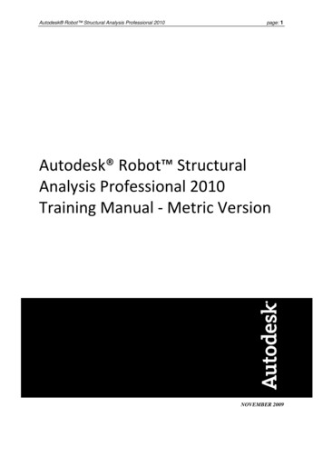
How to build a Robot simulationThis document explains how to build/modify an existing *.mtd file of a basic 6 axis robot simulationfor PowerMill Robot based on the data available from the Robot manufacturer web site (Robot CADdata and data sheet).This document outlines standard procedures and naming conventions that will simplify the processof creating the .mtd file. It is recommended that you follow these accurately.The aim is to build a simulation which represents the robot cell. The position of each axis isimportant. So, before creating a simulation in PowerMill, you must create the robot cell (robot spindle external entities) in PowerShape in the right position. All must match the physical cell. If indoubt, remeasure it using the robot.1. Requirements1.1Geometries (CAD models)It’s easier to work with surfaces or solids to build the robot simulation instead of triangles files.Often, the customer or the robot manufacturer can provide data in this format.An STL model should be used only if it is impossible to get a surface/solid model. This can beexported by the customer using the robot manufacturer simulation software.Spindle6 axis robotExternal Axis(Rotary table)RobotControllerTool changerStatic TableAutodesk PowerMill 2017How to build a Robot simulation 1
1.1.1 Robot CAD model and data sheet1.1.1.1Robot CAD modelCAD data of the robot can usually be found in a surface or solid format. Do not use triangle fileformat (*.stl) when solid/surface are available.The majority of the robot manufacturers allow downloading the CAD of the robot from theirweb site.Where possible, download a STEP file, as often, each axis is a separated solid so there aren’t alot of surfaces to sort out.Example where robot CAD data can be downloaded from (non-exhaustive upport/cad-library/Not available from web site.The website should also have the data sheet of the robot you are looking for, giving you moreinformation about the axes limits, axes length, and other specifications.2 How to build a Robot simulationAutodesk PowerMill 2017
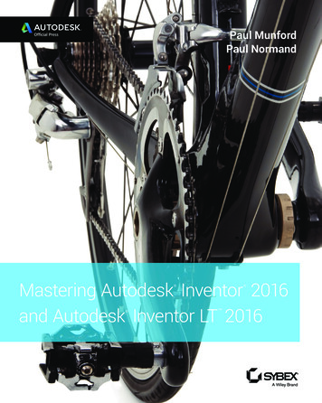
1.1.1.2Robot data sheetSome of the data required for the mtd file, such as the 3D model of the robot arm and the datasheet (containing basic information about the axis rotation directions and the axis limits), may beavailable from the manufacturer website.Below is an example of a robot data sheet that can be found on a robot manufacturer web site.AUTODESK R2 - Model 2017Robot TypeMaximum load (center of gravity)Number of axesController modelPositionRepeatabilityRobot weightAxesAxis 1 (A)Axis 2 (B)Axis 3 (C)Axis 4 (D)Axis 5 (E)Axis 6 (F)Autodesk PowerMill 2017Autodesk R2 - Model 2017185 kg6Autodesk controller 2017/R2Floor / Wall 0.04 mm880 kgRange 185 -50 / 100 - 215 / 70 360 130 720 Speed112 /s89 /s118 /s169 /s212 /s110 /sHow to build a Robot simulation 3
1.1.2 CAD of the spindle (or laser head, welding head, trimmingtool )This CAD is the object which is attached to the 6th axis of the robot. In our case, it’s often aspindle, but it could also be a welding or cladding head, a trimming tool, etc.An STL model should be used only if it is impossible to get a surface/solid model. This can beexported by the customer using the robot manufacturer simulation software.1.1.3 CAD of the External axesThis can be rails or rotary tables, attached or not to the robot.An STL model should be used only if it is impossible to get a surface/solid model. This can beexported by the customer using the robot manufacturer simulation software.1.1.4 CAD of the robot CellThis is everything not linked to the robot and modeling is optional. It contains static objects,such as the cell where the robot is located, the fixtures, and the robot controller. An STL modelshould be used only if it is impossible to get a surface/solid model. This can be exported usingthe robot manufacturer simulation software.4 How to build a Robot simulationAutodesk PowerMill 2017
1.2Coordinates, Workplane and Positions1.2.1 Robot World workplane position & orientationCheck where the robot world workplane is.1.2.2 Robot “Zero position”“Zero position” is the robot’s position when all join angles and/or axes are moved to their 0value. This is also valid for external axes (rails, rotary axes).The robot zero position is different for each robot manufacturer. When you build the simulation,you will have to move the robot to this position.Autodesk PowerMill 2017How to build a Robot simulation 5
1.2.3 Axes directionsCheck the direction of each axis of the robot (external axes too).1.2.4 Axes min/max rangeVerify the minimum and maximum value of each axis.6 How to build a Robot simulationAutodesk PowerMill 2017
1.2.5 Spindle orientationCheck the position of the spindle when the 6th axis is set at its zero position.1.2.6 “Tool attach point” positionBecause the CAD may be inaccurate, the best way to ascertain the tool attach point is tomeasure the “real” coordinates (X, Y, Z) of the tool attach point at the tip of the spindle (in red).One way to get these values is to use a tool and spindle calibration, described in the document:PowerMill Robot - Tool and Spindle Calibration.pptxIt is also important to know the orientation of the tool axis vector (in yellow); this is calculatedby the tool and spindle calibration.Autodesk PowerMill 2017How to build a Robot simulation 7
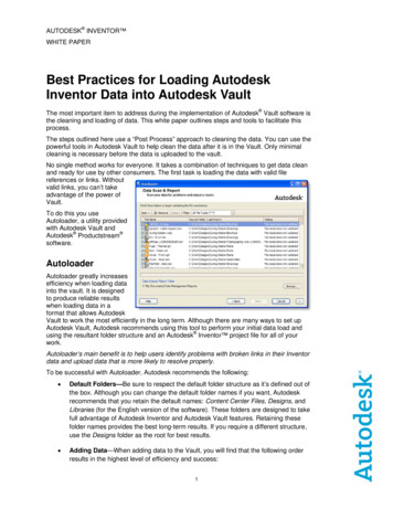
1.2.7 External axis positionCheck the position of the table from the robot origin workplane (X, Y, Z coordinates).1.2.8 Position of the part from the robotYou must accurately know the position of the part from the robot world workplane.ZX8 How to build a Robot simulationYAutodesk PowerMill 2017
2. Preparation ofPowerShapetheCADModelusingAutodesk2.1 Loading and organizing the robot CAD dataThe first step is to load the files downloaded from the web site into PowerShape.If you download a STEP file (if available from web site), often, each robot axis, labels and logoare into a separate solid. In that case, you do not need to organize the CAD model.Some robot manufacturers only provide IGES files that contain only surfaces in a single layer. Inthat case you will need to spend some time in PowerShape, removing unnecessarysurfaces/solids and sorting each axis surfaces/solids into separate PowerShape layers.Note that only the external surfaces of the robot are needed for the simulation and too manysurfaces can have a negative impact on simulation speed.Make sure to use the naming convention as below (see also section 4)AABAB MotorBCBC LogoCDCD MotorDEEFFSpindleNot UsedAutodesk PowerMill 2017How to build a Robot simulation 9
2.2 Moving the robot into positionTo ensure the compatibility of the robot with PowerMill Robot, building a simulation mustfollow certain rules.First, ensure that the robot world workplane is identical to the PowerShape world workplane asdescribed below. If not, move the robot to the right position.Note that the robot world workplane can be different depending on the robot manufacturer.The next step is to move the robot in the position below, even if it is not the zero position of therobot axes.In the majority of the cases you will not have to do this as the robot manufacturer provides therobot in this position already.10 How to build a Robot simulationAutodesk PowerMill 2017
2.3 Importing and positioning of the spindleImport the spindle and move it to the correct position, using the coordinates measured on the“real” robot (or from a spindle calibration), as shown on the picture below:2.4 Importing cell entitiesIf the robot cell contains a table, a controller or some other static entities that you want to seein the robot simulation, you can import or draw them into PowerShape now.Of course, the position must be accurate, as measured on the real robot cell.At this stage, the PowerShape project must match the actual robot and everything must bethere (except the tools).Autodesk PowerMill 2017How to build a Robot simulation 11
3. Export robot entities and its cellEach robot axis, the engines, logos and all entities from the cell, must be exported into separate*.mtd files to be able to simulate them separately and to give them different colours.The *.mtd file contains triangles. The more triangles, the better will the robot simulation look, butthe slower will the simulation and collision checking run.A tolerance value of 0.25mm is a good balance between quality and file size when exporting thedata to *.dmt files. (If the file sizes are still too large or the computer too slow, increase thisvalue).The Triangulation tolerance can be set in Triangle/Mesh page of the PowerShape Options dialog.12 How to build a Robot simulationAutodesk PowerMill 2017
Now export each entity of the robot and its cell into separate *.dmt files.Make sure to use the same naming convention as below:F.dmtCD Motor.dmtEF.dmtDE.dmtBC Logo.dmtCD.dmtAB Motor.dmtBC.dmtAB.dmtA.dmt“A.dmt” can also be called “Base.dmt”The spindle can be exported as “Spindle.dmt”, the table as “Table.dmt” If you are producing .mtd files regularly then PowerShape macros can be used to automate thispart of the process.Autodesk PowerMill 2017How to build a Robot simulation 13
4. PowerMill MTD file4.1 Folder structure4.2 *.mtd file structureThe *.mtd file contains all the information required to control the robot simulation and isspecific to the robot it was created for. The most effective way to create a new *.mtd file is tocopy an existing one and modify it. This process is described on the next page.Here is a description of the *.mtd file structure for a robot holding the tool:Make sure to respect this structure and format (xml format) for a better readability. machine xmlns "x-schema:PowerMillMachineTool" POST "SimPost. " . head attach point PART "head" Coordinates / . table attach point PART "table" Coordinates / . machine part NAME "table" / the part is on the table (floor). machine part List of static entities . /machine part . machine part Robot Axis 1 . machine part Robot Axis 2 . machine part Robot Axis 3 . machine part Robot Axis 4 . machine part Robot Axis 5 . machine part Robot Axis 6 . machine part NAME "head" / the tool is on the head (robot). /machine part . /machine part . /machine part . /machine part . /machine part . /machine part /machine 14 How to build a Robot simulationAutodesk PowerMill 2017
4.3 Modifying an Existing *.mtd FileFrom the PowerMill robot library, load in a robot from the same manufacturer as the robot youare creating a simulation for. Ideally load a robot with a similar configuration (that is, samenumber and type of external axes).From the toolbar at the top of the Robot Library tab select Open Robot Library, and select OpenCurrent Robot Directory.This will take you to the directory containing the *.mtd file for that robot.Select the appropriate *.mtd file from the folder and copy it into the location containing thefolder with the exported CAD models.Rename the *.mtd to give it a descriptive name, this is the name that will appear in the PowerMillRobot library when selecting a robot.Open the file using a text editor such as Notepad .The following values will need to be updated for the new robot:1. The file path for the CAD models. Provided the naming convention was followed when theCAD was exported only the folder name will need to be modified.2. Head attach point.3. Table attach point.4. Axis minimum and maximum values and home positions.5. Centre of rotation definitions. The rotation directions will remain unchanged in mostinstances.Details on how to determine values for these is included in the following pages.Autodesk PowerMill 2017How to build a Robot simulation 15
4.4 Robot simulationA standard robot has 6 axes. Make sure to use the naming convention below (A to F, one letteronly):-Robot Axis 1 is called “A”Robot Axis 2 is called “B”Robot Axis 3 is called “C”Robot Axis 4 is called “D”Robot Axis 5 is called “E”Robot Axis 6 is called “F”-If there are external axes,“T” for a rotary table“X” or “Y” for a linear trackEtc More information about the default settings of a specific robot manufacturer is available in thehelp folder of PowerMill Robot. See files “Robot Setup - xxx.pdf”16 How to build a Robot simulationAutodesk PowerMill 2017
The example below describes the properties of the second axis of the robot. The line numbersare only present to assist with identification of key components.Any subset can be left out of the description, for example the axis definition should not be usedfor static parts and if no CAD model is to be used to represent movement then a model list is notrequired.1)2)3)4)5)6)7)8)9)10)11)12)13)14)15) machine part axis control info ADDRESS "B" MIN "-50" MAX "100" PRIORITY "AUTO" HOME "-30" VALUE "0"/ simple rotary X "327" Y "0.0" Z "916" I "0" J "1" K "0" / /axis model list dmt file path FILE "Robot/BC.dmt" / rgb R "0" G "130" B "255" / /dmt file dmt file path FILE "Robot/BCLogo.dmt" / rgb R "20" G "20" B "20" / /dmt file /model list In this example:Lines 2 to 5 contain all the information required to define the axis:- This robot axis is the second one (starting from the floor) as the name is B.- The minimum rotary angle is -50 .- The maximum rotary angle is 100 .- The priority of this axis is set to AUTO (default value).Priorities can be set as: LOW, MEDIUM, HIGH, AUTO and STATIC.AUTO means that linear axes will move before rotary axes.STATIC means that the axes can be moved manually (for prepositioning) but will not bemoved dynamically by the simulation.- The HOME position of this axis is -30 (position when clicking on the HOME button).- The VALUE of this axis when it was exported from PowerShape was 0 .If the axis position is not 0 at its drawing position in PowerShape (paragraph 3.2), youcan set the value here.- The axis rotates about a line parallel to vector (0, 1, 0) passing through point (327, 0, 916)relative to the robot world work plane. To reverse the direction or rotation reverse thevector direction: (0,1,0) (0,-1,0)Lines 6 through 15 contain the information about the 3D models that move on the axis.- The files “Robot\BC.dmt” and “Robot\BCLogo.dmt” are the CAD files representing thisaxis and are placed in the folder called “Robot”. This folder is in the same file location asthe *.mtd file.- The colour code of the robot axis “BC.dmt” is: Red 0, Green 130, Blue 255.- The colour code of the Logo “BCLogo.dmt” is: Red 20, Green 20, Blue 20.Note: There is no closing statement for the machine part node ( /machine part ); this is becauseall subsequent axes (that is, all axes that are attached and move with this axis) must be definedwithin this machine part. Closing statements for all axes in the robot arm must appear after thedefinition of the 6th axis.Autodesk PowerMill 2017How to build a Robot simulation 17
How to get the XYZ values ( simple rotary X "327.141" Y "0.0" Z "916.1" )?An easy way of knowing these values is by getting the center point of each rotary axis of therobot, from PowerShape.First, make sure the PowerShape world workplane is active:Then, create a circle by three points around the rotary axis:Then, editing this arc will give you the center point coordinate:As this axis rotates around the vector (0,1,0) you do not need to specify the Y coordinate, so theresult becomes: simple rotaryX "327.141" Y "0.0" Z "916.1" I "0" J "1" K "0" / 18 How to build a Robot simulationAutodesk PowerMill 2017
4.5 Tool and Table Attach PointsThe information required to define the attach points for the tool (head) and the part (table) areidentical. Only the process to describe head attach point is described in this document as theprocess can be more complex and often the table attach point will be left at the base of therobot.This describes the position (and orientation) where the tool is attached to the spindle tip.The reference of these coordinates is the robot world workplane. head attach point PART "head" X "1623.52" Y "-1.94" Z "1665.428" I "-0.5" J "0" K "0.866025"U "0.866025" V "0" W "0.5" / The Part definition describes which machine part the tool is going to move with. This mustmatch exactly the name of a machine part defined within the *.mtd file. In the case of a toolmounted on the robot arm, this machine part should be either the robot axis 6 or a machinepart that moves with it.For the table attach point the part should be a machine part that moves with any external axescontrolling part positioning or a static part in the cell. If no external axes are used a static partwill still be required to attach the part to.The red arrow shows the tool attach point position (X "1623.52" Y "-1.94" Z "1665.428")The black arrow describes the tool vector direction (I "-0.5" J "0" K "0.866025")The green arrow defines the direction of the tool workplane X axis (U "0.866025" V "0" W "0.5")Autodesk PowerMill 2017How to build a Robot simulation 19
How to get the XYZ IJK UVW values (X "1623.52" Y "-1.94" Z "1665.428" I "-0.5"J "0" K "0.866025 U "1" V "0" W "0" U "0.866025" V "0" W "0.5")?First, create a line, normal to the spindle face, with its start point on the spindle face and alength of 1mm:End pointStart pointThen, make sure that PowerShape world workplane is active:For the XYZ coordinates, edit the line and use the start point coordinates:To get the vector coordinates, change the “Workspace” to become “Relative”:The end point coordinates will give you the IJK values.20 How to build a Robot simulationAutodesk PowerMill 2017
The UVW vector must be perpendicular to the IJK vector.One method to calculate this vector is to select the vector defining the IJK direction, open theWorkplane menu in PowerShape:and select Workplane Aligned to Geometry:click on either end of the line to create a new workplane.Select the line, open the General Edits menu:and select rotate:Ensure either X or Y is selected as the principle axis:ensuring that you are creating a single copy.and rotate the line 90 ,This new line can be rotated about the z axis of the created workplane to any orientationdepending on the desired orientation of the tool workplane X axis.Delete the created workplane.Double click on the line and change the “Workspace” to “Relative”:The end point coordinates will give you the UVW values. The resulting line in the *.mtd filewill take the form: head attach point PART "head" X "1623.52" Y "-1.925" Z "1665.427"I "-0.5" J "0" K "0.866025" U "0.866025" V "0" W "0.5" / Autodesk PowerMill 2017How to build a Robot simulation 21
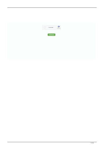
4.6 Creating Linked ConditionsIn simulations it can be useful to be able to simulate axes movements that obey dependentrelationships (that is 2 components that move relative to each other as a result of themovement of other axis components).For example one end of the piston shown below moves with the second axis of the robot whilethe other remains attached to the first axis of the robot.To achieve this a few values need to be determined; the axis and vectors of the movement andthe CAD that will be constrained by this motion these are outlined in the image below.Cylinder attach point:Cylinder.dmtX "-314" Y "0" Z "-10"Piston.dmtPiston attach point:X "65" Y "0" Z "-4"Piston rotation vector:I "0" J "1" K "0"Piston linear direction vector:I "-0.9993" J "0" K "-0.0369"To add this information to the mtd file there are a few key concepts to understand:-The fixed points will move with whichever axes they are defined on in the mtd file.The machine parts for the dependent relationship are defined on the final axis they areattached to (that is, the axis moving with the highest number of other axes).The machine movements and order are determined from the final attach point and workedbackwards.22 How to build a Robot simulationAutodesk PowerMill 2017
In the above example the piston is connected between axes 1 and 2, the mtd file for these axes is listedbelow and a description of the functionality is included below. machine part NAME "RobotAxis1" axis control info ADDRESS "A" MIN "-180" MAX "180" PRIORITY "AUTO" HOME "0"/ simple rotary X "0" Y "0" Z "0" I "0" J "0" K "1" / /axis fixed point NAME "CylinderAttachPoint" X "-314" Y "0.0" Z "-10"/ .Cylinder attach pointdeclaration machine part NAME "RobotAxis2" axis control info ADDRESS "B" MIN "-60" MAX "76" PRIORITY "AUTO" HOME "0"/ simple rotary X "285" Y "0" Z "0" I "0" J "1" K "0" / /axis . machine part NAME "Piston" link rotary X "65" Y "0.0" Z "-4" I "0" J "1" K "0" / /link model list dmt file path FILE "Robot/Piston.dmt" / rgb R "50" G "50" B "50" / /dmt file /model list machine part NAME "Cylinder" link linear I "-0.9993" J "0" K "-0.0369" / fixed point NAME "CylinderAttachPoint " / /link model list dmt file path FILE "Robot/Cylinder.dmt" / rgb R "0" G "73" B "219" / /dmt file /model list Piston attach pointand rotation vectorPiston *.dmt fileCylinder attach pointreference and pistonlinear direction vectorCylinder *.dmt file /machine part /machine part machine part NAME "RobotAxis3" .The cylinder attach point defined above is the point about which the piston assembly rotates onthe first axis. This is defined in the machine part for robot axis 1 as the pivot point will rotateabout axis A, but will not move when robot axis B is jogged.On the second axis we have a new machine part defined called “Piston”. This is separate to themain machine part containers and subsequent axes will not be contained within the definition ofthis part.“Piston” has a link, not an axis, the rotary link allows the piston assembly to rotate freely onrobot axis 2 about the defined rotation centre point and vector to maintain a set of constraints.These constraints are set in the machine part “Cylinder”. The link on this machine part limits themovement of “Cylinder” to a linear motion, relative to “Piston”, to allow the point at the definedfixed point to remain stationary. The linear direction rotates with the “Piston” machine part.Both “Piston” and “Cylinder” machine parts are closed once the definition is complete.Autodesk PowerMill 2017How to build a Robot simulation 23
4.7 Robot cellAll entities attached to the floor and which are not moving must be declared at the beginning ofthe file and are not linked to any axis. machine part NAME "StaticParts" model list dmt file path FILE "Robot/A.dmt" / rgb R "80" G "80" B "80" / /dmt file dmt file path FILE "Robot/Table.dmt" / rgb R "140" G "140" B "140" / /dmt file dmt file path FILE "Robot/Controller.dmt" / rgb R "100" G "100" B "100" / /dmt file dmt file path FILE "Robot/ControllerCables.dmt" / rgb R "0" G "0" B "0" / /dmt file /model list /machine part External axes, such as rotary tables and positioners, are defined using the same text descriptionsand structure as axes on the robot. machine part NAME "PositionerAxis1" axis control info ADDRESS "R" MIN "-90" MAX "90" PRIORITY "STATIC" HOME "0"/ simple rotary X "1660" Y "0.0" Z "550.0" I "1" J "0" K "0" / /axis model list dmt file path FILE "Robot/PositionerAxis1.dmt" / rgb R "80" G "80" B "80" / /dmt file /model list machine part NAME "PositionerAxis2" axis control info ADDRESS "T" MIN "-720" MAX "720" PRIORITY "STATIC" HOME "0"/ simple rotary X "1660" Y "0.0" Z "0.0" I "0" J "0" K "1" / /axis model list dmt file path FILE "Robot/PositionerAxis2.dmt" / rgb R "0" G "130" B "255" / /dmt file /model list machine part NAME "table" / /machine part /machine part 24 How to build a Robot simulationAutodesk PowerMill 2017
Jul 01, 2016 · Autodesk PowerMill 2017 How to build a Robot simulation 9 2. Preparation of the CAD Model using Autodesk PowerShape 2.1 Loading and organizing the robot CAD data The first step is to load the files downloaded from the web site into PowerShape. If you download a STEP file (if availabl