Transcription
Autodesk Robot Structural Analysis Professional 2010page: 1Autodesk Robot StructuralAnalysis Professional 2010Training Manual - Metric VersionNOVEMBER 2009
page: 2Autodesk Robot Structural Analysis Professional 2010 2009 Autodesk, Inc. All Rights Reserved. Except as otherwise permitted by Autodesk, Inc., this publication,or parts thereof, may not be reproduced in any form, by any method, for any purpose.Certain materials included in this publication are reprinted with the permission of the copyright holder.DisclaimerTHIS PUBLICATION AND THE INFORMATION CONTAINED HEREIN IS MADE AVAILABLE BYAUTODESK, INC. "AS IS." AUTODESK, INC. DISCLAIMS ALL WARRANTIES, EITHER EXPRESS ORIMPLIED, INCLUDING BUT NOT LIMITED TO ANY IMPLIED WARRANTIES OFMERCHANTABILITY OR FITNESS FOR A PARTICULAR PURPOSE REGARDING THESEMATERIALS.TrademarksThe following are registered trademarks or trademarks of Autodesk, Inc., in the USA and other countries: 3DEC(design/logo), 3December, 3December.com, 3ds Max, ActiveShapes, Actrix, ADI, Alias, Alias (swirldesign/logo), AliasStudio, Alias Wavefront (design/logo), ATC, AUGI, AutoCAD, AutoCAD LearningAssistance, AutoCAD LT, AutoCAD Simulator, AutoCAD SQL Extension, AutoCAD SQL Interface,Autodesk, Autodesk Envision, Autodesk Insight, Autodesk Intent, Autodesk Inventor, Autodesk Map, AutodeskMapGuide, Autodesk Streamline, AutoLISP, AutoSnap, AutoSketch, AutoTrack, Backdraft, Built withObjectARX (logo), Burn, Buzzsaw, CAiCE, Can You Imagine, Character Studio, Cinestream, Civil 3D,Cleaner, Cleaner Central, ClearScale, Colour Warper, Combustion, Communication Specification,Constructware, Content Explorer, Create what's Next (design/logo), Dancing Baby (image), DesignCenter,Design Doctor, Designer's Toolkit, DesignKids, DesignProf, DesignServer, DesignStudio, Design Studio(design/logo), Design Your World, Design Your World (design/logo), DWF, DWG, DWG (logo), DWGTrueConvert, DWG TrueView, DXF, EditDV, Education by Design, Exposure, Extending the Design Team,FBX, Filmbox, FMDesktop, Freewheel, GDX Driver, Gmax, Heads-up Design, Heidi, HOOPS, HumanIK, idrop, iMOUT, Incinerator, IntroDV, Inventor, Inventor LT, Kaydara, Kaydara (design/logo), LocationLogic,Lustre, Maya, Mechanical Desktop, MotionBuilder, Mudbox, NavisWorks, ObjectARX, ObjectDBX, OpenReality, Opticore, Opticore Opus, PolarSnap, PortfolioWall, Powered with Autodesk Technology,Productstream, ProjectPoint, ProMaterials, Reactor, RealDWG, Real-time Roto, Recognize, Render Queue,Reveal, Revit, Robot, Showcase, ShowMotion, SketchBook, SteeringWheels, StudioTools, Topobase, Toxik,ViewCube, Visual, Visual Bridge, Visual Construction, Visual Drainage, Visual Hydro, Visual Landscape,Visual Roads, Visual Survey, Visual Syllabus, Visual Toolbox, Visual Tugboat, Visual LISP, Voice Reality,Volo, Wiretap, and WiretapCentralThe following are registered trademarks or trademarks of Autodesk Canada Co. in the USA and/or Canada andother countries: Backburner, Discreet, Fire, Flame, Flint, Frost, Inferno, Multi-Master Editing, River, Smoke,Sparks, Stone, and WireAll other brand names, product names or trademarks belong to their respective holders.
Autodesk Robot Structural Analysis Professional 2010page: 3GENERAL INFORMATION. 5SETUP AND PREFERENCES . 5LAYOUT SELECTION . 6CONTEXT MENU . 6DATA AND RESULTS TABLES . 7SNAP SETTINGS . 7DISPLAY OF STRUCTURAL PARAMETERS . 8OBJECT INSPECTOR . 81.REINFORCED CONCRETE DESIGN – 2D FRAME. 91.1 MODEL DEFINITION . 101.1.1 Member Definition . 111.1.2 Library Structure Definition . 121.1.3 Support Definition . 141.1.4 Load Case Definition . 141.1.5 Load Definition for Generated Cases . 151.2 STRUCTURAL ANALYSIS . 161.3 ANALYSIS RESULTS . 171.4 REINFORCED CONCRETE BEAM DESIGN . 181.5 REINFORCED CONCRETE COLUMN DESIGN . 191.6 DESIGN OF MULTIPLE REINFORCED CONCRETE MEMBERS. 212.STEEL DESIGN – 2D FRAME. 232.1 MODEL DEFINITION . 242.2 DEFINITION OF LOAD CASES AND LOADS . 252.3 DEFINITION OF SNOW/WIND LOADS . 262.4 STRUCTURAL ANALYSIS . 272.5 DETAILED ANALYSIS . 272.6 GLOBAL ANALYSIS . 282.7 STEEL DESIGN. 292.8 PRINTOUT COMPOSITION . 323.ELASTO-PLASTIC ANALYSIS . 343.1 MODEL DEFINITION . 343.1.1 Code Selection . 343.1.2 Structural Axis Definition . 353.1.3 Member Definition . 363.1.4 Library Structure Definition . 383.1.5 Auxiliary Node Addition . 393.1.6 Brackets on Bars Definition . 393.1.7 Support Definition . 403.1.8 Definition of Geometrical Imperfections . 403.1.9 Load Case Definition . 413.1.10 Load Definition for Generated Cases . 413.1.11 Snow/Wind Load Generation . 423.1.12 Automatic Code Combinations Generation . 423.2 STRUCTURAL ANALYSIS AND RESULT VERIFICATION . 423.3 ELASTO-PLASTIC ANALYSIS . 433.3.1 Change of Load Case Definitions . 433.3.2 Structural Analysis. 443.3.3 Change of Bar Sections for Elasto-Plastic Analysis . 443.3.4 Structural Analysis and Result Verification . 454.MOVING LOADS - 2D FRAME . 464.1 MODEL DEFINITION . 474.1.1 Member Definition . 474.1.2 Library Structure Definition (a Roof and an Overhead Traveling Crane Beam) . 484.1.3 Support Definition . 504.1.4 Structural Loads Definition . 514.1.5 Moving Load Definition Applied to the Structure . 524.2 STRUCTURAL ANALYSIS . 54
page: 4Autodesk Robot Structural Analysis Professional 20104.3 PRESENTATION OF THE VEHICLE AND THE MOVING LOAD CASE . 544.4 ANALYSIS RESULTS . 554.5 INFLUENCE LINES . 575.MOVING LOAD – 3D FRAME . 595.1 MODEL DEFINITION . 605.2 STRUCTURAL ANALYSIS . 715.3 STEEL DESIGN. 735.4 INFLUENCE LINES . 776.3D STEEL STRUCTURE WITH STEEL CONNECTIONS . 796.1 MODEL DEFINITION . 796.2 STRUCTURE ANALYSIS . 846.3 RESULT ANALYSIS . 846.4 STEEL DESIGN. 856.5 DESIGN OF STEEL CONNECTIONS. 867.3D STEEL FRAME WITH MASSES . 887.1 MODEL DEFINITION . 897.2 CALCULATIONS AND RESULT ANALYSIS . 958.DEFINING AND ANALYZING A CONCRETE FLOOR. 988.1 MODEL DEFINITION . 988.1.1 Contour Definition . 988.1.2 Mesh Definition . 998.1.3 Slab Properties . 998.1.4 Panel and Opening Definition . 1008.1.5 Support Definition . 1008.1.6 Load Case Definition . 1028.1.7 Load Definition for Generated Cases . 1028.1.8 Display of Generated Load Cases . 1048.2 STRUCTURAL ANALYSIS / RESULTS (MAPS ON PANELS CUTS) . 1058.3 CALCULATIONS OF THE REQUIRED (THEORETICAL) REINFORCEMENT AREA . 1088.4. CALCULATIONS OF THE PROVIDED (REAL) REINFORCEMENT AREA . 1109.3D SOLID STRUCTURE . 1129.1 MODEL DEFINITION . 1149.2 STRUCTURAL ANALYSIS . 1279.3 PRESENTATION OF RESULTS IN THE FORM OF MAPS . 12710.SHELL STRUCTURES. 12910.1 SILO . 12910.2 COOLER . 13410.3 PIPELINE . 13610.4 AXISYMMETRIC STRUCTURES . 14011.3D SINGLE-SPAN ROAD BRIDGE WITH A MOVING LOAD . 14511.1 MODEL DEFINITION . 14711.1.1 Structure Geometry Definition. 14711.1.2 Load Definition . 15211.1.3 Definition of the Moving Load Applied to the Bridge Floor . 15611.2 STRUCTURAL ANALYSIS . 15911.2.1 Result Presentation in the Form of Maps . 16011.3 STRUCTURE MEMBER DESIGN . 16111.3.1 Steel Design . 16211.4 TIME HISTORY ANALYSIS. 16912.SECTION DEFINITION . 17412.1 SOLID SECTION. 17412.2 THIN-WALLED SECTION . 176
Autodesk Robot Structural Analysis Professional 2010page: 5General InformationSetup and PreferencesPreferences are available from text menu Tools Preferences. Here are groups of general settingsto customize the look of the user interface and define how the program works. Here you can chooseworking language (language of interface), regional settings (codes, databases) and printout language.All of these are set independently, so you can work with one language (chosen from one of tenavailable) according to different regional codes and print documentation in another.Also within Preferences, you can change look of every particular element of the desktop by usingpredefined templates or by creating your own.Before commencing structure definition, one should set the working language and codes to be appliedin the project as shown in the picture below:Confirm the operation by pressing the Accept button, and then select from the main menu Tools / JobPreferences option. Set the codes and actions as shown below:Job Preferences are grouped in six categories: units, materials, databases, design codes, structureanalysis and work parameters.Autodesk Robot Structural Analysis Professional includes more than 60 sections and materialsdatabases from around the world. With an array of 70 built-in design codes, structural engineers canwork with country-specific section shapes, imperial or metric units, and country-specific building codeswithin the same integrated mode.
page: 6Autodesk Robot Structural Analysis Professional 2010Layout selectionIt is necessary to select appropriate layouts in the process of structure definition. The layouts areaccessible by clicking the list box in the top right corner of the main window which opens the layout listshown in the figure below:Context menuWhile working in the graphical viewer, one may activate the context menu (shown below) by pressingthe right-hand mouse button.The menu allows one to perform many useful (and frequently used) operations while the program iscarrying out the formerly issued commands.
Autodesk Robot Structural Analysis Professional 2010page: 7Data and Results TablesStructure parameters may be modified by means of the relevant tables. The tables relevant to thecurrent layout become visible when one enters the layout. In order to be able to perform global editoperations, one should use the View menu / Tables option from the main menu. There will appear theTables: Data and Results dialog box.In this dialog box, one should indicate the required items and press the OK button. A table containingdata will be generated for each of the indicated items. Once the Edit tab is activated in the bottom leftcorner of a given table, one may perform the operation of modifying structure parameters.Snap settingsThe Snap Settings dialog box becomes available once thelocated in the bottom left corner of the screen).icon is pressed (the first one icon
page: 8Autodesk Robot Structural Analysis Professional 2010Display of Structural ParametersThe Display dialog box becomes accessible once thecorner of the screen) is pressed as shown below.icon (the third one icon in the bottom leftThe available tabs allow one to get access to the data on structure parameters. This option is alsoavailable from the main menu by means of selecting the View menu / Display command.Object InspectorThe Object Inspector is located along the left-hand side of the interface. Using this tool user can Presents the project contents in an organized mannerSelects elements that should be acted upon by a selected commandPresents and modifies properties of project elements (both single elements and wholeobjects)Filters model elementsCreates and manages documentation of a projectThe Object Inspector consists of several topic-specific elements. Tabs to select these topics are alongthe bottom of the dialog.Object Inspector (tabs: Geometry and Groups)Steel Connection InspectorRC Component InspectorInspector - Preparation of Results
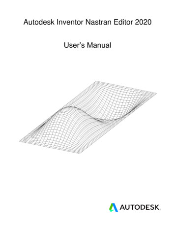
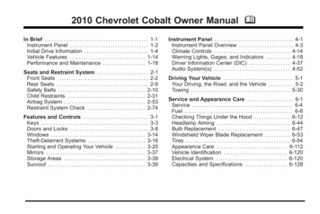
page: 9Autodesk Robot Structural Analysis Professional 2010NOTE:1.In the examples below the following rule has been assumed to indicate definition ofthe beginning and end of a structure bar:for example, (0,0,6) (8,0,6) means that a bar beginning is positioned at a node withthe coordinates as follows x 0.0, y 0.0 and z 6.0 and a bar end - at a node withthe coordinates as follows x 8.0, y 0.0 and z 6.0. The separator (set in theWindows operating system) separates the successive coordinates by using a comma‘,‘ between the values.Reinforced Concrete Design – 2D FrameThis example is used to show the definition, analysis and design of a simple 2D frame illustrated inthe figure below. The frame is made of the RC frame and the truss generated by using the libraryof typical structures available in the RSAP program.Data units: (m) and (kN).Four out of five load cases applied to the structure are displayed in the drawing below.LOAD CASE 2LOAD CASE 3LOAD CASE 4LOAD CASE 5The following rules will apply during structure definition: any icon symbol means that the relevant icon is pressed with the left mouse button, ( x ) stands for selection of the ‘x’ option in the dialog box or entering the ‘x’ value, LMC and RMC - abbreviations for the Left Mouse button Click and the Right Mouse button Click. RSAP - abbreviations for the Autodesk Robot Structural Analysis Professional.To run structure definition start the RSAP program (press the appropriate icon or select the commandfrom the taskbar). The vignette window will be displayed.Select iconin the first row 2D Frame Design).NOTE: The European Section Database (EURO) has been used in this example.
page: 10Autodesk Robot Structural Analysis Professional 20101.1 Model DefinitionPERFORMED OPERATIONSelect the Axis Definition iconfrom the Structural Model toolbar.On the X tab:Position: (0)Number of repetitions: (4)Distance: (6)Numbering: (1, 2, 3 .)DESCRIPTIONStarts definition of structural axes. The Structural Axisdialog box appears on the screen.Defines vertical axis parameters.LMC on the Insert buttonVertical axes have been defined and will be presented inthe Set of Created Axis field.LMC on the Z tabStarts definition of horizontal axis parameters.On the Z tab:Position: (0)Number of Repetitions: (3)Distance: (3)Numbering: (A, B, C .)Defines horizontal axis parameters.LMC on the Insert buttonHorizontal axes have been defined and will be presented inthe Set Of Created Axes field.Apply, CloseCreates defined structural axes and closes the StructuralAxes dialog box. Structural axes will be displayed on thescreen as shown in the figure below.
Autodesk Robot Structural Analysis Professional 2010page: 111.1.1 Member DefinitionSelect the Bar Section iconfrom the Structural Model toolbar.Opens the Sections dialog box.Opens the New Section dialog box.Select theDefinition icon.NewSectionLMC the “I” familyicon, pick(HEB) from the Family List, andselect (HED 240) from the Sectionlist.AddDefines a new section. The section from the Europeansection database (EURO) has been used.LMC in the Section Type field (lowerright corner of dialog box) and selectthe RC beam option.In the Label field enter B 45x60.Under Basic Dimensions, typein fields b (45) cm, h (60) cmAdd, CloseDefines an RC beam section.CloseCloses the Sections dialog box.Opens the Bars dialog box.Select the Bars icon from theStructral Model toolbarLMC on the Bar type field and selectRC columnLMC on the Section field and selectthe type: (C 45x45)Selects bar properties.LMC on the Beginning field(background color changes to green)Starts definition of bars in the structure (structure columns).Enter the following points in theBeginning and End fields.Beginning: (0,0) End: (0,3), AddBeginning; (0,3) End: (0,6), AddDefines the first two bars located on structural axisnumber 1.RMC within the graphics view areaand choose Select command fromthe context menuOpens context menu and switches to selection mode.The mouse cursor changes its shape to “hand”.CTRL ASelects all bars. (Remember to activate the View windowfirst.)Edit menu / Edit / TranslateOpens the Translation dialog box.LMC on the field dX,dZ : (6,0)LMC on the fields:Numbering Increment Nodes: (1)Numbering Increment Elements:(1)Defines the translation vector and numbering incrementfor nodes and bars.
page: 12Autodesk Robot Structural Analysis Professional 2010LMC on the Number of repetitionsfield: (4)Defines the number of repetitions for performed translationoperations.Execute, CloseColumn translation; closes the Translation dialog box.LMC on the Bar type field in theBars dialog box and select RC beamLMC on the Section field and select(B 45x60)Starts definition of beams in the structure and selects theirproperties.LMC on the Beginning field(background color changes to green)Starts definition of bars in the structure.Beginning: (0,3) End: (6,3), AddBeginning: (6,3) End: (12,3), AddBeginning: (12,3) End: (18,3), AddBeginning: (18,3) End: (24,3), AddDefines the RC beam located on the structural axis B.CloseCloses the Bars dialog box.View menu / DisplayOpens the Display dialog box.LMC Bars tabTurn on the Section-Shape option,Apply, OKThis option allows for the display of section shapes for thedefined structure bars. Bars will be displayed on the screenas shown in the figure below.1.1.2 Library Structure DefinitionView menu / DisplayOpens the Display dialog boxLMC Nodes tabTurn on the Node numbers option,Apply, OKThis options allows for the display of node numbers locatedat the ends of the bars.
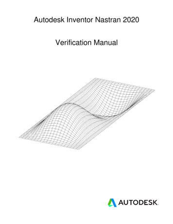
Autodesk Robot Structural Analysis Professional 2010Select the Library Structure iconlocated on the Structure Modeltoolbar.LMC(double-click)onthepage: 13Opens the Typical Structures dialog box and startsdefinition of a library structure.iconSelects a triangular truss of type 1. The Merge Structuredialog box appears and truss parameters can be defined.LMC on the Length L field on theDimensions tab: (24)Defines the truss length (it can also be defined graphicallyin the graphic viewer).LMC on the Height H field: (3)Defines the truss height (it can also be defined graphicallyin the graphic viewer).Defines the number of fields into which the truss will bedivided.LMC on the Number of Fields field:(12)LMC on the Sections tab;To all truss chords (upper and lower)assign (DCED 90x10) and todiagonals, posts asign (CAE 70x7)Assigns the section to the truss bars.LMC on the Insert tabLMC on the Insertion point field,select the node number 3 of thefollowing coordinates: (0,0,6)Defines the truss beginning node.Apply, OKLocates the defined structure in the appropriate place andcloses the Merge structure dialog box. The definedstructure is presented on the drawing below.View menu / DisplayOpens the Display dialog box.
page: 14Autodesk Robot Structural Analysis Professional 2010LMC Nodes tabTurn off the Node numbers optionLMC Structure tabTurn off the Structural axis option,Apply, OKGeometry menu / ReleasesOpens the Releases dialog box.LMC on the Pinned-Fixed releasetypeChooses the release type that will be assigned to a trussbar.LMC on the Current selection field,switch to the graphic viewer andindicate (hover curser over) t
Autodesk Robot Structural Analysis Professional 2010 page: 1 Autodesk Robot Structural Analysis Profession