Transcription
Mach4 CNC ControllerSoftware Installation andConfiguration GuideVersion 1.01 Of 26
Copyright 2014 Newfangled Solutions, Artsoft USA, All Rights ReservedThe following are registered trademarks of Microsoft Corporation: Microsoft, Windows. Anyother trademarks used in this manual are the property of the respective trademark holder.Table of ContentsChapter 1 Introduction to CNC Systems. 4Before You Begin. . 4Introduction . 4Mach4 Layout . 5Chapter 2 Installing Mach4 Software . 6Installation . 6Downloading . 6Installing . 7Run the installer . 7Setting up the Profile . 7Create Shortcut to Profile . 9Chapter 3 Setting up the software . 9Step by step setting up of the machine . 9Plugins and their function . 10Adding and removing Plugins . 10Configuring Plugins . 11Select Motion device . 11Other Plugins . 12Chapter 4 Machine Settings . 122 Of 26
Default Modal State . 12Motor Tuning . 14Counts Per Unit . 15Velocity. 16Acceleration . 17Backlash . 17Reverse. 17Enable Delay . 17Axis Mapping. 18Homing and Limits . 18Home Direction . 18Home Order . 19Home Offset . 19Home Speed. 19Home In Place . 20Soft Enable . 20Soft Max / Soft Min . 20Signals in General . 20Input Signals . 23Output Signals . 24Spindle . 26Max Motor RPM. 26Motor as Spindle . 27Tool Path Settings . 27Machine Limits . 273 Of 26
Chapter 1 Introduction to CNC SystemsThis chapter introduces you to terminology used in the rest of this manual and explains the purposeof the different components in a computer numerically controlled (CNC) system. CNC machines are inmany industries and becoming more popular in manufacturing lines. The traditional machine types areMills, Routers, Lathes and Plasma cutters. The non traditional things that can be done with a CNC systemcan be but not limited it laser measurement, pick and place, quilting, assembly, laser cutting, rapidprototype, painting and so on. Because of the popularity of CNC's in non traditional CNC industriesMach4 has been made to be extremely configurable and expandable. The ability to add and removemodules will be covered in this manual but the screen and scripting customization will be covered inthere respective manuals.Before You Begin.Any machine tool is potentially dangerous. Computer controlled machines are potentially moredangerous than manual ones because, for example, a computer is quite prepared to rotate an 8"unbalanced cast iron four-jaw chuck at 3000 rpm, to plunge a panel-fielding router cutter deep into apiece of oak, or to mill away the clamps holding your work to the table. Because we do not know thedetails of your machine or local conditions we can accept no responsibility for the performance of anymachine or any damage or injury caused by its use. It is your responsibility to ensure that youunderstand the implications of what you design and build and to comply with any legislation and codesof practice applicable to your country or state. If you are in any doubt, be sure to seek guidance from aprofessionally qualified expert rather than risk injury to yourself or to others.IntroductionThis document tells how to install and setup Mach4 motion control software. The foundation ofMach4 is the core called Mach4Core, Mach4Core can be setup in many configurations for the followingmachine configurations general automation, Mill, Router, Lathe, Plasma, Pick and Place, etc. A separatedocuments explain how to operate Mach4 with the specific machine types. The user interface has norelation to the core or motion and/or IO devices used.YOU WILL NEED TO READ THIS DOCUMENTATION! Mach4 is a very complex software package thatcannot be simply made "to work" without proper configuration. The install and play with the settingsapproach may work for other software packages but this is not the case with Mach4. The time spentreading the manual will save many hours of aggravation and will result in a better running machine. Thismanual will give the steps in a logical order that must be followed.4 Of 26
Mach4 LayoutMach4 is built on a central core called Mach4Core.dll and is what connects all the parts of Mach4together. The following diagram (see Drawing 1) shows how all the components are connected:Drawing 1: Mach4LayoutAll IO, Motion and addon devices are plugins allowing them to be setup and configured in Mach4. Theplugins supplied by Newfangled Solutions in the installer are added as appendixes to the end of thisdocument. Any plugins that are not being used should be removed from the system to lower theoverhead of Mach4 on the computer. Development partners of Newfangled Solutions have access toMach4's SDK allowing them to manufacture plugins for other devices and/or functions. The setup,configuration, and any diagnostics will not be covered in this manual for their devices.Chapter 2 Installing Mach4 SoftwareIf Mach4's installer is not on the machine, a copy can be found at www.machsupport.com in thedownloads section of the web page. The machine tool does not need to be connected to the web toinstall Mach4.If the machine is setup by an OEM or manufacture as a complete system, many if not all of the stepsin the following chapter may have already been done for you. The machine settings are all saved in theprofile directory with its own named directory. The named directories can be added and removed fromthe profiles dialog but it is useful to know where the settings are. The named directory for each machinecontains all the machine settings in it's machine.ini file. The machine.ini file is backed up every timemach4 is started so the user can roll back settings if there was an error made during softwareconfiguration. The other directories in the named profile directory contain the macros, tool table, fixturetable, ini backups, screw maps and so on. If a new computer is being setup to replace the an existing PCwith Mach4 a simple copy of the profile named directory can be done to move over all the machinesettings.InstallationMach4 is distributed by Newfangled Solutions over the internet. The software is available as a singleinstaller from the web-page with a download size of about 17MB. After install Mach4 will be in demomode with a limitation of how long Gcode will execute. The time the software can be run in demo isabout 20 min and then it will randomly stop in the middle of a run. Newfangled Solutions recommendsthat Mach4 is setup and tested before purchasing a license. Pricing and options are available atwww.machsupport.com .5 Of 26
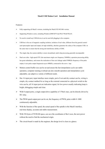
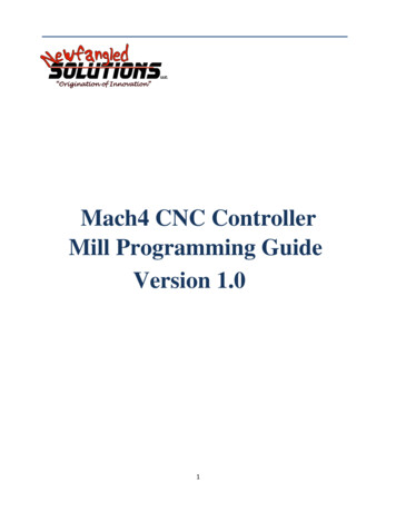
DownloadingDownload the installation package from www.machsupport.com . Click on the download link andsave the self-installing file on the desktop or in a convenient folder. Mach4 needs to be install asadministrator, this can be done by right clicking on the self-installing file and telling it to “Run asAdministrator”. If installing in a remote location the installation file can be saved and moved to amachine that has no web access. The file will require a CD or USB drive to have adequate storagevolume.InstallingThis section will guide the process of installing Mach4 software. If Mach4 has been previouslyinstalled on the machine, Mach4 can be installed on top of a previous installation. There is no need touninstall before reinstalling.If a machine is connected:The machine that is connected to the computer should be set in a condition that will not allowmotion or IO to be triggered. If the machine can be disconnected please disconnect. If the machinecan't be disconnected please press the E-stop button to put the machine into an E-stop condition.Run the installerRunning the installer should be done as Administrator to allow Mach4 to be installed correctly. Thepackage will be installed by default in the C:/Mach4 directory. It is recommended that you keep theinstallation directory as C:/Mach4 so the support staff can better assist you with your future supportneeds. The basic install will load the appropriate files needed for each machine type (Lathe. Mill andPlasma).Setting up the ProfileTo test the installation double click on the Mach4 Icon that was placed on the desktop by the Mach4installer. The icon will launch the MachGUI.exe executable and allow the selection of a profile. It isrecommended that a new profile is setup for the machine that is being configured. A new profile can begenerated by pressing the "Create Profile" button (see Figure 1),but this will create a blank profile. If asimilar setup is available the "Copy Profile" button (see Figure 1) can be used to copy all the profilesettings and create the profile.6 Of 26
Figure 1A "Copy Profile" is very powerful as it will copy all the machine settings such as the tool data, fixturedata, ini backups, Macros, and all machine settings. This can be used later to make a test profile to allowchanges to be made without harming the running machine profile. The profile can be removed aftertesting is finished with the "Delete Profile" button. The profile settings can also be restored to a previoussession if a bad setting has been made. The "Restore Backup" button (see Figure 1) will launch theRestore Backup dialog (see Figure 2). The machine.ini can be selected by looking at the Date and Time ifthe last known running configuration.Create Shortcut to Profile7 Of 26
A shortcut can be created to allow the an immediate launch of the software with a selected profile.By adding the following " /p Mach4Mill" to the end of the target string (see Figure 3) allowsMachGUI.exe to load and immediately load the "Mach4Mill" profile.Fi in the3target string.Any other profile can be loaded by changing the profile name after the /pChapter 3 Setting up the softwareStep by step setting up of the machineIn this section the machine specific settings will be done to transform the software into a functioningmachine controller. The first step was to create a new profile to save the machine settings. This was doneas part of the installation process to protect the machine settings. If this was not done please review the“Setting up the Profile” section of this manual.By the end of this chapter a typical machine should be setup and capable of motion and IO (inputs andoutputs). In order to setup the machine the first step is to install all the plugins that you need for themachine. Examples of plugins that may be needed could be Parallel Port and Modbus.Note: If the software is locked the configuration settings may not be available. If the software is lockednon of the configuration dialogs will be available.8 Of 26
Plugins and their functionThe plugins in Mach4 are the building blocks of the system. The plugins all use the Mach4core.dll as abase but have the power to add functionality to the system. Plugins can perform the following functionsScipting, Motion, IO, File conversions, File loading, Motion Generation and countless other functions.The ability to add such functionality is fundamental in the setup of the machine. The most importantplugin is the motion control plugin. A careful selection of plugins needs to be done to add theappropriate functionality for the machine to be configured.Adding and removing PluginsTo add a plugin from a plugin archive file m4plugw for windows, m4plugl for linux, and m4plugm formac. To load a plugin archive navigate to the "Configure Plugin" Dialog (see Figure 5) by navigatingConfigure/Plugins (see Figure 4)Fi4A plugin must be enabled to allow the plugin to function. The software must be restarted after enablingor disabling to allow the plugin function to change its state. To remove a plugin highlight the row of theplugin and press the "Remove" button (see Figure 5).Configuring PluginsThe configuration of the plugins can be done from the "Configure Plugins" dialog (see Figure 5). Notall plugins can be configured as they have no settings that can be customized. For the plugins that can beconfigured a "configure" plugin button is available to the right of the pugin description. When theconfigure button is pressed it will launch the configuration dialog supplied by the Plugin author. Theconfiguration of the device must be done before the devices IO can be accessed or used by Mach4. Theconfiguration of the plugins incorporated in the installer will be covered in appendixes to this document.9 Of 26
Figure 5Select Motion deviceThe first device that needs to be setup is the motion device. To select the device go to"Configure/Select Motion Dev." (see Figure 4). The "Select Motion Device " dialog (see Figure 6) allowsthe appropriate motion device to be selected. The selected motion device tells the core what device candrive the motors and the high speed IO. The all other motion devices are set to be deactivated and willnot allow the IO or motion to be controlled. The system must be restarted after motion device has beenselected to allow the motion device plugin to do its startup initialization. After the restart the motiondevice needs to be configured. To configure the motion device please use the Motion device suppliedmanual and continue setting up the software once it is complete.10 Of 26
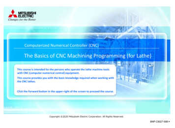
Figure 6Other PluginsThe rest of the IO devices can be setup at this time if the settings are known. Some plugins that arenot fundamental to the machine can be setup at a later time. It is the responsibility of the installer todetermine what is needed to get the machine running. An example of a plugin that would need to besetup and configured would be if a PLC was installed to enable the servo amps and machine. In this caseno testing can be done without Modbus communication to the PLC. To many machine configurations canbe done for this manual to take them into account so careful planning on the part of the installer is theonly way to get a system setup.Chapter 4 Machine SettingsDefault Modal StateThe default state of the software is set at start-up or when the reset button is pressed. The followingoptions can be set and should only be set once. If the CV mode or some other setting needs to bechanged in a Gcode or for a short period of time, MDI should be used. The configuration dialogs are onlyused for setting the start up stateAll configuration settings can be found in the "Mach Configuration" dialog (see Figure 7). The following isa description of the settings that can be changed in the dialog (see Table 1).11 Of 26
SettingUnits ModeTraverse ModeMotion ModeLook Ahead LinesDistance ModeArc Center ModeFeed ModeActive PlaneCycle RetractSpindle ModeInitialization CodesCoolant DelayMist DelayJog IncrementsGcode FileExtensionsInclude Commentsin MessageDeref Axis In EstopCycle Stop isControlled StopDescriptionInch G20 / G21 Millimeters, The default units the machine is setup in such asRapid G00 / Feed G01Exact Stop G61 / Constant Velocity G64Number of lines the interpreter can chain together to get to the programmedFeedrateAbsolute G90 / Incremental G91, Distance mode used by defaultAbsolute G90.1 / Incremental G91.1, Distance mode for the IJK circle centers. Rtype centers are not effected.Feed Per Rev G95 / Feed Per Min G94, feed mode used by linear and arc feedmoved. Feed per rev must have true spindle RPM to be used.XY Plane G17 / XZ Plane G18 / YZ Plane G19, The plane selection used for Drillcycles, Arcs and cutter compInitial Z G98 / Rapid Plane G99, Selects the can cycle position for the moves inthe working axis. The working axis is perpendicular to the current active plane.Constant RPM G97 / Constance surface Speed G96, Selects the default spindlespeed mode.The init codes are run when the program starts and also when the reset ispressedTime to wait for the Coolant to turn onTime to wait for the Mist to turn onIncrements used for Incjog registerThe Gcode extensions for files to be executed. This sets the open able extensionsof the file open dialog.Enabling the selection will add all comments in the Gcode file to the messageslog.Enabling sets the axis homing to be false when in E-stop is activeEnabling will set the axis to do a controlled deceleration when a Cycle Stop iscommanded. A very slight delay will be seen as the axis comes to a stop.Table 1: General Settings12 Of 26
Figure 7Motor TuningMotor tuning is one of the most important settings in configuring a machine. The settings available inthe motor tuning dialog (see Figure 8) will allow the motor to be setup for the appropriate Counts perUnit, Max Velocity, Acceleration, Backlash, Direction Reversal and delay for enable signal. A detailedFigure 8description of each of the settings will be given in the following section.13 Of 26
Counts Per UnitThe Counts Per Unit is used to convert the users units (Inches, Millimeters, Degrees,etc.) intoencoder counts or step pulses depending on the type of system. The counts per unit is a value that canbe found with mathematics. The value should never be “tuned” or “adjusted” because it is amathematical relationship with the drives, screw pitch, reduction ratio and so on. The followingexamples will show how this value can be calculated:Example 1: CNC Router with rack and pinion driveStepper Motor with 2000 Steps per RevBelt Reduction (Small Pulley 15 teeth(Input Gear), Large Pulley is 40 teeth(Output Gear))Pitch Ratio of the Pinion gear is .765 “𝑂𝑂𝑂𝑂𝑂𝑂𝑂𝑂𝑂𝑂) ���𝐼𝐼𝐼𝐼𝐼𝐼𝐼 �𝑃𝑃𝑃𝑃ℎ𝐷𝐷𝐷15(40) 2000 𝐶𝐶ℎ. 765Example 2: CNC Lathe with a lead screwLead of screw .25 inch Per RevBelt Reduction 15 tooth (Input Gear), 30 tooth (Output Gear)Servo drive with 5000 encoder counts per ��𝐼𝐼𝐼𝐼𝐼𝐼𝐼 ) ��𝑝𝑝𝑝𝑝𝑝 �𝑆𝑆𝑆𝑆𝑆𝑆𝑆𝑆𝑆ℎ15(30) 5000 𝐶ℎ. 25As a rule of thumb an inch machine should have the steps per unit greater then 5000 (200 for MM). Avalue of 5000 will give a resolution of .0002 inches. A greater number of steps per unit will give betterperformance as well as finer resolution. The only issue with a very high count per unit is that the maxvelocity can become limited. The motion controller may only be able do deal with a limited number ofcounts or steps per sec. Please check your motion controllers documentation to see get the maxfrequency of the motors. If you would like to predict the max frequency this can also be done ��𝑀𝑀 �� ��𝑂𝑂60In the next examples we will consider the max velocity to be 200 Inches per minute40,000 counts per unit200 40,00060 133,333.333𝐻𝐻 133.33kHz14 Of 26
6971.67756 counts per unit200 6971.6775660 23,238.93𝐻𝐻 32.24𝑘𝑘𝑘VelocityThe Velocity in the dialog is the maximum rate in units per min. This is also the velocity that will beused for rapid moves when running Gcode.Setting a Stepper:On a stepper machine to set the max velocity a series of test need to be made. The Steps per Unitmust be set before the axis can be tested. Set a value of a max velocity that seems to be reasonable andtest with a jog at 100% jog rate. If the axis is able to move without missing steps (most times you willhear a “buzzing” or “squealing” sound when steps are missed, repeat this process until the upper limit isfound. Once the max velocity is found the max velocity should then be set to 20% - 30% less. To insurethat there are no missed steps during motion.Setting a Servo:To set the max velocity of a servo machine a small series of tests can be preformed or it can be donemathematically with some calculations. When testing the max rate of a servo and the max velocity isexceeded the servo may fault from being out of position (digital servo) or will not get to max velocity andmake an abrupt stop. If ether one of the following happen the velocity must be lowered until thebehavior is fixed. Once the motor is fixed the velocity should be lowered by 5% to insure that the bestperformance can be obtained.AccelerationThe max acceleration sets how quickly the motor can get to speed. The higher the acceleration thefaster the cutting can be done. The higher the acceleration the quicker an axis can reverse and go aroundcorners. Cycle times can be lowered by running higher accelerations and lowering the max velocity. Theacceleration should not be raised to the point that it causes motor stalling, vibration in the frame, orother unwanted vibration.BacklashBacklash is used to take out mechanical wind up in the drive system. The misconception is thatbacklash can be used to fix “slop” in a screw/ ball-nut or slop in a rack and pinion. This can be used tohelp fix the machine but is not the proper way to correct the problem. The only way to truly fix the issueis to fix the mechanical issue. The backlash should never exceed .005 inches or .1 mm .15 Of 26
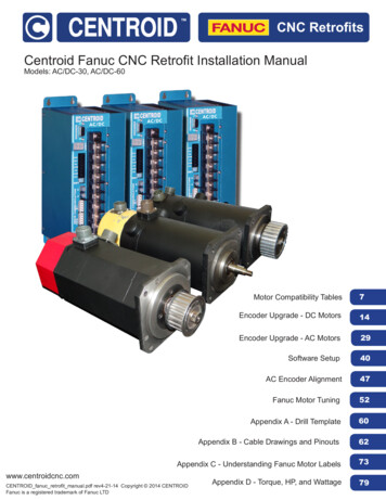
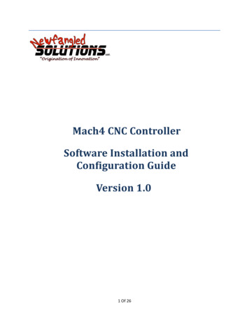
ReverseThe reverse section is used to reverse the motion of the motor.Enable DelayEnable delay will allow a the enable signals to turn on with a delay. The delay can be used to stage theenabling of the amps. This can be used to lower the inrush current by enabling the amps one by one.Axis MappingThe axis mapping dialog (see Figure 9) is used to set what motors are used for an axis as well as thehoming order and max limits for the axis. The motors can be assigned to an axis with a maximum of 6motors per axis. The axis will use the lowest max velocity and the lowest acceleration. This is done toalow slave motors to not have the same motor settings as the other motors associated to he axis. Thesteps per unit also do not need to be the same for each motor that is part of the axis.Figure 9Homing and LimitsSetting the homing and limits will set what the machine will do when the machine enters a homestate or reaches a limit. The act of homing is fundamental in the operation of CNC's and automatedequipment. Homing the machine will set the machine zero position of the motors. This will be the basefrom with all work / fixture offsets are calculated from. All the settings for the homing of the axis aredone in the Homing and Limits dialog (see Figure 10).16 Of 26
Home DirectionThis sets the direction to home the axis (see Figure 10). Pos for homing in the positive direction Negfor homing in the negative direction.Home OrderThe sequence the axis home in can be controlled by setting the “Home Order” (see Figure 10). Thefirst axis to home will be axis with the number 0 and then subsequent axis will home with the nextgreatest home order value. For example if you would like to home the Z axis first then the X and Y at thesame time the values would be as follows:X 2Y 2Z 1Figure 10Home OffsetThe home offset allows for a shift from the home switch position(see Figure 10). This can be used toto shift the home position if the home switch is not located at the end of travel.17 Of 26
Home SpeedThe home speed is the rate the machine moves to detect the home switch (see Figure 10). The homeswitch will set the machine zero position with the addition of any home offset. The Home Speed is set asa percentage of the max velocity of the axis. Example :MaxVel 200 Units Per MinHomeSpeed 20%𝐻𝐻𝐻𝐻𝐻𝐻𝐻𝐻𝐻) 𝑀𝑀𝑀𝑀𝑀 (10020) 40𝑈𝑈𝑈𝑈𝑈𝑈𝑈𝑈𝑈𝑈𝑈200 (100Home In PlaceThe Home in Place selection tells the axis to set the machine zero where it is when a home axis isrequested (see Figure 10). This feature is used on machines that have no home switches or an axis thathas no home switch. On a machine with no home switches the axis can be moved to the end of thetravel and lined up with an indicator mark. With the machine at the home position the home can betriggered for that axis setting the machine position. This will allow the softlimits to be used and fixtureoffsets.Soft EnableThe state of the Soft Enable tells the core if the axis should be checked against the upper and lowersoft limits (see Figure 10). With the soft limits active the axis will decelerate to the Max or Min limit if itis jogging and will prevent any incremental jogs past the limits. When running Gcode any moves pannedpast the limits will not be done and the machine will be put into a stop condition and a soft limit errorwill be displayed.Soft Max / Soft MinThe max and min settings are the most positive and negative machine positions for the axis (seeF
recommended that a new profile is setup for the machine that is being configured. A new profile can be generated by pressing the "Create Profile" button (see Figure 1),but this will create a blank profile. If a similar setup is available the "Copy Profile" button (see Figure 1) can be used