Transcription
Mach4 CNC ControllerMill Programming GuideVersion 1.01
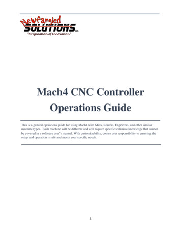
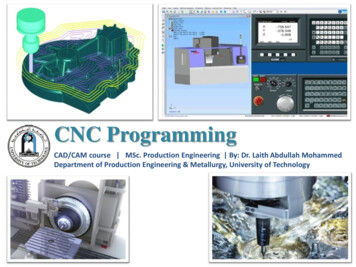
Copyright 2014 Newfangled Solutions, Artsoft USA, All Rights ReservedThe following are registered trademarks of Microsoft Corporation: Microsoft, Windows. Any othertrademarks used in this manual are the property of the respective trademark holder.Table of ContentsChapter 1: Introduction . 2Glossary . 3Format . 4Chapter 2: G Code List. 5G Code Descriptions and Examples. 7Chapter 3: Canned Cycles . 33Drilling . 35Tapping. 40Boring . 43Chapter 4: Cutter Compensation . 50Chapter 5: M Code List. 56M Code Descriptions . 56Chapter 1: IntroductionG Code is a special programming language that is interpreted by Computer Numerical Control (CNC)machines to create motion and other tasks. It is a language that can be quite complex at times and canvary from machine to machine. The basics, however, are much simpler than it first appears and for themost part follows an industry adopted standard. Mach4 has made a large leap closer to this standard.An important point to remember when reading this manual: In describing motion of a machine it willalways be described as tool movement relative to the work piece. In many machines the work piece willmove in more axes than the tool; however the program will always define tool movement around thework piece. Axes directions follow the right hand rule, see figure A.2
Figure A: Right hand ruleGlossaryBlockCanned ordGMX, Y, Z, A, B, CSTHDFPA single line of G CodeComplex cycle defined by a single block of codeProgram pause with a duration defined by “P” in secondsEnd of block. Required at the end of every block of G Code. In Mach4 this is acarriage returnVelocity, set by F, at which an axis will moveCollection of G codes that control the same function or mode, i.e. G90 and G91positioning modesActive until a code from the same group is calledA line perpendicular to a plane, pointing in the positive direction.Point in a coordinate system where X, Y and Z are zeroRevolutions per minuteUnits per minute (inches, millimeters, degrees, etc)A single word of G Code is a letter followed by a number. G01, X1.0, etc. are wordsPreparatory function, G followed by a numerical code, specifies machining modesand functionsMiscellaneous function, M followed by a numerical code, defines program flow andcan control auxiliary functions such as coolant. Can also perform machine specificfunctions and macros user or builder.Movement commands followed by a numerical value, define the end point of amotion commandSpindle speed, followed by numerical value of desired rpm or surface speedTool call, followed by next tool number to be usedTool height offset to be used, generally matches the tool numberTool diameter offset to be used, generally matches the tool numberFollowed by a numerical value to define the feedrate. The magnitude and value ofwhich will be determined by the feed mode settingFollowed by a numerical value, specifies dwell time in seconds. (also used in otherfunctions)3
NSequence numbers. Used for program organization and go to commandsFormatIn writing G Code programs there are some rules to be aware of as well as some general formattingguidelines that should be followed or at least considered.The first part of any program should be a safe start up block. This line of code is used to make sure thatsome modes are disabled and others are set to their most common setting. An example safe start blockwould look like this:G00 G90 G17 G54 G40 G49 G80This block of code tells the machine that we want to be in rapid mode and using absolute position in theXY plane of fixture offset 1. At the same time we want to cancel any tool diameter and length offsetsand make sure any active canned cycles are cancelled.G00 – Rapid modeG90 – Absolute position modeG17 – XY plane selectG54 – Fixture offset 1G40 – Cutter compensation (tool diameter) cancelG49 – Length offset cancelG80 – Canned cycle cancelIt is recommended that this safe start block be used at the start of the program and also before orimmediately following every tool change. It is common to restart a program from a tool change, havingthe safe start line there can greatly reduce the chance of a machine not acting as expected, the resultsof which can be aggravating at best and a crash at worst. The safe start block shown here is just anexample. Every machine and every programmer are a little different and each will have their own startup block.Jumping to the end of the program there is not a lot required. Typically there will be a couple blocks ofcode to return the Z axis to the home position and maybe move the work piece closer to the operatorfor easier loading and unloading of parts. Shutting off the spindle and coolant or any other accessoriesis also a good idea here. The final block in a program is a program end code, most commonly M30 butthere are other options. Make sure this final block is followed by an end of block. It is easy to forget thislast EOB in a program for Mach because it is just a carriage return and not always readily apparent. Oneway to make sure that there is always an EOB on your program end block is to follow it with %. Like this:.M304
%This percent sign is a familiar symbol to CNC programmers in industry; however any symbol or charactercan be used as it will not be read by the control because of the program end before it. If there is no EOBfollowing the percent sign it will not show up in the program when loaded into Mach.In between the start and end is the body of the program. There are a few rules here. Each block of codewill contain a combination of words. Multiple G codes can be specified in a single block, however ifmore than one from the same modal group is specified the last one in the block will be valid, with theexception of group 00. Modal G codes stay active until another from the same group is called. Forexample; G01 is modal so it is not necessary to put it in consecutive blocks. Once active every successivepositioning block will be in the G1 mode unless another code from group one is called (G00, G02, G03,etc.). All G codes not in group 0 behave this way.Only one M code can be specified in a single block. Same holds true for all other words.Generally leading zeroes are not required in G Code. For example G01 and G1 are the same. The sameholds true for M codes, position commands, feedrates, etc. When specifying values for position,feedrate, variables, etc., it is good practice to always use a decimal point and trailing zero, instead of X1use X1.0. Although the decimal point is not required (in Mach X1 X1.0) it is HIGHLY recommended.Chapter 2: G Code pid MoveLinear Feed MoveClockwise Arc Feed MoveCounter Clockwise Arc Feed MoveDwellExact stopFixture and Tool Offset SettingClockwise CircleCounter Clockwise CirclePolar Coordinate CancelPolar CoordinateXY Plane SelectZX Plane SelectYZ Plane SelectInchMillimeterZero Return2nd, 3rd, 4th Zero 1517171718181820
2121201313015151616161616161616161616161616Probe functionThreading*Cutter Compensation CancelCutter Compensation LeftCutter Compensation RightTool Length Offset EnableTool Length Offset - EnableTool Length Offset CancelCancel ScalingScale AxesLocal Coordinate System ShiftMachine Coordinate SystemFixture Offset 1Additional Fixture OffsetsFixture Offset 2Fixture Offset 3Fixture Offset 4Fixture Offset 5Fixture Offset 6Unidirectional ApproachExact Stop ModeCutting Mode (Constant Velocity)Macro CallMacro Modal CallMacro Modal Call CancelCoordinate System RotationCoordinate System Rotation CancelHigh Speed Peck DrillingLH Tapping*Fine Boring*Canned Cycle CancelHole DrillingSpot FaceDeep Hole Peck DrillingRH TappingRH Rigid Tapping*LH Rigid Tapping*Boring, Retract at Feed, Spindle OnBoring, Retract at Rapid, Spindle OffBack Boring*Boring, Manual 6283942433535373840424244454648
G8916Boring, Dwell, Retract at Feed, Spindle OnG903Absolute Position ModeG90.14Arc Center Absolute ModeG913Incremental Position ModeG91.14Arc Center Incremental ModeG920Local Coordinate System SettingG92.10Local Coordinate System CancelG935Inverse Time FeedG945Feed per MinuteG955Feed per Revolution*G9614Constant Surface Speed*G9714Constant SpeedG9810Initial Point ReturnG9910R Point Return* Implementation based on machine and control 23233G Code Descriptions and ExamplesNote:For clarity rotational moves have been omitted from this manual.All motion commands can also contain A, B, and/or C axis motion.G00 – Rapid move: Rapid moves are used to move from point to point in free space, not cuttingmaterial. These moves do not require a feed rate input as they take place at max velocity of themachine. In absolute position mode (G90) X, Y and Z define the end point of the move in the usercoordinate system. In incremental position mode (G91) X, Y and Z define the distance and direction tomove from the current position.Format: G00 X Y ZExample: Program a rapid move to X1.0, Y3.0G0 G90 G54 G17 G40 G49 G80T1 M6S2500 M3G0 X1.0 Y3.0M30Safe start lineTool changeStart spindleRapid to XY positionProgram end and rewindG01 – Linear Feed Move: Linear feed moves are point to point moves in a straight line at a federatespecified by F. The moves are interpolated so all axes in motion reach the end point at the same time.In absolute position mode (G90) X, Y and Z define the end point of the move in the user coordinatesystem. In incremental position mode (G91) X, Y and Z define the distance and direction to move fromthe current position.7
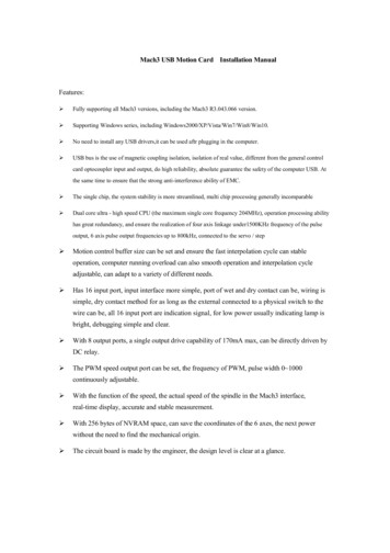
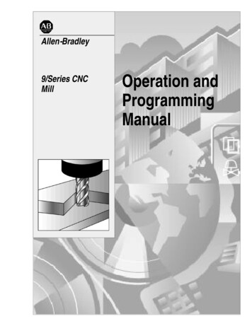
Format: G01 X Y Z F .Example: Program a feed move from X1, Y3, to X10, Y-1 at a feedrate of 15 UPM.G0 G90 G54 G17 G40 G49 G80T1 M6S2500 M3G94G0 X1.0 Y3.0G1 X10.0 Y-1.0 F15.0M30Safe start lineTool changeStart spindleFeed per minute modeRapid to XY positionMove to XY position at feedrateProgram end and rewindG02/G03 – Arc Feed Move: Used to cut an arc at a federate specified by F. An arc is defined by its startand end points, its radius or center point, a direction, and a plane. Direction is determined by G02,clockwise, and G03, counterclockwise, when viewed from the plane’s positive direction (If XY plane isselected look down so that the X axis positive direction is pointing to the right, and the Y axis positivedirection is pointing forward). See figure 2-1 for a graphic representation of the motion of a G02. Thestart point is the current position of the machine. Specify the end point with X, Y, and Z. The valuesinput for the end point will depend on the current G90/G91 (abs/inc) setting of the machine. Only thetwo points in the current plane are required for an arc. Adding in the third point will create a helicalinterpolation.Next is to specify the radius or the center point of the arc, only one or the other, not both. To specify the radius, use R and input the actual radius of the desired arc, see Format 2. Whenan arc is created knowing only start and end points and a radius there are two possiblesolutions, an arc with a sweep less than 180 and one with sweep greater than 180 . The sign ofthe radius value, positive or negative, determines which arc will be cut, see figure 2-2. Apositive value for R cuts an arc with sweep less than 180 . A negative value for R cuts an arcwith sweep greater than 180 .A more accurate and reliable way to define an arc is by specifying the center point, this is donewith arguments I, J, and K, see Format 1. The center point must be defined in the current plane.I, J, and K correspond to X, Y, Z respectively; the current plane selection will determine whichtwo are used. XY plane (G17) would use I and J for example. Mach has two settings for how I, J,and K should be specified, absolute and incremental. This setting can be changed by G code,G90.1 and G91.1, or in the general tab in the Mach configuration. This setting is independent ofthe G90/G91 setting. If arc center mode is set to incremental then I, J, K are the distance anddirection from the start point to the center point of the arc. If arc center mode is set to absolutethen I, J, K are the absolute position of the arc center point in the current user coordinatesystem.Format 1: (G17) G02/03 X Y I J F(G18) G02/03 X Z I K F8
(G19) G02/03 Y Z J K FFormat 2: (G17) G02/03 X Y R F(G18) G02/03 X Z R F(G19) G02/03 Y Z R FStartPointI (Inc)YWorkZeroXI (Abs)J (Inc)J (Abs)RFigure 2-1: Path of tool point in circular and helical interpolation (G02).-RStart Point REnd PointStart PointFigure 2-2: Difference between negative and positive values for R9End Point
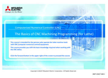
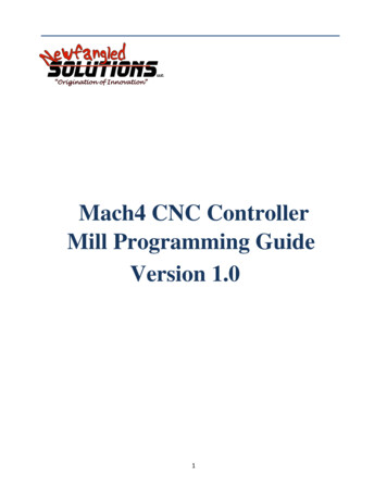
Example: Program an arc centered at 1.0, 0.0 in the XY plane with radius 2. Start point at 3.0,0.0 andsweep 90 degrees counter clockwise. Feedrate 10 UPM. (Arc center mode set to incremental)Format 1:G0 G90 G54 G17 G40 G49 G80T1 M6S2500 M3G0 X3.0 Y0.0G43 H1 Z.5G94G1 Z0.0 F10.0G3 X1.0 Y2.0 I-2.0 J0.0 F10.0G0 Z.5G0 G53 Z0.0M30Safe start lineTool changeStart spindlePosition to X and Y start pointActivate tool offset 1 and move to Z rapid planeFeed per minute modeZ plunge at feedrateArc moveRetract Z to rapid planeReturn Z to homeProgram end and rewindFormat 2:G0 G90 G54 G17 G40 G49 G80T1 M6S2500 M3G0 X3.0 Y0.0G43 H1 Z.5G94G1 Z0.0 F10.0G3 X1.0 Y2.0 R2.0 F10.0G0 Z.5G0 G53 Z0.0M30Safe start lineTool changeStart spindlePosition to X and Y start pointActivate tool offset 1 and move to Z rapid planeFeed per minute modeZ plunge at feedrateArc moveRetract Z to rapid planeReturn Z to homeProgram end and rewindA helical interpolation is defined very similar to an arc. The only difference is the addition of the thirdcoordinate of the end point. This third coordinate will define the height of the helix. See the followingformat for what this looks like in the XY plane:Format 1: (G17) G02/03 X Y Z I J FFormat 2: (G17) G02/03 X Y Z R FExample: Program a helix with radius 1.0 and center point 0.0, 0.0 in the X,Y plane, start point 0.0, .5,height 1.0 with initial Z at 0.0. Feedrate 10 UPM. Arc sweep should be 270 clockwise. See figure 2-2for the tool path.G0 G90 G54 G17 G40 G49 G80T1 M6S2500 M3G0 X0.0 Y.5G43 H1 Z.5G94Safe start lineTool changeStart spindlePosition to X and Y start pointActivate tool offset 1 and move to Z rapid planeFeed per minute mode10
G1 Z0.0 F10.0G2 X-.5 Y0.0 Z-1.0 I0.0 J-.5 F10.0G0 Z.5G0 G53 Z0.0M30Z plunge at feedrateHelical interpolationRetract Z to rapid planeReturn Z to homeProgram end and rewindFigure 2-2: Helical interpolation example toolpathG04 – Dwell: A dwell is simply a pause in the program. The duration of the dwell is specified by P inseconds. No machine movement will take place during a dwell. No auxiliary codes will be turned off, i.e.if the spindle is on it will stay on, coolant will stay on, etc.Format: G04 PExample: Program a 5 second dwell after positioning to X1.0, Y1.0, Z.5.G0 G90 G54 G17 G40 G49 G80T1 M6S2500 M3G0 X1.0 Y1.0Z.5G4 P5.M30Safe start lineTool changeStart spindleRapid to XY positionRapid to Z positionDwell for 5 secondsProgram end and rewindG09 – Exact Stop: G09 is a non modal exact stop. Machine accelerations cause corners to be slightlyrounded; when a true sharp corner is required G09 should be used. Although similar to G61 in function,G09 is not modal while G61 is. When G09 is included in a movement block, axis motion is decelerated tothe end point of motion and the position is checked to be exactly as specified. This position check at the11
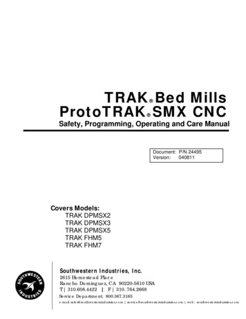
end of the move ensures that the machine actually reaches the desired position before moving onto thenext blockFormat: G01 G09 X Y FExample: Program a 2.0 inch square centered at X0.0, Y0.0 with true sharp corners at X1.0, Y1.0 and X1.0, Y-1.0, feedrate 15.0 UPMG0 G90 G54 G17 G40 G49 G80T1 M6S2500 M3G94G0 X-1.0 Y1.0G1 G9 X1.0 F15.0Y-1.0G9 X-1.0Y1.0M30Safe start lineTool changeStart spindleFeed per minute modeRapid to XY positionMove to position at feedrate, exact stop activeMove to position at feedrateMove to position at feedrate, exact stop activeMove to position at feedrateProgram end and rewindFigure 9-1 shows what this square would look like, slightly exaggerated.With ExactStopWithoutExact StopFigure 9-1: Square with exact stop on two cornersG10 – Fixture and Tool Offset Setting: It is possible to set fixture and tool offsets in the program. Thiscan be very useful for programming multiple fixtures that have known zero points, multi palletmachines, applying automatic compensation of tool wear, and many other situations that requirechanging offset values. G10 is also one of the least understood G codes and is therefore underutilized.12
Changing offset values in a program requires a bit of cautiousness, a mistake can easily result in ruinedparts and damaged tools. When used properly however, G10 can add flexibility and safety to a programand machine, especially with automation and lights out capacity or inexperienced operators.Starting with fixture offset setting the G10 block will look like the following:Format: G10 L2 P X Y Z A B CL selects the function of the G10 block, different values will have different functions. L2 is thedesignation for fixture offset setting. The value of P specifies which offset is being set. For the basic 6fixture offsets P values are as follows:Fixture offset (G )545556575859P123456The data for the fixture offset is set by X, Y, Z, A, B, C.XYZABCX axis offsetY axis offsetZ axis offsetA axis offsetB axis offsetC axis offsetAll values do not need to be specified, only the ones to be set. If, for example, a Z is not programmed itsimply will not be changed in the fixture offset.In G90, absolute, mode the values in the G10 line will be directly input into the fixture offset. When inG91, incremental, mode the values will be added to the desired fixture offset. This is a major differencein functionality and care should be taken to make sure the right mode is active for the desired effect.Example: Set G56 fixture offset to X-8.0, Y-3.0, Z-5.0, A45.0 in a program.G0 G90 G54 G17 G40 G49 G80G10 L2 P3 X-8.0 Y-3.0 Z-5.0 A45.0M30Safe start lineSet G56 fixture offset valuesProgram end and rewindAdditional fixture offsets, G54.1 Pxx, can also be set using G10. Setting of these offsets is the same,except it is done using L20. The legacy additional fixture offsets (see fixture offset section of this manualfor more details) can still be set with G10. The following table shows the additional fixture offset P13
number and its corresponding G10 P number as well as the legacy offsets. Note that G54.1 P1 is thesame offset as G59 P7, so G10 L20 P1 and G10 L2 P7 both set the same offset values.G54.1 P123248G10 L20 P123248Legacy G59 P789254Legacy G10 L2 P789254Example: Set G54.1 P5 fixture offset to X3.0, Y3.4, Z-10.0 in a program.G0 G90 G54 G17 G40 G49 G80G10 L20 P5 X3.0 Y3.4 Z-10.0M30Safe start lineSet G54.1 P5 fixture offset valuesProgram end and rewindWork shift and head shift can also be set with G10. Work shift is set using G10 L2 P0. Head shift is setusing G10 L20 P0. Notice the L20 for head shift. All other values are set in the same format as the otherfixture offsets.Tool offset setting requires just as much care as setting of fixture offsets. G90 and G91 affect the settingof offset values in the same way. G90 causes the current value to be over written with the value in theG10 block, while G91 adds the value from the G10 block to the current value.Format: G10 L1 P Z W D R X U Y V QAgain, not all values are required, if omitted that value simply will not be set. L1 specifies tool offsetsetting, P is again the offset number to be set (offset #1 P1, offset #2 P2, etc.). The remainingarguments specify the type and value of offset to be set.ZHeight offsetWHeight wear offsetDDiameter offsetRDiameter wear offsetX*X offsetU*X wear offsetY*Y offsetV*Y wear offsetQTool pocket*Future feature not yet implementedExample: Set height of tool offset #5 to 1.5. Add .05 to offset #2 diameter wear.G0 G90 G54 G17 G40 G49 G80Safe start line14
G10 L1 P5 Z1.5G91G10 L1 P2 R.05M30Set tool offset 5 height to 1.5Set incremental to add to offsetAdd .05 to tool offset #2 diameter wearProgram end and rewindG12/G13 – Circle Interpolation: These codes are used to cut a circle using the current position as thecenter point. Words, I and J, define the radius of the circle and the lead-in direction. G12 will cut acircle in the clockwise direction and G13 will cut in the counterclockwise direction. It is also possible tocut a larger circular pocket by specifying Q for the start radius and P for the step over amount. This canbe useful for cutting a circular pocket or an ID groove.Format 1: G12/13 I J FFormat 2: G12/13 I J P QSee figure 12-1 for a graphic of the motion. The current position will be the center of the circle.RadiusCenter PointJCenter PointIQPI,JFigure 12-1: Tool motion during circle interpolationExample: Cut a 1.0 inch radius circle centered at X1.5 Y0.25. Lead-in along the X axis.G0 G90 G54 G17 G40 G49 G80G0 X1.5 Y.25G13 I1.0 F30.0G0 G53 Z0.0M30Safe start line, absolute mode, XY planeMove to initial positionCut circleZ axis to machine zeroProgram end and rewind15
Example: Cut the same circle but lead-in at 45 . (X 1*Cos(45 ) .7071, Y 1*Sin(45 ) .7071)G0 G90 G54 G17 G40 G49 G80G0 X1.5 Y.25G13 I0.7071 J0.7071 F30.0G0 G53 Z0.0M30Safe start line, absolute mode, XY planeMove to initial positionCut circleZ axis to machine zeroProgram end and rewindG15/G16 – Polar Coordinates: To enable polar coordinate positioning command G16 in a program. Thesetting is modal and will remain active until G15, polar coordinate cancel, is commanded or the systemis reset. In the polar coordinate mode movement end points are specified as a radius and angle, theorigin of which is determined by the absolute/incremental position mode setting (see G90/G91). Inabsolute position mode the origin for positioning is the zero point of the user coordinate system. Inincremental position mode the origin is the current position.Format: G16 X Y ZThe current plane setting determines which word is radius and which is angle.G17 – XY Plane – X is radius, Y is angleG18 – ZX Plane – Z is radius, X is angleG19 – YZ Plane – Y is radius, Z is angleLinear and arc moves can be programmed in the polar coordinate mode. When programming arc moveswith G02 and G03 use R to specify the arc radius.Example: See figure 15-1 for the tool path display of the following program.G0 G90 G54 G17 G40 G49 G80G16G0 X1.0 Y45.0G3 X1.0 Y135.0 R0.75 F60.0Safe start line, absolute mode, XY planeEnable polar coordinate modeMove to radius 1 and 45 from originArc move of radius .75, endpoint at radius 1.0and angle 135 Linear move to radius 2.25 angle 180 Arc move of radius 5., endpoint at radius 2.25,angle 0Linear move to radius 1.0, angle 45 Disable polar coordinate modeZ axis to machine zeroProgram end and rewindG1 X2.25 Y180.0G3 X2.25 Y0 R5.0G1 X1.0 Y45.0G15G0 G53 Z0.0M3016
RadiusAngleFigure 15-1: Tool path of polar coordinate mode exampleG17/G18/G19 – Plane Selection: Arcs, circles and drill cycles require the selection of a plane. The threeaxes X, Y and Z define three available planes XY, ZX, and YZ, see figure 17-1. The third axis defines thetop of the plane, this axis is also known as the normal see figure 17-2. Selection of a plane is done byspecifying one of three G codes: G17 for XY, G18 for ZX and G19 for YZ. These are modal G codes andwill stay active until another plane is selected or the system is reset. The default plane selection is G17.All arc and circular motion will take place on a single plane. Direction of motion, clockwise orcounterclockwise, is as viewed from the normal direction, see figure 17-2.Canned drill cycles also require the selection of a plane. In this case all hole positions will be located inthe selected plane and the normal axis will be the drilling axis. For example in the XY plane the Z axis isthe drilling axis.17
Figure 17-1: PlanesLook at planefrom normaldirectionAxis 3 Direction(Normal)Axis 1 DirectionAxis 2 DirectionFigure 17-2: Plane orientationG20/G21 – Unit selection: Programming units are selected using G20 for inch and G21 for millimeter.Use these G codes to specify the units in the program only; the setting will not affect Mach DRO’s,configuration settings, or offsets.G28 – Zero Return: This function is used to send one or more axes to the home position via anintermediate point. Exercise caution when using this function. If not fully understood the resulting18
motion may differ greatly from what is expected. When used correctly the intermediate point can beuseful for avoiding obstacles in the way of a direct path to the home position, see figure 28-1.ZMachine HomeG0 G91 G28 Y0.0 Z1.0orG0 G90 G28 Y-2.0 Z0.5YToolG0 G91 G28 Y0.0 Z0.0orG0 G90 G53 Y0.0 Z0.0ZFixture ZeroYWork PieceStart pointY-2.0, Z-0.5Figure 28-1: Zero return via intermediate pointFormat: G28 X Y Z A B CThis is not a modal code and will only be active in the block in which it is specified. Following the G28are the axes to be sent home. For example, to send the Z axis back to the home position program: G28Z0. The value specified with the axis letter specifies the intermediate point.Look at an example program:G0 G90 G54 G17 G40 G49 G80G0 X1.0 Y.5 Z1.0G28 Z0.0M30Safe start lineRapid position to pointSend Z axis home via point Z0Program end and rewindReading through the program there is a safe start up block that sets the machine to absolute positionmode. The next line causes the machine to move to the point X1, Y.5, Z1. in the coordinate system setby the G54 fixture offset. Now for the G28 block. This line of code, G28 Z0, gives instructions to sendthe Z axis to the home position via the point Z0. The motion will be as follows: First the Z axis willplunge to the point Z0 then return to home. If not intended this motion could result in a broken tool orscrapped part. To avoid this unintended motion the common programming format is as follows:G91 G28 Z019
In this case the intermediate point is an incremental move of 0 inches resulting in no motion before theZ axis returns home.G30 – 2nd, 3rd, 4th Zero Return: G30 functions the same way as G28, moving the machine to a zero returnpoint via an intermediate point. However, instead of sending the machine to the home position, G30movement ends at a user definable 2nd, 3rd, or 4th zero return point, specified by P2, P3, or P4respectively. If P is omitted the 2nd zero return point is selected. This is handy for tool changers that arenot located at the home position or any number of other applications.Format: G30 P X Y Z A B CThe 2nd zero return point is defined by # variables as follows:AxisXYZABCP2 # Variables530153025303530453055306P3 # Variables531153125313531453155316P4 # Variables532153225323532453255326The position values in the # variables can be set in a program or in MDI mode.G31/G31.X – Probe function: Also known as skip function, G31 allows the use of part and tool probes.Multiple probes can be used, G31 for probe 1, G31.1 probe 2, G31.2 probe 3 and G31.3 probe 4. Motionis defined along linear axes, in a similar format to G01, with a feedrate.Format: G31 X Y Z FThe machine will move toward the specified end point, at the same time it is looking for the probe inputto be activated. When the probe input is activated the current position is recorded to # variablesaccording to the table below and motion is stopped. The recorded position can then be used tocalculate tool offsets, work offsets, measure parts, etc.AxisXYZABCG31 # Variables506150625063506450655066G31.1 # Variables507150725073507450755076G31.2G31.3G32 – Threading: It is possible to cut threads using a spindle to rotate the work piece and a non rotatingthreading tool. Equal lead straight, tapered and scroll threads can be cutting using this command.Spindle speed feedback from an encoder, index pulse, tachometer or other device is r
G Code is a special programming language that is interpreted by Computer Numerical Control (CNC) machines to create motion and other tasks. It is a language that can be quite complex at times and can vary from machine to machine. The basics, however, are much simpler than it first appears an