Transcription
CE 243A Behavior & design of RC ElementsProf. J. W. WallaceSeismic Code RequirementsJohn W. Wallace, Ph.D., P.E.Associate ProfessorUniversity of California, Los AngelesCE243A11971San Fernando, CaliforniaEarthquakeCE243AFall 0421
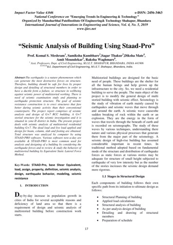
CE 243A Behavior & design of RC ElementsProf. J. W. WallaceOlive View Hospital Complex1971 San Fernando EarthquakeCE243A3Soft-story1971 San Fernando EarthquakeCE243AFall 0442
CE 243A Behavior & design of RC ElementsProf. J. W. Wallace1971 San Fernando EarthquakeCE243A51971 San Fernando EarthquakeCE243AFall 0463
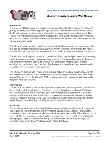
CE 243A Behavior & design of RC ElementsProf. J. W. WallaceConfinementTies @ 18” o.c.Spiral @ 3” o.c.1971 San Fernando EarthquakeCE243A7Cal State Northridge1994 Northridge EarthquakeCE243AFall 0484
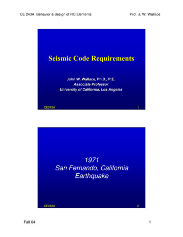
CE 243A Behavior & design of RC ElementsProf. J. W. WallaceCal State Northridge1994 Northridge EarthquakeCE243A9Northridge Fashion Mall1994 Northridge EarthquakeCE243AFall 04105
CE 243A Behavior & design of RC ElementsProf. J. W. WallaceBarrington Building1994 Northridge EarthquakeCE243A11Barrington BuildingHoliday Inn – Van Nuys1994 Northridge EarthquakeCE243AFall 04126
CE 243A Behavior & design of RC ElementsProf. J. W. Wallace1994 Northridge EarthquakezzMajor failures:– Steel moment-resisting frames– Precast concrete parking structures– Tiltup & masonry buildings with woodroofsMajor successes– retrofitted unreinforced masonrystructures– retrofitted bridge structuresCE243A131994 Northridge Earthquakez1997 UBC & NEHRPchanges:– removal of preprequalified steelconnection details– addition of nearnearfault factor to baseshear equation– prohibition onhighly irregularstructures in nearnearfault regionsCE243AFall 04– stricter detailing fornonnon-participatingelements– deformationcompatibilityrequirements– chords & collectorsdesigned for “real”forces– redundancy factoradded to designforces147
CE 243A Behavior & design of RC ElementsProf. J. W. WallaceSummaryzzzObservation of the behavior of real buildings inreal earthquakes have been the single largestinfluence on the development of our buildingcodesThe lull in earthquakes in populated areasbetween approximately 1940 and 1970 gave afalse since of security at a time when thepopulation of California was expanding rapidlyPerformance of newer buildings and bridges hasgenerally been good in recent earthquakes;however, older buildings pose a substantialhazard.CE243A15Seismic Codes and Source DocumentsSEAOCNEHRPASCE 7StandardBuilding CodeBOCA NationalBuilding CodeUniformBuilding CodeInternational Building CodeCE243AFall 04168
CE 243A Behavior & design of RC ElementsProf. J. W. WallaceIBC 2000, 2003zzzInternational CodeCouncil (ICC),established in 1994Seismic provisions– ASCE 77-02z Modelingz Forces– Material codesz ACI, ASCEIBC 2003 (ASCE 77-02,ACI 318318-02)CE243A17Material CodesInternational Building CodeMANUALOF STEELCONSTRUCTIONACI 318-02ACI 318R-02LOAD &RESISTANCEFACTORDESIGNBuilding Code Requirements forStructural Concrete (ACI 318-02)and Commentary (ACI 318R-02)An ACI StandardVolume IReported by ACI Committee 318Structural Members,Specifications,& CodesAISCaciamerican concrete instituteP.O. BOX 9094FARMINGTON HILLS, MI 48333Second EditionCE243AFall 04189
CE 243A Behavior & design of RC ElementsProf. J. W. WallaceShake Table Test – Flat PlateCE243A19Earthquake Building ResponseF4 m4a4(t)F3 m3a3(t)F2 m2a2(t)F1 m1a1(t)ShakingNote: Forces generallyIncrease with heightCE243AFall 04V(t) miai(t) i 1,4Time2010
CE 243A Behavior & design of RC ElementsProf. J. W. WallaceBuilding Response AnalysisIn general, three types of analyses aredone to design buildings subjected toearthquakesShakingz– Response History Analysisz Linear or nonlinear approach tocalculate time varying responses(P, M, V, δ)Sa– Response Spectrum Analysisz Linear approach to calculate modalresponses (peak values) andcombine modal responses– Equivalent Lateral Forcez Nonlinear approach used forrehabilitation (e.g., FEMA 356)z Linear approach – assumeresponse is dominated by firstmode response (very common)TimeSdF4F3F2F1VbaseCE243A21Building Response AnalysisResponse History Analysis– Analyze structure by applyingacceleration history at base ofstructure– Typically requires use of severalrecords– Elastic or inelastic response– Time consuming and results can varysubstantially between recordszResponse Spectrum AnalysisShakingzTimeSa– Elastic response– Determine peak responses for eachmode of response– Combine modal responses (SRSS,CQC)CE243AFall 04T2211
CE 243A Behavior & design of RC ElementsProf. J. W. WallaceAcceleration Response SpectrumMaximumAccelerationAgroundStructural Period, TT 2π MMKKShakingTimeCE243A23Displacement Response SpectrumMaximumDisplacementStructural Period, TT 2π MMKKShakingCE243AFall 04Time2412
CE 243A Behavior & design of RC ElementsProf. J. W. WallaceModal AnalysisSd,1Sd,2Sd,3T3Tn 2πφ nT Mφ nφ nT Kφ nT2T1δ max,n φ n S d ,nCE243A25Dynamic Building ResponseMDOF SystemStoryForcesSDOF Modelδx 4δx 4Sd,nSd,nδx 2δx 2δx 1δx 1Base ShearCE243AFall 042613
CE 243A Behavior & design of RC ElementsProf. J. W. WallaceADRS SpectrumzAlternative format forresponse spectrumSpectralAccelerationT constantz“Capacity Spectrum”approach – ATC 40zSpectrum for a givenearthquake versussmooth spectrumSpectral DisplacementCE243A27Code Analysis ProcedureszzUBCUBC-97 and IBCIBC-2000– Equivalent static analysis approach– Response spectrum approach– Response (Time) history approach– Other (Peer review)FEMA 273/356 & ATC 40– Linear Static & Dynamic Procedures (LSP, LDP)– Nonlinear Static Analysis (NSP) “pushover”– Nonlinear Dynamic Procedure (NDP)CE243AFall 042814
CE 243A Behavior & design of RC ElementsProf. J. W. Wallace1997 UBC Design Response SpectrumControl PeriodsTS CV/2.5CAT0 0.2TSV/W (Acceleration)2.5CACV/TLong-Period LimitsCAT0TSPeriod (Seconds)CE243A29UBC-97: Response Spectrum AnalysisCv IWRT2.5Ca IW R 0.11Ca IWVbase Eq. (30 - 4)VbaseEq. (30 - 5)VbaseEq. (30 - 6)Ca Seismic Coefficient (Acceleration)Cv Seismic Coefficient (Velocity)CE243AFall 043015
CE 243A Behavior & design of RC ElementsProf. J. W. WallaceModal AnalysiszzEigen Analysis– Requires mass (M) and stiffness (K) matricesz M is often assumed to be diagonalz K (e.g., from direct stiffness assembly)– Frequencies (ω(ω, T 2πT 2π/ω) and mode shapes (Φ(Φ)z Mode shapes φ are columns of Φ matrix(orthogonal property)Modal Analysis – solve uncoupled equations[ M ]{v } [C ]{v } [ K ]{v} { p}(t );{v} [Φ ]{ y}M n [Φ ] [ M ][Φ ] {φm } [ M ]{φn }m nTTM n y n Cn y n K n yn φ p (t )Tnsolve for ynCombine modal responses (e.g., SRSS, CQC)CE243A31UBC-97 Approach: Response SpectrumMDOF System ModelStoryForcesEquivalent SDOFδx 4δx 4Sd,nSd,nδx 2δx 2δx 1δx 1Base ShearCE243AFall 043216
CE 243A Behavior & design of RC ElementsProf. J. W. WallaceUBC-97 Approach: Response SpectrumPeak modal responses – 1st Mode{δ x 1, 4 }1 {φ11,φ21,φ31 ,φ41} S d ,1F1 M 1Sa ,1Tδx 2K1δx 1K1T1 Ct (hn )3 / 4Vbase,1 M 1Sa ,12Sd ,1 ω1 Sa ,1V/W (Acce leration)Acceleration,gF1 M1Sa,1δx 4δx 3Sd,1T1 2π M1T0 T1 TSPeriodPeriod(Seconds)(sec)Vbase,1CE243A33UBC-97 Approach: Response SpectrumPeak modal responses – 2nd to nth Mode{δ x 1, 4 }2 {φ12 ,φ22 ,φ32 ,φ42 } Sd , 2Tδx 4K2δx 3Sd,2δx 2δx 1Vbase,2CE243AFall 04Ti 2πMiKiF2 M 2 S a , 2Vbase, 2 M 2 S a , 2S d , 2 S a , 2 (T22 / 4π 2 )V/W (Acce leration)Acceleration,gF2 M2Sa,2T {T1 , T2 , T3 , T4 }T2 T0TSPeriodPeriod(Seconds)(sec)3417
CE 243A Behavior & design of RC ElementsProf. J. W. WallaceUBC-97 Approach: Response SpectrumModal CombinationszzPeak modal responses do not occur at the sametime, that is, the peak roof displacement for modeone occurs at t1 , whereas the peak displacementfor mode two occurs at t2, and so on. Therefore,peak modal responses must be combined basedon the correlation between modes.Modal Combination Approaches– SRSS: SquareSquare-rootroot-sumsum-squares, works wellfor systems with wellwell-separated modes (2Dmodels)– CQC: CompleteComplete-QuadraticQuadratic-Combination (3D)CE243A35UBC-97 Approach: Response SpectrumMass ParticipationzThe (force) participation of each mode can begauged by the mass participation factor.PFm,n zTypical mass participation factors: PFm– Frame buildings: 1st Mode – 80 to 85%– Shear wall buildings: 1st Mode – 60 to 70%– To achieve 100% mass participation, all modesmust be included in the modal analysisCE243AFall 04{φn }T [ M ]{r 1}{φn }T [ M ]{φn }3618
CE 243A Behavior & design of RC ElementsProf. J. W. WallaceUBC-97 Approach: Response SpectrumSpecific Requirementszzzzz1631.5.2 - For regular buildings, include sufficientmodes to capture 90% of participating mass. Ingeneral, this is relatively few modes1631.5.3 - Modal combinations – Use appropriatemethods (SRSS, CQC). For 3D models withclosely spaced modes – need CQC.1630.5.4 – R factors and limits on reducing baseshear where response spectrum analysis is used1630.5.5 – Directional effects: consider seismicforces in any horizontal direction (1630.1)1630.5.6 – Account for torsionCE243A37UBC-97 Approach: Response SpectrumDead & Live LoadszzzCombine responsespectrum analysis resultswith analysis results forgravity forcesLoad combinations (1612)– Same as new ACI loadcombinationsDrift limits (1630.10)– hs Story height– s Displ.Displ. for codelevel forces m 0.7 R sT 0.7 sec : m 0.025hsT 0.7 sec : m 0.025hsCE243AFall 043819
CE 243A Behavior & design of RC ElementsProf. J. W. Wallace1997 UBC – Equivalent StaticControl PeriodsTS CV/2.5CAT0 0.2TSV/W (Acceleration)2.5CACV/TLong-Period LimitsCAT0T1TSPeriod (Seconds)CE243A39UBC-97 Base Shear EquationsEquivalent Static AnalysisCv IWRT2.5Ca IW R 0.11Ca IWVbase Eq. (30 - 4)VbaseEq. (30 - 5)VbaseEq. (30 - 6)Ca Seismic Coefficient (Acceleration)Cv Seismic Coefficient (Velocity)CE243AFall 044020
CE 243A Behavior & design of RC ElementsProf. J. W. WallaceUBC-97 Approach: Equivalent StaticCv 0.40 N vFor Z 0.4, SB (Table 16 - R)Ca 0.40 N aFor Z 0.4, SB (Table 16 - Q)Z Seismic Zone Factor (0.075 to 0.4)S Soil Profile TypeNv Near Source Coefficient (velocity)Seismic Source A (M 7.0, SR 5 mm/yr)Distance 5 km Î Nv 1.6 (Table 16-T)Na Near Source Coefficient (acceleration)Seismic Source A (M 7.0, SR 5 mm/yr)Distance 5 km Î Na 1.2 (Table 16-S)CE243A41UBC-97 Equivalent Static AnalysisVbase I W R T Cv IWRTEq. (30 - 4)Importance Factor (1.0 to 1.25; Table 16-K)Building Seismic Dead LoadForce Reduction Coefficient (Table 16-N)Fundamental Structural PeriodT Ct (hn ) 3 / 4 0.02(48 ft )3 / 4 0.37 secCt Coefficient (e.g., 0.02 for rc walls)hn Building height (feet)CE243AFall 044221
CE 243A Behavior & design of RC ElementsProf. J. W. WallaceEquivalent Static Lateral ForcesDead & Live LoadsFtF4Fx F3(Vbase Ft ) wx hxn wi hii 1F2Ft 0.07TV T 0.7 secFt 0.0F1T 0.7 secVbaseCE243A43Lateral Force Resisting SystemLFRSCE243AFall 04“Gravity” System4422
CE 243A Behavior & design of RC ElementsProf. J. W. WallaceDetails of abuilding inEmeryvilleCE243A45“Non-Participating” SystemzzAlso referred to as: “Gravity” SystemFlat plate floor systems (Gravity loads)– Efficient and economical– Easy to form, low story heights– Strong column – weak beam conceptCE243AFall 044623
CE 243A Behavior & design of RC ElementsProf. J. W. WallacePerimeter LFRS and Interior “GFRS”CE243A47UBC-97: LFRS DesignEquivalent Static or Response Spectrum12 ftLFRSModel12 ft100 ft12 ft12 ft50 ftFloor PlanElevation View LFRSNote: Neglecting torsionCE243AFall 044824
CE 243A Behavior & design of RC ElementsProf. J. W. WallaceUBC-97 Equivalent Static AnalysisVbase Cv I0.4(1.6)(1.0)W W3/ 4RTR (T Ct hn )W4 (100' x 50' )(100 psf) 500 kipsW3 (100' x 50' )(100 psf) 500 kipsW2 (100' x 50' )(100 psf) 500 kipsW1 (100' x 50' )(100 psf) 500 kipsW 500 kips (4 floors) 2000 kipsCE243A49UBC-97 Equivalent Static AnalysisVbase Cv I0.4(1.6)(1.0)W (W 2000 kips)3/ 4RTR (T Ct hn )R Force Reduction Coefficient (Table 16-N)Accounts for nonlinear response of building(Building strength, ductility, damping)R 1 is associated with elastic responseTypical Values:R 8.5 for a rc special moment frameR 5.5 for a rc wall buildingCE243AFall 045025
CE 243A Behavior & design of RC ElementsProf. J. W. WallaceUBC-97 Equivalent Static AnalysisCv I0.4(1.6)(1.0)W WRTR (0.63)0.641.731.73 gMW W RR (0.37)R2.5Ca I2.5(0.4)(1.2)1. 2 g MW W RRR 1.2(2000) / R 1 2400 kips (elastic)Vbase VbaseVbaseVbaseVbase 2400 /( R 5.5) 435 kips (design)R 1.0 requires inelastic responseStructure must be specially detailed tocontrol inelastic behaviorCE243A511997 UBC Seismic Criteria(Seismic Zone 4, Soil Type SB, Na Nv 1)1.5Response SpectrumDesign Spectrum (CN)Design Force - R/I 4.5Design Force - R/I 8.5V/W 51.752Period (Seconds)CE243AFall 045226
CE 243A Behavior & design of RC ElementsProf. J. W. WallaceConfinementTies @ 18” o.c.Spiral @ 3” o.c.1971 San Fernando EarthquakeCE243A53UBC-97 Equivalent Static AnalysisF4Fx F3F2F1(Vbase Ft ) wx hxn wi hii 1Ft 0.07TV T 0.7 secFt 0.0T 0.7 secBase Shear Vbase 435 kipsCE243AFall 045427
CE 243A Behavior & design of RC ElementsProf. J. W. WallaceUBC-97 Equivalent Static Analysisn wi hi (500 kips)(12' 24' 36' 48' )F4i 1 60,000 kip - ftF3F2F1Fx 4 (435 0)(500 k )(48' ) 0.4V 174 k60,000 ft kFx 3 (435 0)(500 k )(36' ) 0.3V 131k60,000 ft kFx 2 (435 0)(500 k )(24' ) 0.2V 87 k60,000 ft kFx 1 (435 0)(500 k )(12' ) 0.1V 43k60,000 ft k4 Fx 174 131 87 43 435 kipsBase ShearVbase 435 kipsx 1CE243A55UBC-97 Equivalent Static AnalysisDead & Live LoadszF4F3F2zF1zBase Shear ρEhCE243AFall 04Load CombinationsUBCUBC-97 - S16.12.2.1– U 1.2D 0.5L 1.0E– U 0.9D / /- 1.0E– Where: E ρEh EvEv 0.5CaID 0.24DU 0.9D / /- 1.0(ρ1.0(ρEh Ev)U (0.9 /(0.9 /-0.24)D / /- ρEhρ redundancy factor 1.0Conduct static analysise.g., use SAP20005628
CE 243A Behavior & design of RC ElementsProf. J. W. WallaceUBC-97 Equivalent Static AnalysisDead & Live LoadsF4zF3F2zF1VbasezLoad CombinationsUBCUBC-97 - S16.12.2.1– U 1.2D 0.5L 1.0E– U 0.9D / /- 1.0E– Where: E ρEh EvEv 0.5CaID 0.24DU 0.9D / /- 1.0(ρ1.0(ρEh Ev)U (0.9 /(0.9 /-0.24)D / /- ρEhρ redundancy factor 1.0Conduct static analysise.g., use SAP2000CE243A57UBC-97: Drift & Drift Limitszz1630.9 – Drift for all analysisis defined– Defines drift forMaximum InelasticResponse Displacement( M ) and for DesignSeismic Forces ( S ): M 0.7R S1630.10 – Drift limits defined– Drift 0.025 times storyheight if T 0.7 sec– Drift 0.02 times storyheight if T 0.7 secCE243AFall 04Code levelDesign forces:Story Displ.: s(e.g., R 8.5) s,x 4 s,x 3 s,x 2 s,x 1Elevation View5829
CE 243A Behavior & design of RC ElementsProf. J. W. WallaceUBC-97 Requirementszz1633 – Detailed systems design requirements1633.1 General:– Only the elements of the designated LFRSshall be used to resist design forces– Consider both seismic and gravity (D, L, S)– For some structures (irregular), must considerorthogonal effects: 100% of seismic forces inone direction, 30% in the perpendiculardirectionCE243A59UBC-97 Requirementszzzzz16333.2 Structural Framing Systems1633.2.1 General:– Defined by the types of vertical elements used1633.2.2 For structures with multiple systems,must use requirements for more restrictivesystem1633.2.3 Connections – if resisting seismicforces, then must be on drawings1633.2.4 Deformation compatibilityCE243AFall 046030
CE 243A Behavior & design of RC ElementsProf. J. W. WallaceLFRS and Deformation CompatibilityLFRS“Gravity” SystemCE243A61LFRS and Deformation CompatibilityCode levelDesign forces:(e.g., R 8.5) s,x 4Story Displ.: s s,x 4 s,x 3 s,x 2 s,x 1diaphragmElevation ViewCE243AFall 04Plan View: RoofRigid diaphragmFlexible diaphragm6231
CE 243A Behavior & design of RC ElementsProf. J. W. WallaceUBC-97 Requirementsz1633.2.4 – Deformation compatibility– Requires that nonnon-participating structuralelements be designed to ensure compatibilityof deformations with lateral force resistingsystem– NonNon-participating elements must be capable ofmaintaining support for gravity loads atdeformations expected due to seismic forces– Design of LFRS:zzModel LFRS and apply design seismic forcesNeglect lateral stiffness and strength of nonnonparticipating elementsCE243A63UBC-97 Requirementsz1633.2.4 – Deformationcompatibility– For LFRSz M 0.7R S forzCode levelDesign forces:(e.g., R 8.5)Story Displ.: s s,x 4 s,x 3lateral frame at eachstoryThat is, computestory displacementsfor design seismicforces applied to theLFRS, then multipleby them by 0.7R s,x 2 s,x 1Elevation ViewCE243AFall 046432
CE 243A Behavior & design of RC ElementsProf. J. W. WallaceUBC-97 Requirementsz1633.2.4 – Deformation compatibility– Non-participating framez Model the system (linear - element stiffness)– Shear and flexural stiffness limited to ½ grosssection values– Must consider flexibility of diaphragm andfoundationz Impose story displacements on the model of nonparticipating frame– The imposed displacements produce elementforces, consider these to be ultimate– check stability (support for gravity loads)– Detailing requirements: 21.11 in ACI 318-02CE243A65UBC-97 RequirementszOther items of interest– Collectors (1633.2.6)zMust provide collectors to transfer seismicforces originating in other portions of thestructure to the element providing theresistance to these forces– Diaphragms (1633.2.9)zzCE243AFall 04Deflection of diaphragm limited by thepermissible deflection of the attached elementsDesign forces specified in (33-1)6633
CE 243A Behavior & design of RC ElementsProf. J. W. WallaceReinforced Concrete: ACI 318-02Chapter 21 – Seismic ProvisionszzzzCE243AFall 04Provide transverse steel- Confinement, buckling- Maintain gravity loadsStrongStrong-column, weakweak-beam- Beam flexural yieldingCapacity design- Beam & column shear- Joint regionsPrescriptive requirements- Little flexibility- Quick, easy, and usuallyconservative6734
ASCE 7 NEHRP Standard Building Code Uniform Building Code BOCA National Building CodeBuilding Code Uniform International Building Code. CE 243A Behavior & design of RC Elements Prof. J. W. Wallace Fall 04 9 CE243A 17 IBC 2000, 2003 zInternational