Transcription
Session 2663Rapid Prototyping for Manufacturing Engineering Technology ProgramAndrzej Markowski, Harry PetersenAutomotive and Manufacturing Engineering TechnologyMinnesota State University, MankatoAbstractDevelopment, presentation and evaluation of a Rapid Prototyping class for ManufacturingEngineering Technology (MET) students at Minnesota State University, Mankato is presented.The two credit (400/500 level) class has been designed as an open-ended one-semester project inwhich students work in small groups following the typical stages of product development designing, prototyping and manufacturing - in one continuous project. Students are required toapply in practice what they have learned from other classes. CAD, Manufacturing, Automationand Management classes are prerequisites. In-class instruction is limited. Students will oftenindependently follow class guidelines but must meet the all milestones of the project. One goal isto train students to approach and solve problems on their own, with guidance from an instructoras needed.1. IntroductionPage 5.517.1Manufacturing Engineering and Engineering Technology Programs are challenged with a rapidlychanging industrial environment, emerging new technologies, and new methods of production.MET graduates are faced with a demanding work environment at the shop floor, in the designingoffice, and on a management level. To meet the mission of these programs, and the expectationsof graduates and industries, universities need to prepare “industry-ready” students as much as itis possible. This is not an easy task, because of the wide variety of different industries in whichgraduates may be employed. Recent surveys show [1] that knowledge of new processes andtechnologies, and the ability to work in teams, are the most often mentioned competency gaps ofengineering and engineering technology graduates. Some reasons are obvious. In traditionalclassroom teaching, industrial projects can be analyzed theoretically but simulated only to acertain extent, never fully reflecting the complexity of conditions existing in industry.Additionally, traditional classroom teaching focuses narrowly on subjects directly related to theclass currently being taken, and it is difficult to incorporate a wide range of knowledge andexperience from other courses, even the prerequisites. Particular difficulty is encountered in theformat of class assignments. Rather than following the conventional linear instruction, in theRapid Prototyping class it is desirable to simulate a more real-world working and learningenvironment where students must develop their own methods to meet class guidelines in themost effective way. To be successful they have to use many technical tools from different areas.In introducing this class, we had two major goals. The first was to prepare students to work inteams to solve open-end designing and manufacturing problems and to develop the necessaryskills for using modern computer integrated manufacturing in an industrial environment. Thesecond goal was to develop a course so closely linked to local industry that current projects couldbe picked by students directly from problems submitted by the cooperating companies.
Incorporating the Internet, and the latest developments in computer technology, provide greatopportunities to improve the students’ preparation for industry. Well established “live links,”plus cooperation between the university and participating industrial companies, will bring currentproblems directly to the university labs. This synergy will provide dividends for all: a fresh lookat problems and methods of solving the open-ended problems similar to those encountered inindustrial settings for students, and industrial and student access to the advice and expertise offaculty for participating industries.Nationally, the need for this type of arrangement is generally understood by everyone involved,and there is an increasing realization that return on investment in training and development canbe significant [2]. Educational initiatives sometimes have a very large scale. Six large, diversemanufacturers and three state universities are working together cooperatively to define industryeducation needs and jointly design new experience modules [3].A large employer has developed an education program which teaches the concept of short-cyclemanufacturing and how to improve their operation. It helped the company to achieve significantimprovements in reducing work-in-progress inventory, cycle times, and costs [4]. However, themain role in these initiatives belongs to educational institutions, especially the engineeringdepartments of universities. The general trend is to move away from traditional one-subject, inclass instruction to interdisciplinary hands-on engineering programs, which pool resources withother academic institutions, and partner with industry or government institutions [5]. Someuniversities have developed courses, which involve mechanical, industrial, electrical, andmaterial engineering students. Accounting, marketing, and information students are integratedinto some teams as well. [6,7].2. Why Teach a Rapid Prototyping Class in a Manufacturing Program?Rapid prototyping by definition is a technology used for generating physical parts (prototypes)directly from technical documentation, usually in an early stage of new product design. Inpractice, however, it is much more. Effective use of rapid prototyping requires a higher-level useof computers, computer-aided design and engineering, and on-line communication across anenterprise. [8] Rapid prototyping also requires developing systematic cooperation among variousspecialists ranging from art and engineering designers, and marketing specialists, to those peopledirectly involved in production preparation and manufacturing. Product development starts whenmarket research indicates that there is need for a new product or for improving an existing one.Product information can come from such different sources as the market research group, toproduct users in the form of a manual sketch, photo image, technical drawing, computer file or aphysical object. These data must first be transferred into precise technical documentation, theninto a series of prototypes. Rapid prototyping allows engineers to create both physical modelsand full technical documentation of a product in a matter of days rather than weeks or months.These prototypes are used by engineers to verify the form, fit and function of the design. Thisenables them to detect problems earlier in the design process, and to bring products to marketfaster and with a lower design cost. Costs of designing and developing a new product oftenrepresent a significant part of the total cost of the product. Rapid prototyping can reduce thiscomponent of overall cost as well as reduce significantly the time-to-market factor. [9]From an engineering and engineering technology educational viewpoint, the rapid prototypingprojects will allow students to use their own creativity to arrive at a unique solution to a problem.Page 5.517.2
3. Rapid Prototyping Class ProjectThe RP class project for engineering technology seniors is as an open-ended project whichenhances the Manufacturing Engineering Technology students’ preparation while teaching themto invent their own problem solutions. Students must have successfully completed theprerequisite courses (Computer Aided Design, Manufacturing and Manufacturing Automation,Strength of Materials and Industrial Design) to be admitted to the RP class. Students work insmall groups (typically three members per group) on all stages of the project.Project DescriptionA description, intentionally general, of a sample RP project which was given to the studentsfollows. The emphasis is on “things to do” to create an efficient problem-solving method ratherthan on the specifics of the problem.Students were told to design a mechanism which is a part of packaging machinery. Themechanism has to provide a 90 degree indexing of the output shaft when the input shaft makesone full revolution. The indexed shaft should stay locked until the next impulse from the inputshaft comes. Frequency of indexing is at least 60 times per minute, and expected torque on theoutput is 2.5 inch-pounds. Space is not limited and the input shaft is parallel to the output shaft.One hundred mechanisms will be needed to support one year of production.Suggested problem approach- Analyze the situation and come up with more than one possible technical solution. Choose oneand justify why it is the best.- For the selected design, produce complete technical documentation going from the handsketches to the fully dimensioned CAD files.- Perform the computerized stress-strain analysis of the crucial elements of the design to checkthe mechanical stress and deformation under normal working conditions, and when themechanism is suddenly overloaded.- Correct the documentation files if any changes are necessary.- Make physical, fully functioning prototypes to verify form, fit, and function.- Analyze the prototype for design and functional flaws.- Make corrections in the basic documentation if any changes are necessary.- Prepare a set of product documentation including marketing illustrations, catalog data andstandard technical documentation.- Prepare production documentation for the product, including CNC programming, selection oftools, fixture or pallet design, material selection and treatment, and methods of inspection.- Prepare the final model and report to turn in, and give a public presentation.Project AssumptionsPage 5.517.3- Designing, prototyping and manufacturing facilities are at different locations and a system ofcommunication has to be used to set up the working links between these locations.- Work-in-progress should be accessible by all the participating team members. A proper filemanagement system has to be developed and used.
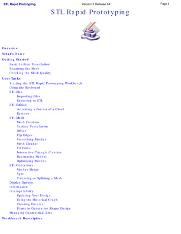
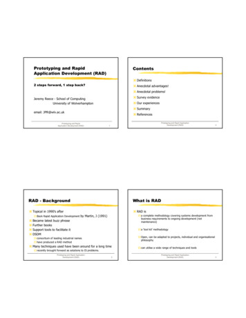
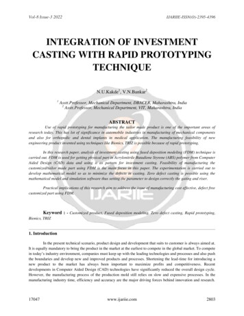
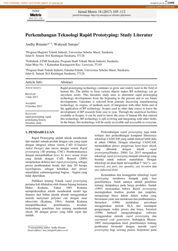
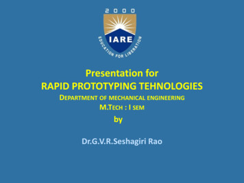
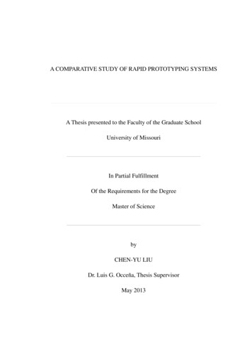
- Project evaluation is based on quality and completion of listed “things to do”. Students’statements are required to say what was the involvement of each member of the group.- Each project should begin with work scheduling; Microsoft Project software is recommendedto accomplish this. Meetings with faculty are scheduled bi-weekly (or by appointment) toanalyze work-in-progress.A brief orientation introduces students to the equipment, manuals, on-line help, and technicalsupport available from technicians to run the CNC equipment and informs them that laboratoryfacilities are available to students outside scheduled class times. (Fig.1).At the beginning of the semester all students have assigned accounts at the local server. “Contactboxes” are created for the teams to make the work available for all group members. Studentshave to demonstrate proficiency in the use of e-mail, ftp, and web viewers for communicationbefore working on projects. A training session is provided by the network manager.Sample Project DetailsAfter an open discussion session, the Geneva Mechanism was selected from two otherpossibilities. Criteria used for evaluation were fewer moving parts, and the possibility to confinethe mechanism to protect it from dust and to reduce noise. First sketches confirmed that themechanism met the basic requirements of the project. The team started the project with a handsketch to show the idea of the mechanism and its location in the machinery. (Fig.2). An Internetsearch of results for similar objects was required for this part of the project.Documentation - project documentation required use of a CAD package. Students usedAutoCAD because they knew the system from prerequisite CAD classes. R2000 and MechanicalDesktop programs were available to them. The required documentation format was an assemblydrawing as a solid model, and a detailed 3-D drawing file as the necessary technicaldocumentation for prototyping, manufacturing, inspection, and production preparation. (Fig.3).All documents were stored on the local NT Server so all participants could access and reviewthem. AutoDesk!Whip software was used to view the drawings on the web. Optionally, drawingscould be viewed using Unix Show Me software on Sun workstations in the lab [Fig.4].Page 5.517.4Stress-strain analysis – a parallel path to prototyping was computer simulation of the load-stressdeformation of the object. This option is used only when the objects are subjected to the loads,which in return can affect functions or performance if loads are excessive. Due to the limitedexposure to mathematics required for engineering technology students, we chose to adopt theDesign Space package from ANSYS [10] rather than the full Finite Element Analysis approach.This Finite Element Analysis based package is designed for analysis of stress and thermaldeformation, and vibration of mechanical elements. It was used only during the design process.The Design Space system provides immediate solutions to the questions relating to the type andshape of deformations and stresses of the elements under working conditions. Students workingon prototypes can easily evaluate the weak points in the design and redesign some elements toprevent excessive deformations and stresses for normal and overload conditions. For the GenevaMechanism, the Design Space package was used along with the Mechanical Desktop to providethe stress-deformation analysis of some parts of the mechanism [Fig.5]. The results of the stressstrain analysis were available before the physical objects were made. Manufacturing students can
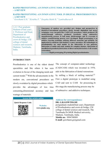
easily learn the software, and usually one class period demonstration of software results in abasic working knowledge, although interpretation of the results of calculations will take longer.The Design Space report was the subject of an open discussion to discover the weak and strongpoints of the design. [Fig.6]. Documentation changes necessary were made at this time, and thedocumentation files were prepared for prototyping.Prototyping - the next step was prototyping, or making physical models. Students used twomethods: additive and subtractive. Using additive method plastic objects were built on the ActuaThermoJet Solid Object printer [11]. This machine builds precision objects layer by layer. Onedisadvantage, however is that objects produced have a very low strength, which makes assemblyand running of the whole mechanism difficult. This method is useful for shape and fit evaluation,however. [Fig.7]. Using subtractive method students also milled the model on a Rolandprototyping mill, which is a scaled down CNC milling machine. This method required morepreparation operations, but the objects can be made out of much more durable material. Thestronger parts could be assembled and mechanism operated. [Fig.8] There were two importantissues in this stage of the project. The first was the conversion of file formats from one CADsystem to another, and the second issue was to teach students how to use, the file managementsystem. Problems with CAD file conversion from one format to another have not yet beencompletely solved in industry and students could see some conversion limitations.Manufacturing students in the RP class knew two CAD/CAM systems, AutoCAD (MechanicalDesktop) and MasterCAM, from other classes. A third file format, stereolithography (STL files),was created for use by the Actua ThermoJet printer. When conversions were done, the newformats were inspected for possible errors before proceeding with prototyping. This stage of theproject was left to the students. They were free to search the Internet, system help files, or evencontact support technicians. The goal was to develop some “self-help” skills, specificallyimportant when the software environment is changing very fast. The file management systemwas used to transfer files at different stages of the project. A Windows NT server was used aswell as resources, communication and storage from any location on campus or from outsideanalysis of the model-elements and assembly. Analysis at this stage of the project concentratedon two elements: design flaws: fitting parts together, and possibilities of design improvements byreducing the weight and material selection, as well as developing a concept of manufacturing andadapting the design to the process requirements. Three basic manufacturing processes wereconsidered for this project: injection molding, casting or CNC machining. The following aspectswere considered: manufacturing equipment available, overall costs, product durability, andnumber of products required per year. For the sample project, CNC machining was selected,which best met the considerations listed above. Design materials analysis resulted in selection ofhigh density polymer for the housing of the mechanism, and hard aluminum for the remainingparts of the mechanism.Production preparation - this stage of the project required development of the CNC programs anddesign of adequate tooling for milling and turning operations [Fig.9].The plan of operationincluded specification of tools and materials, and material preparation. The requireddocumentation format included the electronic data file, and a hardcopy print of the filescontaining the CNC machining code ready to download to the CNC controller.Page 5.517.5
Part Production and InspectionThe CNC equipment was run (under supervision of faculty or technician) to produce some parts.[ Fig.10]. These were assembled and operated. Following mechanism operation shop floorinspection station a CMM was used to evaluate the parts.Post-class evaluationAll students completed their prototypes, which were assembled and operated. Following thecourse, a focus session with students revealed great enthusiasm for the course. Every studentsuggested new uses for rapid prototyping. Most stated that this should be a required course, withmore time and projects. Other comments included: an enhanced understanding of Internetpotentials, better appreciation of lead-time reduction, a good cap-stone course for manufacturing,and a desire to learn more. Students related the value of rapid prototyping to many areasincluding communication, ergonomics, and concurrent engineering. While the students weregenerally very pleased with the course, there was a consensus that a more comprehensive guidebook would be valuable, and that more time (and credit) would be worthwhile. The IndustrialAdvisory Board for the College of Science and Engineering strongly endorsed the subject ofrapid prototyping.5. ConclusionsWe found this rapid prototyping class to be a powerful and attractive method of teachingadvanced manufacturing. However, the class requires extensive preparation time from facultyand staff, and strong departmental support. Equipment, computer networks, and software mustbe purchased, prepared and made accessible for students. Our main goal is to let students workin small teams, optimize their time, enjoy the work, and provide their solution to the problems;this can be achieved when the right teacher-student links are set up, and students know theevaluation criteria at the beginning of the class so they can prepare their work accordingly. TheRP class still has much room for improvement. The following are some ideas being consideredfor introduction in next editions of the class:- Increase class time to 3 credits;- Write an operational guidebook;- Introduce parametric CAD system for some projects which will make it possible to createmuch more advanced CAD documentation;- Use more current problems from local industry, get students more involved, and possiblycontinue some projects as internships;- Introduce elements of cooperation and competition between the teams.Page 5.517.6
Bibliography1. “Manufacturing Education Plan: 1999 Critical Competency Gaps” by the Society of Manufacturing Engineers,Dearborn, MI 1999.2. Schriver, Rob; Giles, Steve; Curtis, Gary, “Establish performance measures to calculate business results andreturn on investment in training and development.” Proceedings of the American Power Conference[Proc Am Power Conf] 1999.3. Elliott, Charles S; Sevier, John, “Really getting industry to partner in manufacturing education.” TechnicalPap Soc Manuf Eng, SME Dearborn 19964. Deaton, Ron; Kraebber, Henry W, “Bringing the concepts of modern manufacturing into the work place.”Technical Pap Soc Manuf Eng, SME Dearborn, 19965. Valenti, Michael, “Teaching tomorrow's engineers.” Mechanical Engineering, vol.118, no. 7. 19966. Brown, Max L; Thompson, David; Seidman, Gelizabeth, “Manufacturing engineering education usingindustrial projects and combined multidisciplinary teams from several universities.” Technical Pap SocManuf. Eng, SME Dearborn,7. Bakr, MM, “Manufacturing as a catalyst for integration with other disciplines. 1996, 5pp, Technical Pap SocManuf. Eng, SME Dearborn8. Petersen, H., “Introduction to Rapid Prototyping” manufacturing” Manufacturing Conference, Mankato,1997.9. Petersen, H.; Markowski, A. “File transfer in rapid prototyping” CIM ASME Conference, Irvine, California,1997.10. Design Space User Manual for Release 5 by ANSYS. Inc. 199911. Actua ThermoJet Solid Object printer. User Manual by 3D systems, 1998ANDRZEJ A. MARKOWSKIAndrzej A. Markowski is a Professor of Automotive and Manufacturing Engineering Technology Department ofMinnesota State University, Mankato Minnesota.HARRY C. PETERSENHarry C. Petersen is an Associate Professor of Automotive and Manufacturing Engineering Technology Departmentof Minnesota State University, Mankato Minnesota.Page 5.517.7
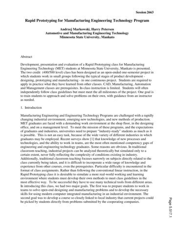
Management level: searching the market, orders, project orkstWindows NT WorkstationsSoftware for project:AutoCAD 14/2000Mechanical DesktopDesign SpaceProduct:Solid modelsStress-Strain ReportDetailed DocumentationPrototypeMillPototyping Machines:3D PrinterRoland MillSoftware:MasterCAMProduct:Plastic Models: elementsand assemblyManufacturingCNCMillCNCLatheEquipment:CNC Machining CenterCNC Turning MachineSoftware:MasterCAMProduct:Durable PrototypesShort SeriesMolds for InjectionOn-line communication: e-mail, FTP, web viewing, confeencingNT L o c a l S e r verFig.1. Rapid Prototyping Lab ConfigurationFig. 2. A “Concept” Sketch of the MechanismPage 5.517.8
Fig.3. Solid Model of the Mechanism (Mechanical Desktop)Page 5.517.9Fig. 4. Viewing an Assembly Drawing on the Web
Fig. 5. Deformation Analysis Results (Design Space)Fig. 6. Design Space Web Format Report Containing Results of Stress and DeformationAnalysisPage 5.517.10
Fig. 7. Plastic Prototype of Geneva Mechanism made on the ActuaThermoJet Printer.Page 5.517.11Fig. 8. Machining Case out of Plastic on the Roland Prototyping Mill
Fig. 9. Tool Path Generation (MasterCAM System)Page 5.517.12Fig. 10. Final Milling of the Case on Machining Center
Page 5.517.13
Rapid prototyping by definition is a technology used for generating physical parts (prototypes) directly from technical documentation, usually in an early stage of new product design. In practice, however, it is much more. Effective use of rapid prototyping requires a higher-level use