Transcription
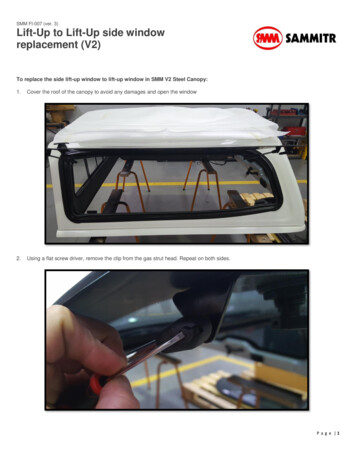
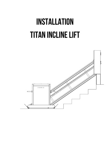
INSTALLATIONTitan Incline Lift
2Note to the reader :1.This document is for elevator technicians alreadytrained on this kind of equipment.2.Technical training must be attempted at AmeriGlidebefore servicing any of their equipment.3.Every components shall be provided by the liftmanufacturer4.Make sure to have all required parts and tools.
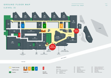
3MAIN COMPONENTS1)2)3)4)5)6)7)8)9)10)PLATFORMHAND RAILVEHICULE COMMANDSSAFETY ARMSAFETY FLAPUNDER PANGUIDE RAILSEMERGENCY MOVING DEVICECUT-OFFTOP LANDING CALL STATION
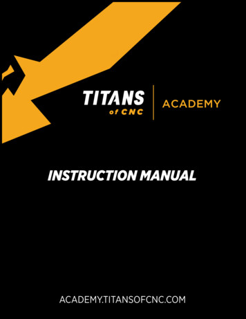
5COLUMN INSTALLATIONa)b)c)d)Remove column front facia by removing perimeter.Remove the motor gearbox assembly.Locate column lower corner with the last step bullnose.Use no.12 wood screw for column anchoring.
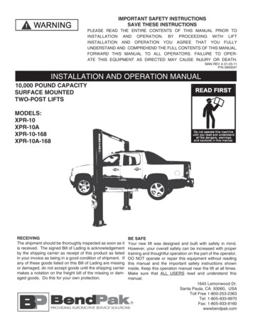
6GUIDE RAILS INSTALLATION(SELF SUPPORTING)If the adjacent wall is not strong enough to support the reactions stated in theinstallation drawing, it is feasible to install self supporting legs on each step.These legs shall be evenly distributed, the same way as the stud would belocated in a standard wall. The maximum spand between 2 legs is 16’’.a)b)c)d)Locate the legs on each step, plumb.Use all mounting holesUse only specified anchors on the installation drawingUse ¼-20 UNC screw for rail mounting on the legs.Anchors legs example
7GUIDE RAIL INSTALLATION(STUD WALL)Guide rail will be shipped already assembled with spacers or screwed onplywood. The installer needs to join he column to the rail itself using the metalbracket ‘’ RACCORD’’ already installed on the column.a)b)c)d)e)f)g)Place the rail assembly on the wallScrew the rail ‘’Raccord’’ to the upper rail endLocate anchoring structure in the supporting wallScrew each Rail into each anchoring structureUse only no.12 wood screw for wooden stud wall.Use only ¼-20 UNC for steel structure.Reinstall metal coversAnchoring Structure Example
8PLATFORM INSTALLATIONa) Install platform on rail by inserting Charriot #2 in the rail. Make sure toleave about 1/8’’ gap between chariot #4 wheel bolts heads and the insideface of the rail.b) Slide in chariot #1 between back of platform and supporting wallc) Slide the bolts in the arc shaped slotsd) Make sure all wheels are running on the rail surface, otherwise adjustchariot accordingly. Tight in place and add cotter pins on each bolt.e) Attach the lifting chain to the safety brake using the #50 quick linkprovided with the chain.f) Install the upper mechanical stop.g) Remove the brake lock screw. ( Front panel will not fit otherwise )h) Make all electrical connections as per schemes BEC03 9X9 au BEC04Z3
9UPPER MECHANICAL STOP
10SAFETY ARMSARM JOINTFLAP CABLEa)b)c)d)e)f)Install lower arm by using the provided bolts un the platform structureInstall the (gas spring or linear actuator)** on the lower arm leverJoin the lower and upper arm in the arm jointInstall the upper arm the same way the lower arm was installedInstall the (gas spring or linear actuator)** on the upper arm leverInstall the flaps cables on both arms and adjust so those flats are morethan 45 with the horizontal in the uppermost position.g) Adjust the arm switch in such way that electrical circuit is opened whenone of the arms is more than 15 with the horizontal.**NOTE:MANUAL ACTION VEHICULE REQUIRE GAS SPRINGAUTOMATIC ACTION REQUIRE LINEAR ACTUATOR
11FLOORa) Install the (gas spring or linear actuator)** on the floor rockerb) Adjust the floor level with ½ nominal weight (250 LBS)c) Adjust all floor level switches so that a 15 will open the circuit**NOTE:MANUAL ACTION VEHICULE REQUIRE GAS SPRINGAUTOMATIC ACTION REQUIRE LINEAR ACTUATORFINALIZINGa)b)c)d)Install the lower call stationRout the electrical power to the cut offInstall screw covers on railsInstall front platform cover
12INSPECTIONTitan
13BEFORE SERVICINGa) Run a safety brake functional testb) Check the alarm and E-stop while travelingc) Check the emergency lighting by cutting the main breaker off, not the cutoff.d) Check the underpan safety by lowering the platform and activate thecircuit.e) Make sure Flaps are working fine, and that the platform will not move ifflaps are down.f) Double check all structure bolts torquesg) Run a safety test in case of failureh) Run a couple of complete travels of the elevator.SAFETY BRAKE TESTa) Jam the lowering of the vehicule with the means of a 2X4 stud about 1Mlongb) Lower the platform frame against the stud in order to create a chain loosec) Stay away from the platform trajectory and wipe out the stud with themeans of a rope.d) Platform must stop in less than 60mm measured along the travel line.e) Chain must be still loose, meaning the brake really stopped the car.f) All command must be inhibitedg) Use the manual moving device to lift the platform and release the safetybrake.h) Rearm the safety brake and the manual reset safety switchi) Reset the controller
14MANUAL MOVING OF THE PLATFORM
15BATTERY CHARGER TEST PROCEDUREa) Unplug the charger unit from the 120Vac socketb) Run 5 complete travel in order to partially discharge the battery bankc) Make sure the electrical connections are connected such as the redterminal is on the positive electrode and the black on the negativeterminal.d) Using an ampmeter, measure the charging current on the red wire.e) If current is over 1/2A, chargers are finef) Once the battery are charged, the pilot light must remain off
16TEST PROCEDURE IN CASE OF FAILUREThis procedure explains how to test the protection in case of failure. Thisprocedure must be followed only by certified technicinans.DANGER: THIS TEST PROCEDURE WILL EVERYPERSONSSURROUNDING THE PLATFORM.
17MAIN CONTACTOR C1a) Install a min 18AWG jumper between terminal 60 and 68. This willapply 24Vdc directly on the C1 coilb) After 1.5 sec, the controller will code a fault. The indicator for output Awill become negative image.c) Remove the jumper between terminal 60 and 68d) Reset the controller by pressing the Z4 buttone) Connect one end of a jumper to the terminal 60f) Call for an upper landing, connect the other end of the jumper to theterminal 68 and press the E-Stop.g) Lift should stall immediatelyh) Remove jumper between terminal 60 and 68i) Reset the controller by pressing the Z4 buttonj) Disconnect the wire from terminal 65k) Call for an upper, or lower landingl) Lift should stall about ½ second after the beginning of the movementm) Reconnect wire to terminal 65n) Reset the controller by pressing the Z4 button
18UP CONTACTOR ( M1 )a) Install a min 18AWG jumper between terminal 60 and 67. This willapply 24Vdc directly on the M1 coilb) Call for an upper landing, after 1.5 sec, the controller should code à faultc) Reset the controller by pressing Z4 on the PLCd) Call for an upper landing and press the CAB E-stop, Lift should stallimmediately.e) Reset the controller by pressing Z4 on the PLCf) Call for an upper landing and activate the upper safety flap the same wayit would hit an obstacle by moving upward.g) Lift should stall and code à faulth) Remove jumper between terminals 60 and 67.i) Reset controller by pressing Z4 on the PLCj) Remove wire from terminal 64k) Call for an upward move , lift should stall after 0.5 sec, and code a faultl) Reset controller by pressing Z4 on the PLCm) Reconnect wire to terminal 64n) Reset controller by pressing Z4 on the PLC
19DOWN CONTACTOR (M2)a) Install a min 18AWG jumper between terminal 60 and 66. This willapply 24Vdc directly on the M2 coilb) Call for an lower landing, after 1.5 sec, the controller should code à faultc) Reset the controller by pressing Z4 on the PLCd) Call for a lower landing and press the CAB E-stop, Lift should stallimmediately.e) Reset the controller by pressing Z4 on the PLCf) Call for a lower landing and activate the upper safety flap the same way itwould hit an obstacle by moving downward.g) Lift should stall and code à faulth) Remove jumper between terminals 60 and 66.i) Reset controller by pressing Z4 on the PLCj) Remove wire from terminal 63k) Call for an downward move , lift should stall after 0.5 sec, and code afaultl) Reset controller by pressing Z4 on the PLCm) Reconnect wire to terminal 63n) Reset controller by pressing Z4 on the PLC
20GROUNDINGThis test will prove that over current protection devices are working fine andwill protect the electrical equipment in case of short circuit.Connect thenegative terminal from an ohmmeter to the negative terminal of the batterybank. Measure electrical resistivity between battery negative terminal and: Electrical enclosure mounting plate Ternimanl 61 into each contrôller Metallic points around each switch Metallic points around call station Ruide Rails Platform frame Underpan Flap ColumnEach meausre must be under 0.3Ω
21MAINTENANCETitan Incline
22BIANNUAL MAINTENANCECAB Commands buttons are in good shape Adjust level switches Check ultimate limits switch Check emergency lighting Check floor mouvement and limit switches ( Cut over 15 Deg ) Check safety arms movement and limits switches ( Cut over 15 Deg ) Check safety flaps movements and limits switches ( Cut under 45 Deg ) Check if phone is working proprely Make a safety brake test Test E-Stop in motion, lift should stall immediately and chime should beheard.UNDER PAN No foregin debris is located inside the underpan Underpan is free of movement in any direction Check and test all safety switches
23BOGGY Check the chain connecting link on safety brake Check tightening torque on guide wheels 3/8-16 NC at 23 lbft Check for undesirable noise and/vibration Vérifier le bon état de la maille de raccord de la chaîne Serrage des boulons de roues 3/8-16 NC à 23 LBxPICOLLONETTE Inspect lifting chain Inspect chain drive pignon Inspect chain guide and change if any wear can be seen Inspect controller general condition, cleanness, no modification Cleanness of power contactor contacts Battery terminal ( No corrosion ) Battery Bank ( No Leak ) Battery are not swollen Check call station functionality Make a cab command priority test Remove any foreign debris in the chain compartment Make a test of protection in case of failure Test the manual lowering device
24USER MANUALTitan Incline Lift
25WARNING This is not a dumbwaiter This is not an amusement ride This is not a rollercoaster This unit is dedicated to me used only by peoples in a wheelchair Never overload this lift Do not use in case of emergency Do not use in case of flooding This unit is not dedicated to be used in a humid place Kid should not use this lift unless it is a pediatric dedicated unit Never go under the lift Never modify the lift without the manufacturer approval Any modification on the stair shaft is prohibited after liftinstallation Never try to repair the lift by yourself A biannual maintenance is recommended for a safe use of thelift.
26RATING PLATE
27WarrantyThe Titan Incline Lift is warrantied for a period of one year aftercommissioning. This warranty covers parts and labor for anymanufacturing defect or failure under a normal use of the lift. Thisdoes not cover warranty of merchantability for a specific use or need.Customer and ergo therapist are responsible to ensure this unit suit theneeds of the limited mobility user. Also, Architect and buildingengineer are responsible to ensure this unit suit the building code andstructure strength. Always try disable lift before purchasing, anyorder is assumed to be in conformity with local building codes andwill be delivered as ordered. Dealers and installers are responsible tocollect all permits before starting the installation.
28Components1)2)3)4)5)6)7)8)9)10)PLATFORMHAND RAILVEHICLE COMMANDSSAFETY ARMSAFETY FLAPUNDER PANGUIDE RAILSEMERGENCY MOVING DEVICECUT-OFFTOP LANDIN CALL STATION
29MANUAL MOVING OF THE PLATFORM
30MAINTENANCE Do not attempt mechanical maintenance or modification Do not add or remove lubricant on any part of the installation Any defect should be reported to the installer Clean painted parts with the means of a soft soap and cloth It is allowed to use automotive wax and shine on painted surface The best maintenance you can do is to keep your lift clean Clean rails as often as possible in order to prevent dustaccumulation on guide wheels.USE Call the lift by using the call station Unfold the floor Roll on the lift with your wheelchair facing front Put your parking brake on your wheelchair Unfold safety arms Use the commands to reach the other landing Hold untill the vehicule has reached the other landing Open the safety arm Leave the lift Flold the floor back to the wall to free the staircase
31FLOOR UNFOLD(Electrical)The Titan Incline Lift is available with an electric action of thefloor and safety arm. Usually the floor and arm must be unfoldedmanually, butin some case it is too difficult for the user depending on its disability.The electrical option is using the same commands for all operations.Any commands asking for a move beyond the travels limits willactivate the floor and arm. A command to the other landing of a folded lift will unfold thelift for boarding. A command to the current landing will fold the floor and armalong the supporting wall.
32SAFETY EDGESThe Titan Incline Lift is equipped with safety edges sensors. In theevent of a contact with any object along the travel, the lift shouldstall this motion and allow for a backward movement of the lift. Thismean the user will be able to free the obstruction. The first thing todo in the event of an irresponsive lift is to check all safety edges,and free any obstruction.
b)Call for an lower landing, after 1.5 sec, the controller should code à fault c) Reset the controller by pressing Z4 on the PLC d)Call for a lower landing and press the CAB E-stop, Lift should stall immediately. e) Reset the controller by pressing Z4 on the PLC f) Call for a lower l