Transcription
Palletizer Functional Safetywith relay and configurablerelay solution.RRRR
IndexOverview3Working principle3Example of palletizer and depalletizer equipment4&5Risk assessment requirements6Significant hazards7General hazards8Guarding requirements9Safety relay with selectable configuration10Safety relay with software configuration12Safety Light Curtain operation15E-Stops19Gate switches20Personnel access functional description22Connection details for solenoid release key24List of materials26Annex: Function blocks282Palletizer Functional Safety with relay and configurable relay solution.
OverviewThis document has been developed for machinedesigners within manufacturing plants and also toassist system integrators and OEM's.The specification covers the implementation frominput devices through to final power elementsgiving examples utilizing a safety relay basedsolution and a configurable controller solution.The diagrams in this document should be used inconjunction with the additionalrecommendations detailed in:EN 60204-1: Safety of Machinery – ElectricalEquipment of MachinesA detailed description of those standards is providedin Safebook 4, available from Rockwell nloads/safebook4 FormFor muting Rockwell Automation provides detaileddescription of the complete safety erviewDownload Safety Automation /safety/en/Safety Automation BuilderANSI B155.1 - Safety requirements for packagingmachinery (North America ).EN 415-4: Safety of packaging machines Palletizers and Depalletizers (Europe).Note: Different regions may have different guidelines.When implemented correctly the circuits describedin this whitepaper will comply with the requirementsfor PLe (Performance Level) to (EN) ISO 138491: 2015 and SIL3 (Safety Integrity Level) to IEC62061: 2005.Working PrinciplePalletizer – Layers of packages are formed at onelevel usually a high level, and transferred ontothe pallet which is raised and then lowered asthe pallet forms.A depalletizer operates in reverse: layers of packagesare gripped and moved from a pallet onto a receivingtable, usually positioned at high level. The height ofthe pallet is raised as the pallet is dismantled.3
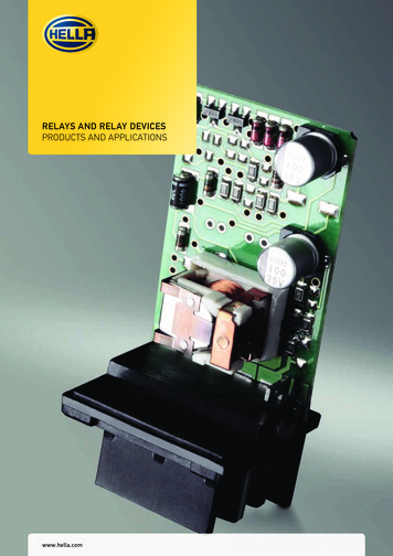
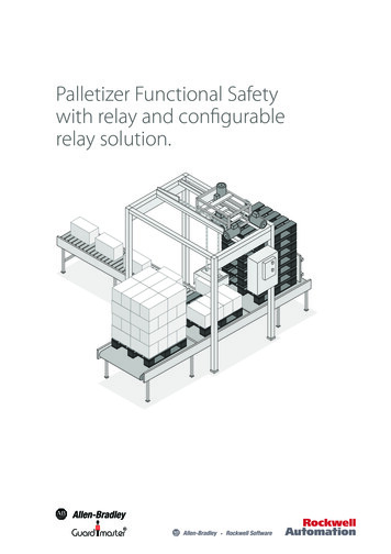
Example of palletizer anddepalletizer equipmentSignificant Hazard cross reference listThe palletizer usually comprises the following equipment:1Load lifting device4Mass of pallet in the stack7Interlayer placing unit2Pallet conveyor5Collating area8Product in-feed conveyor3Mass of product on the pallet6Mass of product9Electrical cabinet75469Side view3218Plan view4Palletizer Functional Safety with relay and configurable relay solution.
Product cross referenceSensaGuard safety switchSee page 20 forfurther detailsSafety contactorSee page 24 forfurther detailsSafety lightcurtain'L' Type Photoelectric sensorTrapped Keygate switchSee page 15 forfurther detailsSee pages 15 & 16 formuting requirementsSee page 22 forfurther details440C-CR30ConfigurableSafety relaySee page 12 forfurther details5
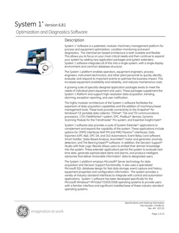
Risk Assessment RequirementsBased on the figure below, application of anapplicable type-C standard may be applied, in thisinstance EN 415-4 as the machine is being producedfor a market within Europe and as such references aEuropean standard. However it should be noted thatthere is still a requirement to review the standardto ensure that all significant hazards are dealt with.Regardless of where the machine is to be installed,the information contained within ISO 12100-1 shouldbe valuable.STARTYESMachinecompletely coveredwithin the scope?Applicable type-Cstandards exists?NONOYESAll significanthazards dealt withand associated risksappropriatelyreduced?NOYESApply type-C standardApply type-C standard & ISO 12100 inconjunction with appropriate type-Bstandards for the hazards not dealt withand/or where risks are not appropriatelyreduced by the type-C standardsApply ISO 12100 inconjunction withappropriatetype-B standardsRecommended steps for the practical use of ISO 12100: 2010 and existing type-B and type-C standardswithin this system. See Safebook 4 from Rockwell er Functional Safety with relay and configurable relay solution.
Significant HazardsThe following table lists specific hazards typically associated with palletizersThe hazards listed are identified in Annex C of ANSI B115.1 as typical packaging hazards, for hazards specifically associated with palletizersthe clause references relate to EN 415-10:2014HazardZoneSource ofhazardsHazardsLoad liftingdeviceMechanical hazardsPhases of life cycle Operation Changeover Fault finding Cleaning MaintenanceSituations Movement of load lifting devices inall phasese.g. lowering by gravityPallet conveyorsMechanical hazardsPhases of life cycle Operation Changeover Fault finding Cleaning MaintenanceSituations Person standing on the conveyor , Movement of conveyorMass of producton the palletMechanical hazardsPhases of life cycle Operation Changeover Fault finding Cleaning MaintenanceSituations Load fallingMass of pallet inthe stackMechanical hazardsPhases of life cycle Operation Changeover Fault finding Cleaning MaintenanceSituations Pallet fallingProducts (e.g.bags) flatteningmechanismAll body drawing in,friction, crushing,trappingPhases of life cycle Operation Changeover Fault finding Cleaning MaintenanceSituations Person in the vicinityMass of productImpact, crushingbetween fixed partsand the body of anoperatorPhases of life cycle OperationSituations Manually applying or removing themeans to stabilize the load or otherpackaging components (e.g. labels,top sheets).Interlayerplacing unitMechanical hazardsPhases of life cycle Fault finding MaintenanceSituations Person in the vicinityProduct in-feedconveyorMechanical hazardsPhases of life cycle Operation Cleaning MaintenanceSituations Person in the vicinityElectricalcabinetElectrical hazardsPhases of life cycle Fault finding MaintenanceMode 3 not applied correctly - Lock Out TagOut (LOTO) not applied whilst fault finding123456789Hazardous situation / phase of life cycle7
General hazardsThe following table lists generic hazards typically associated with palletizers8Source of hazards, hazardous elementsHazardsMachine or parts of the machineMechanical hazards (according to clause 4.2 of EN 415-10:2014)Electrical equipmentElectric shock (according to clause 4.4 of EN 415-10:2014)Conductive parts of the machineElectric shock (according to clause 4.4 of EN 415-10:2014)Machine, unit load handled by the machine,equipment associated to the machinesNoise (according to clause 4.7 of EN 415-10:2014)Pneumatic equipment and hydraulicequipmentMechanical hazards, ejections of air, whiplash of pipes and slipping or falling, noise(according to clause 4.3 of EN 415-10:2014)Packaging materialSlips and trips (according to clause 4.2.2 of EN 415-10:2014) cutting, impact due tobroken container or material (according to 4.9 of EN 415-10:2014)Conveyors which are part of the machines inthe scopeMechanical hazards, slips, trips and fall hazards (according to clause 4.16.4 of EN415-10:2014)Electric energyMechanical and electrical hazards (according to clause 4.4 of EN 415-10:2014)Neglecting ergonomic principlesFatigue, mental stress (according to clause 4.10 of EN 415-10:2014)Moving partsMechanical hazards (according to clause 4.2.1 of EN 415-10:2014)Size parts of the machineMechanical and ergonomic hazards (according to clause 4.16.6 of EN 415-10:2014)Moving guards,Crushing, shearing and impact (according to clause 4.2.4 of EN 415-10:2014)Machine partsSlips, trips and fall hazards (according to clause 4.2.2 of EN 415-10:2014)Palletizer Functional Safety with relay and configurable relay solution.
Guarding requirementsFixed or interlocking movable guards open topped distance guards shall be at least 2000 mm highfrom the floor or other access platform to discourage operators climbing over. The height is measured : FROM the level of the permanent surface immediately outside the fence on which an operator could standMinimum2.0 metersWhere there is a risk of parts or products being ejected from the machine the guards and their position shallbe designed to contain these parts or products; 180 mmKey:Z - hazard zoneG - fixed guardFurther detailed information on guarding can be found in EN 415-10:2014, ISO 14120:2015 and informationon reach distances is contained within ISO 13857:2008.9
Safety relay withselectable configurationOperating principleThe following hardware solution is based on a 2Sensor L-type muting (single direction muting)system which allows the out-feed pallet load to passthrough its light curtains in one direction withoutshutting down the palletizer, but will issue a stopsignal if anyone attempts to move through the lightcurtain when muting is suspended.The system will also shut down the palletizer whenan object fails to satisfy the requirements for muting.STARTING: The MSR42 relay monitors the 100Scontactors via NC contacts from each contactorconnected in series to provide a Start Releasefunction. The MSR42 relay does not respond toits Start button and energize the MSR45E safetycontacts when the light curtain is interrupted, thereis a fault detected, or when the 100S contactorsare not in the proper off state. The MSR42 runs andmonitors a muting lamp. Should the lamp burnout or be removed, the MSR42 relay does not mutethe light curtain. Upon initial power-up, the start/restart button must be pressed to energize theoutputs of the MSR42 and attached MSR45 extensionrelay. The GSR relay (1) monitors the NC contacts ofthe emergency stop and the OSSD (output signalswitching device) outputs from the light curtain , andGSR relay (2) monitors the NC contacts of the trappedkey solenoid release and the relay outputs from theMSR45, on the basis that all the input devices arehealthy, the NC contacts from all the 100S contactorsare present and the GSR units are reset this will allowthe motor(s) to start.MUTING: The object must block the sensor MS1and then MS2 within the configured time limitsprior to passing through the light curtain. The motorcontinues running during the muting operation.10STOPPING: Obstructing the light curtainwithout blocking sensors MS1 and MS2 de-energizesthe MSR42/ MSR45 outputs. After clearing the lightcurtain, press the start/ restart button to re-energizethe safety outputs of the MSR42/MSR45. Clearingthe light curtain can also be managed by activatingthe override function (pressing the spring-loadedkey). Operating the emergency stop, energizingthe solenoid release and operating the isolator,activating the pallet in-feed light curtain or theMSR45 outputs switching off de-energizes the100S contactors.Fault DetectionUpon power-up, the connected GuardShield lightcurtains, as well as the MSR42, and GSR relaysperform internal checks. The GSR relays check forfaults in the emergency stop circuit and solenoidmonitoring circuit by connecting its pulse testoutputs through the respective volt free contactsand monitoring the associated inputs, If OK and theprotection fields of the connected GuardShield lightcurtains are clear, the outputs will turn on after thestart signal. For power up, the muting sensor canbe blocked, allowing the outputs to be turned on,however the muting process cannot be activatedbecause the muting sequence is not adhered to. Theblocking material must be transported backwards,clearing the sensors first, or must be transportedforwards through the protection field using theoverride functionality.While running, an incorrect sequence of thecomplete muting sequence (MS1- MS2- LC) orexcessive time to move the object through themuting zone will de-energize the safety outputsof the MSR42/MSR45. The muting lamp blinks toindicate a fault has occurred. The exact fault can beread out using the USB-configuration tool.Palletizer Functional Safety with relay and configurable relay solution.
Muted Light Curtain (generally out-feed conveyor) 24V DC*MS1K1Power/Fault Reset800FM-F6800F-ALM800F-X10*MS2K2Muting Lamp(Clear)Control TowerStack BRN1124StartOver-rideBRN*Muting SensorsRightSight Transmitted Beam42EF-E1EZB-F4 (Source)42EF-R9MPBV-F4 (Receiver)889D-F4AC-2WHTBLKAuto SignalTo PLCGRABLU5335 24V In1 In2 Info1 Info2 GPI01 GPI02 GPI03 GPI04 LampMSR42RJ45440R-P226AGS-ANNR0VOSSD1 OSSD2BLURJ45GRA132314MSR45440R-P4NANS2424V DC ComGeneral Access Functional Safety Description 24V DCE-Stop800FM-MT44800F-ALM800F-X01S S21S12S22A101LOGIC112423S34S1121234DI440R-D22R2 8 7 6 5S32 S42 L11 L12 A2BRN131424S21S12S22A10LOGIC23234BLU5335Y32 A11323334314243444K3K4EM440R-EMR21424Y32L12 L11 0A)SafetyAux Signalto PLCGRAS341DI440R-D22R2 8 7 6 5S32 S42 L11 L12 A2Y3213BLU440TMSRUEXXXX(Details p25)Aux Signalto PLCK1K2100S-C09EJ14BCGRA24V DC Com11
Safety relay withsoftware configurationThe following solution utilises the 440C-CR30configurable safety relay, as this is a softwareconfigurable solution it offers more scope in itsflexibility to cater for numerous applications, in thisexample both sets of safety light curtains may bemuted (similar to a pallet wrapping application)the operating principle is similar to that explainedearlier where each safety light curtain turns its twoOSSD outputs OFF. These signals are connected tothe safety input terminals of the 440C-CR30 safetyrelay. When the light curtain’s OSSD outputs turnOFF, the safety relay responds by turning OFF itsown redundant safety outputs. This action removesthe 24V signal from the coils of the two safetycontactors whose main motor contacts then open,thus removing power from the motor. This actioncauses the motor to coast to a stop (Stop Category 0).Stopped is the safe state. 24V DC37Grey1 3BlueBrownBrown3 4 1EntranceMutingSensor 21 33 4 1BlueBlackBlueBlack OSSD BEntranceMutingSensor 1Blue5White OSSD ABlueBlack6BrownBlue2Brown1BrownEntrance Light CurtainBrownGrey - - OKDC 24V/5AEntrance/Exit E-stop1606-XLS120EN* Solenoid monitoring23 24L21 22220V AC50 Hz00 01 02 03 04 05 06 07 08 09 10 11Reset440C-CR30ABA1 A2 12 13 14 15 16 17 18 19 20 21K11(20A)SafetyK2K3K43(20A)SafetyExit Light Curtain440TMSRUEXXXX(Details p25)2(20A)Safety4(20A)SafetyBrown1Blue24V DC Com12Palletizer Functional Safety with relay and configurable relay solution.Grey3Brown2 WhiteOSSD A6Black5 OSSD B7BlueGrey
The 100S-C safety contactors are the final controldevices. A 24V signal is passed through mechanicallylinked, normally closed (N.C.) auxiliary contacts of the100S-C contactors to inputs on the 440C-CR30 safetyrelay, enabling the relay to monitor the status of themain contacts. This 24V feedback (monitoring) signalis only present at the safety relay’s inputs if the maincontacts are open, meaning that the contactors arein a safe state. If one of the main motor contacts iswelded shut, the auxiliary N.C. contacts are held openby the mechanical linkage and the 24V feedbacksignal does not reach the inputs of the safety relay.The safety relay does NOT reset under this condition.The failed contactor would have to be replaced.After the pallet load clears the light curtain, the lightcurtain’s OSSD outputs turn ON. When the safety relaydetects these signals and the feedback monitoringsignal, when no faults are detected, and the resetpush button is pressed (for 0.25 to 3.0 seconds) andreleased, the 440C-CR30 relay turns its safety outputsON, providing power to the contactor coils. 24V DCBrownBrown3 4 11 3K33 4 1K4BlueBlackBlue1 3ExitMutingSensor 2BlueEntranceOverrideExitMutingSensor 1BlueBlackK2BrownBrownK1ExitOverrideGate 12 3 7 1 4 8 5 6BrownBlueWhite (Aux)YellowRedGray (OSSD1)Pink (OSSD2)Gate 2BlueWhite (Aux)YellowRedGray (OSSD1)Pink (OSSD2)2 3 7 1 4 8 5 6BrownI-00I-01 COM 24DC O-00 O-01I-00I-01 COM 24DC O-00 O-01I-02I-03 COM -24DC O-02 O-032080-IQ4OB42080-IQ4OB4I-02I-03 COM -24DC O-02 O-03Plugin 2Plugin 1EntranceMutingLampExitMutingLamp24V DC Com13
Position the reset button where it is possible forthe operator to view the entire hazardous area. Ifa person is in the hazardous area, the reset buttonshould not be pressed. If it is not possible to view theentire accessible hazardous area when operating thereset button, use supplemental safeguarding, such asthe ProSafe trapped key system described later.The reset button and contactor feedback-monitoringcircuits connect to the 2080 plug-in I/O module. Thismodule is not safety rated. It is acceptable to usestandard inputs for the reset and feedback becausethey are not safety-rated signals. They are simple 24Vsignals. The 440C-CR30 safety relay limits the use ofstandard I/O to functionality that does not requiresafety rated signals. By comparison, the E-Stopand light curtain signals must not be connectedto the standard I/O plug-in module. These signalsmust be connected to safety-rated inputs. Both theconfiguration software and the firmware prevent youfrom using standard inputs for signals that must besafety rated. Reset and feedback monitoring signalscan be connected to safety rated inputs if so desired.This example uses the 2080 plug-in I/O module toshow the capability of the 440C-CR30 safety relay.de-energize the coils of the 100S-C contactors. Thiscauses the main motor contacts to open, removingpower from the motor and causing it to coast toa stop (Stop Category 0).The 440C-CR30 safety relay monitors the E-Stopcircuit for faults. Loose wires, shorts to 24V, shortsto ground, contacts failed closed, and cross faults aredetected. When a fault is detected, the safety relayresponds by turning its safety outputs OFF, takingthe system to a safe state.The 440C-CR30 safety relay checks itself for internalfaults and turns its outputs off, if any are detected.No single fault results in the safety system failingto perform its safety function. A single fault isdetected before or upon the next demand on thesafety system. The system cannot be reset untilthe fault is cleared.The light curtain monitors its internal circuitry andits OSSD outputs for faults. When the light curtaindetects a fault in the internal circuitry, the lightcurtain responds by turning its OSSD outputs OFF.A fault on the OSSD outputs is detected eitherimmediately, or upon the next safety demand. Thelight curtain turns its OSSD outputs OFF when itdetects an output fault, such as a short-circuit toanother signal, or between the two OSSD channels.Most internal and wiring faults of the light curtainrequire you to cycle power after removing the causeof the fault to internally clear the fault and enablethe light curtain to turn its outputs ON.The 440C-CR30 safety relay sends test pulse signalsfrom multi-purpose terminals 12 and 13 throughthe contacts of the E-Stop, which are connectedback to the safety inputs on the safety relay. Pressingthe E-Stop interrupts this circuit. The safety relayresponds by turning its safety outputs OFF, which14Palletizer Functional Safety with relay and configurable relay solution.
Safety Light Curtain operationCircuit StatusThe light curtain is clear. The muting sensors areclear. The outputs of the safety relay are de-energized,and the motor is off.Operating PrincipleThe 440C-CR30 can be configured for automated conveyorapplications, where an object moves through a lightcurtain out of a hazardous area. With L-type two sensormuting , the object can move only in one direction.STARTING: Upon initial power-up, the start/restartbutton must be pressed to energize the outputs of the440C-CR30. On the basis that all other conditions are clearthis will start the motor.MUTING: The object must block the sensor MS1 andthen MS2 within the configured time limits prior to passingthrough the light curtain. The motor continues runningduring the muting operation.If the override functionality is activated in the 440C-CR30,a simple re-activation of the start button may be usedto manually move material through the conveyor. Theoutputs of the 440C-CR30 will then stay activated for theconfigured override time. If the protection field is clearedduring that time the motor continues running. If the lightcurtain is still blocked after that time the 440C-CR30 willdeactivate the safety outputs.Under circumstances where openings in the mutedmaterial lead to a failure in the muting sequence, a mutingsensor delay function can be activated in the 440C-CR30 toaccommodate the variability in the material.RatingsThis circuit meets the safety performance requirements ofPL e of (EN) ISO 13849-1: 2015 or SILcl 3 of IEC 62061: 2005This circuit executes a Category 0 stop.STOPPING: Obstructing the light curtain withoutblocking sensors MS1 and MS2 de-energizes the 440CCR30 outputs. After clearing the light curtain, press thestart/ restart button to re-energize the safety outputsof the 440C-CR30. Clearing the light curtain can also bemanaged by activating the override function (pressingthe spring-loaded key).Fault DetectionUpon power-up, the connected GuardShield light curtain,as well as the 440C-CR30, performs internal checks. If OKand the protection field of the connected GuardShieldlight curtain is clear, the outputs will turn on after the startsignal. For power up, the muting sensor can be blocked. Ifso the outputs can be turned on, but the muting processcannot be activated because the muting sequence is notadhered to. The blocking material must be transportedbackwards, clearing the sensors first, or must betransported forwards through the protection fieldusing the override functionality.While running, an incorrect sequence of the completemuting sequence (MS1- MS2- LC) or excessive time tomove the object through the muting zone will de-energizethe safety outputs of the 440C-CR30. The muting lampindicates if muting is activated and blinks to indicatea fault.15
'L' - Type, 2 Sensor Uni-directional mutingLC'L' - Type, 2 Sensor Uni-directional mutingMuting requires the material to break the beams and lightcurtain in a certain sequence: sensor MS1 first then MS2 andthen the light curtain.Only if the beams are broken in sequence and then clear insequence will the light curtain allow material through withoutinitiating a machine stop.MS1MS2Bi-directional MutingMuting Lamp'T' - Type, (2 Sensor cross beam muting)LCMuting LampBidirectional, two and four-sensor, T-type muting system letsvalid loads or objects pass through its light curtains in eitherdirection without shutting down the machine or process,but will stop the machine or process if anything or anyoneattempts to move past the light curtain in any other manner.This type of system is often used to guard the access point ata hazardous portion of a machine or process where materialmust pass either into or out of the guarded area, such as anautomatic palletizing system or automatic assembly machine.'T' - Type, 4 Sensor mutingMS2MS1'T' - Type, 4 Sensor mutingLCIn this four sensor example a load can enter from the left orright but has to pass in sequence through the first two mutingsensors and the LC (light curtain). After passing the lightcurtain, the load passes, in sequence, the last two sensors. Anobject passing the sensors in the proper sequence and withinthe configured time constraints is permitted to pass though thelight curtains without triggering a safe stop. The light curtainsare ignored by the safety system until the object passescompletely through, clearing the light curtain sensing field andpassing the third sensor, ending the muting period.As soon as the third sensor is cleared, the safety system willagain trigger a safe stop if anything breaks the sensing fieldwithout first passing MS1 and MS2 in the proper order andwithin the configured time constraints.MS1MS2MS3MS4Muting Lamp16The international standard IEC TS 62046: 2008describes two- and four-sensor T- and L-typemuting. The sensor positions recommendedbelow are taken from IEC TS 62046: 2008 andIEC 61496-1: 2012 (A.7). The light curtain shoulddetect the material, not the carrier (pallet).Palletizer Functional Safety with relay and configurable relay solution.
Muting typesLight Curtain EntranceA 2 sensor T-type muting arrangement is used forthe material entering the hazard area. The materialcan move in either the forward or reverse direction.The sensors are transmitted beam-receiver pairs.The Override momentary pushbutton activatesthe override function, which allows movement ofmaterial that may get stuck in the light curtain. Theoverride duration is set in the muting function blockin 5 second increments.The muting lamp is on solid when muting takes placeand flashes when the override function is active.The timing diagram for 2-sensor “T” type muting is shown below. Muting begins after the second sensor isblocked. Muting ends after material moves through light curtain and moves past a first sensor. The sequencein which muting sensors 1 and 2 are blocked is critical.MutedLCMuting sensor 1Muting sensor 230ms tt synchronizationtimet muting timet 30mst 50mst 30msMuting lamp30ms tt synchronizationtimeMutedLCMuting sensor 1Muting sensor 217sssMuting lamp
MutedLCMuting sensor 1Muting sensor 2Light Curtain ExitA 2-sensor “L” muting arrangement is used for thematerial exiting the hazard area. The materialt muting timecan30msonly bet moved in the outgoing direction. Ift synchronizationmovementis required in both directions, a 2-sensor“T”timearrangement can be used in place of the 2 sensor“L” arrangement.t 30mst 50mst 30msMuting lampThe Override momentary pushbutton activatesthe override function, which allows movement of30ms tin the light curtain.material that may getstuckt synchronizationThe muting lamp is timeon solid when muting takes placeand flashes when the override function is active.The timing diagram for 2 sensor “L” type muting is shown below. Muting begins after the second sensor isblocked. Muting ends after material moves through light curtain.MutedLCMuting sensor 1Muting sensor 230ms tt synchronizationtime18t muting time30ms tt synchronizationtimePalletizer Functional Safety with relay and configurable relay solution.t 30mst 50mst 30msMuting lamp
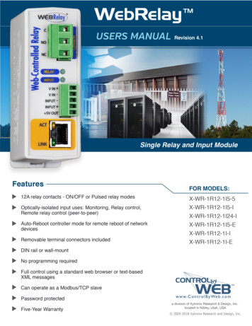
E-StopsTwo e-stop buttons, each with two normally closedmechanical contacts, are located at each of the lightcurtains. The e-stops use pulse testing outputs fromterminals 12 and 13 of the 440C-CR30 to check forpotential short circuit conditions.Pressing either E-stop stops both conveyors.Entrance/Exit E-stop* Solenoid monitoring23 2421 2200 01 02 03 04 05 06 07 08 09 10 11440C-CR30ABA1 A2 12 13 14 15 16 17 18 19 20 21440TMSRUEXXXX(Details ty19
BlueWhite (Aux)YellowRedGray (OSSD1)Pink (OSSD2)2 3 7 1 4 8 5 6BrownBrownGate SwitchesBlueWhite (Aux)YellowRedGray (OSSD1)Pink (OSSD2)2 3 7 1 4 8 5 6BlueWhite (Aux)YellowRedGray (OSSD1)Pink (OSSD2)Brown2 3 7 1 4 8 5 6Two non-contact SensaGuard Interlocks, each withdual OSSD outputs monitor the two safety gates.Since the SensaGuard interlocks have self-checkingOSSD outputs, pulse testing is disabled in the SMF9and SMF10 blocks.24V DC ComOpening either gate stops both conveyors. 24V DCBlueWhite (Aux)YellowRedGray (OSSD1)Pink (OSSD2)Gate 2BlueWhite (Aux)YellowRedGray (OSSD1)Pink (OSSD2)Brown2 3 7 1 4 8 5 6Gate 12 3 7 1 4 8 5 6Brown24V DC Com20Palletizer Functional Safety with relay and configurable relay solution.
24V DCGate 2Gate 3, etc2 3 7 1 4 8 5 62 3 7 1 4 8 5 6BlueWhite (Aux)YellowRedGray (OSSD1)Pink (OSSD2)BrownBrownBlueWhite (Aux)YellowRedGray (OSSD1)Pink (OSSD2)Brown2 3 7 1 4 8 5 6BlueWhite (Aux)YellowRedGray (OSSD1)Pink (OSSD2)Gate 124V DC Com 24V DCBlueWhite (Aux)YellowRedGray (OSSD1)Pink (OSSD2)Gate 2BlueWhite (Aux)YellowRedGray (OSSD1)Pink (OSSD2)Brown2 3 7 1 4 8 5 6Gate 12 3 7 1 4 8 5 6Brown21
Personnel AccessFunctional Safety DescriptionSensaguardnon-contactsafety interlockswitchRemoving key operates SRPCSPlacing key in key exchangeallows the door to be unlockedControl PanelInterlock SwitchAManual Control(MMI or Pushbuttons)STOP RESETSTOPRESETCBPERSONNEL DOOREDOnce the machine has beensignaled to stop, and themachine is in a quiescentstate the solenoid will allowthe primary key to be removedSolenoid release unit withprimary and secondarykey if required22EEach operator removes a key to preventrelocking of door while they are insideStainless steel ejector keyDual personnel access lock withspring-eject secondary keyPalletizer Functional Safety with relay and configurable relay solution.
At least one interlocked moveable guard (personnel door)shall be provided to allow operators and maintenance staff toenter the danger zone. The design of the personnel door or itsinterlocking device shall minimise the risk of the door closingaccidentally i.e. closing the door shall require a deliberateaction.The SRPCS for access shall be in accordance with the diagramleft, and shall operate as follows:A A BmanualC controlD shallE be supplied on the controlpanel which controls the machinery in the danger zone(this control can be by means of a pushbutton operator orHMI (Human Machine Interface). When this is operated themachinery in that danger zone shall assume a quiescent state.AB OnceC inDthis stateE and provided that all energy sourcesare isolated the control system shall allow the release of akey on the front of the control panel.Resetting and restarting shall be at the control panel but shallonly be possible after the correct reversal of the sequencedescribed above has been followed, and provided the feedbackloop containing the solenoid monitoring on the solenoidlocking switch is correct.Using this technique allows a maximum Performance Levelof d (PLd) in accordance with (EN) ISO 13849-1: 2015 If a PLeis requir
6 Palletizer Functional Safety with relay and configurable relay solution. Risk Assessment Requirements Based on the figure below, application of an applicable type-C standard may be applied, in this instance EN 415-4 as the machine is being produced for a market within Europe and as such references a