Transcription
IMPORTANT SAFETY INSTRUCTIONSSAVE THESE INSTRUCTIONSPLEASE READ THE ENTIRE CONTENTS OF THIS MANUAL PRIOR TOINSTALLATION AND OPERATION. BY PROCEEDING WITH LIFTINSTALLATION AND OPERATION YOU AGREE THAT YOU FULLYUNDERSTAND AND COMPREHEND THE FULL CONTENTS OF THIS MANUAL.FORWARD THIS MANUAL TO ALL OPERATORS. FAILURE TO OPERATE THIS EQUIPMENT AS DIRECTED MAY CAUSE INJURY OR DEATH.MAN REV A 01-03-11P/N 5900047INSTALLATION AND OPERATION MANUAL10,000 POUND CAPACITYSURFACE MOUNTEDTWO-POST IVINGThe shipment should be thoroughly inspected as soon as itis received. The signed Bill of Lading is acknowledgementby the shipping carrier as receipt of this product as listedin your invoice as being in a good condition of shipment. Ifany of these goods listed on this Bill of Lading are missingor damaged, do not accept goods until the shipping carriermakes a notation on the freight bill of the missing or damaged goods. Do this for your own protection.1BE SAFEYour new lift was designed and built with safety in mind.However, your overall safety can be increased with propertraining and thoughtful operation on the part of the operator.DO NOT operate or repair this equipment without readingthis manual and the important safety instructions showninside. Keep this operation manual near the lift at all times.Make sure that ALL USERS read and understand thismanual.1645 Lemonwood Dr.Santa Paula, CA. 93060, USAToll Free 1-800-253-2363Tel: 1-805-933-9970Fax: 1-805-933-9160wwwbendpak.com
10,000 POUND CAPACITY SURFACE MOUNTED TWO-POST LIFTSThis instruction manual has been prepared specifically for you. Your new lift is the product of over 40 years ofcontinuing research, testing and development; it is the most technically advanced lift on the market today.READ THIS ENTIRE MANUAL BEFORE INSTALLATION & OPERATION BEGINS.RECORD THE LIFT AND POWER UNIT INFORMATION HERE. YOU MAY FIND THIS INFORMATIONLOCATED ON THE SERIAL NUMBER DATA PLATE AND POWER UNIT DATA PLATEThis information will be required when calling for parts or warranty issues.Only replace parts with BendPak approved parts.PRODUCT WARRANTYBendPak two-post lifts are covered under warranty for five years on equipment structure, to be free of defects in materialand workmanship. Power units, hydraulic cylinders, and all other assembly components (such as cables, chains, valves,switches etc.) are warrantied for one year against defects in material or workmanship under normal use. BendPak Inc.shall repair or replace at its discretion, within the warranty period, those parts returned to the factory freight, prepaid, whichprove upon inspection to be defective. BendPak Inc. will pay labor costs for the first 12 months only on parts returned aspreviously described.The warranty does not extend to. defects caused by ordinary wear, abuse, misuse, negligence, shipping damage, improper installation, voltage orlack of required maintenance; damages resulting from purchaser’s neglect or failure to operate products in accordance with instructionsprovided in the owner’s manual(s) and/or other accompanying instructions supplied; normal wear items or service normally required to maintain the product in a safe operating condition; any component damaged in shipment; other items not listed but may be considered general wear parts; damage caused by rain, excessive humidity, corrosive environments or other contaminants.THESE WARRANTIES DO NOT EXTEND TO ANY COSMETIC DEFECT NOT INTERFERING WITH EQUIPMENTFUNCTIONALITY OR ANY INCIDENTAL, INDIRECT, OR CONSEQUENTIAL LOSS, DAMAGE, OR EXPENSE THATMAY RESULT FROM ANY DEFECT, FAILURE, OR MALFUNCTION OF A BENDPAK INC. PRODUCT OR THEBREACH OR DELAY IN PERFORMANCE OF THE WARRANTY.WARRANTY IS NOT VALID UNLESSWARRANTY CARD IS RETURNED.2
IMPORTANT NOTICEOWNER’S RESPONSIBILITYDo not attempt to install this lift if you have never beentrained on basic automotive lift installation procedures.Never attempt to lift components without proper liftingtools such as a forklift or cranes. Stay clear of any moving parts that can fall and cause injury. These instructions must be followed to insure proper installation andoperation of your lift. Failure to comply with these instructions can result in serious bodily harm and void productwarranty. Manufacturer will assume no liability for loss ordamage of any kind, expressed or implied resulting fromimproper installation or use of this product.To maintain the lift and user safety, the responsibility ofthe owner is to read and follow these instructions: Follow all installation and operation instructions. Make sure installation conforms to all applicable Local,State, and Federal Codes, Rules, and Regulations;such as State and Federal OSHA Regulations andElectrical Codes. Carefully check the lift for correct initial function. Read and follow the safety instructions. Keep themreadily available for machine operators. Make certain all operators are properly trained, knowhow to safely and correctly operate the unit, and areproperly supervised. Allow unit operation only with all parts in place andoperating safely. Carefully inspect the unit on a regular basis andperform all maintenance as required. Service and maintain the unit only with authorized orapproved replacement parts. Keep all instructions permanently with the unit andall decals on the unit clean and visible.PLEASE READ ENTIRE MANUALPRIOR TO INSTALLATION.DEFINITIONS OFHAZARD LEVELSIdentify the hazard levels used in this manual with thefollowing definitions and signal words:BEFORE YOU BEGINWatch for this symbol as it means: Immediate hazardswhich will result in severe personal injury or death.NOTIFY THE CARRIER AT ONCE if any hidden loss ordamage is discovered after receipt and request the carrierto make an inspection. If the carrier will not do so, preparea signed statement to the effect that you have notified thecarrier (on a specific date) and that the carrier has failed tocomply with your request.WARNING !IT IS DIFFICULT TO COLLECT FOR LOSS OR DAMAGEAFTER YOU HAVE GIVEN THE CARRIER A CLEARRECEIPT. Support claim with copies of the Bill of Lading,freight bill, invoice, and photographs, if available. BendPak’swillingness to assist in helping you process your claim doesnot make BendPak responsible for collection of claims orreplacement of lost or damaged materials.DANGER !Watch for this symbol as it means: Hazards or unsafepractices which could result in severe personalinjury or death.CAUTION !Watch for this symbol as it means: Hazards or unsafepractices which may result in minor personal injury,product or property damage.3
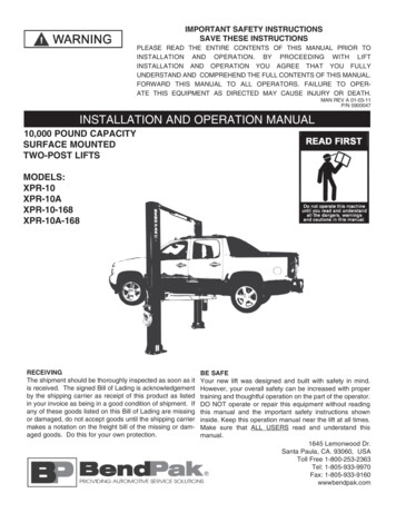
CLEARANCESXPR-10NOTE:SUBTRACT 6-1/2” FROM MINIMUMNEAREST WALL AND MINIMUMNEAREST BAY DIMENSION FORNARROW CONFIGURATION.NOTE: Lift measurements shown in WIDE configurationXPR-10ANOTE:SUBTRACT 6-1/2” FROM MINIMUMNEAREST WALL AND MINIMUMNEAREST BAY DIMENSION FORNARROW CONFIGURATION.NOTE: Lift measurements shown in WIDE configurationLIFT HEIGHT CLEARNACE NOTE: There must be a 1” MIN distance from top of lift to nearest obstruction.4
TABLE OF CONTENTSContentsPage No.Warranty / Serial Number Information . . . . . . . . . . . . . . . . . . . . . . . . . . . . . . . . . . . . . . . . . . . . . . . . . . . . . . . . . . . . . . 2Definitions of Hazard Levels . . . . . . . . . . . . . . . . . . . . . . . . . . . . . . . . . . . . . . . . . . . . . . . . . . . . . . . . . . . . . . . . . . . . . 3Owner’s Responsibility . . . . . . . . . . . . . . . . . . . . . . . . . . . . . . . . . . . . . . . . . . . . . . . . . . . . . . . . . . . . . . . . . . . . . . . . . 3Before You Begin . . . . . . . . . . . . . . . . . . . . . . . . . . . . . . . . . . . . . . . . . . . . . . . . . . . . . . . . . . . . . . . . . . . . . . . . . . . . . 3Clearances . . . . . . . . . . . . . . . . . . . . . . . . . . . . . . . . . . . . . . . . . . . . . . . . . . . . . . . . . . . . . . . . . . . . . . . . . . . . . 4Installer/Operator Agreement/ Protective Equipment . . . . . . . . . . . . . . . . . . . . . . . . . . . . . . . . . . . . . . . . . . . . . . . . . 6Introduction . . . . . . . . . . . . . . . . . . . . . . . . . . . . . . . . . . . . . . . . . . . . . . . . . . . . . . . . . . . . . . . . . . . . . . . . . . . . . . . . . . 7Safety / Warning Instructions . . . . . . . . . . . . . . . . . . . . . . . . . . . . . . . . . . . . . . . . . . . . . . . . . . . . . . . . . . . . . . . . . . . . . 7Tools Required . . . . . . . . . . . . . . . . . . . . . . . . . . . . . . . . . . . . . . . . . . . . . . . . . . . . . . . . . . . . . . . . . . . . . . . . . . . . . . . 8Step 1 / Selecting Site . . . . . . . . . . . . . . . . . . . . . . . . . . . . . . . . . . . . . . . . . . . . . . . . . . . . . . . . . . . . . . . . . . . . . . . . . . 8Step 2 / Floor Requirements . . . . . . . . . . . . . . . . . . . . . . . . . . . . . . . . . . . . . . . . . . . . . . . . . . . . . . . . . . . . . . . . . . . 8Concrete Specifications . . . . . . . . . . . . . . . . . . . . . . . . . . . . . . . . . . . . . . . . . . . . . . . . . . . . . . . . . . . . . . . . . . . . . . 8Assembly View / Description of Parts . . . . . . . . . . . . . . . . . . . . . . . . . . . . . . . . . . . . . . . . . . . . . . . . . . . . . . . . . . . . . . 9Step 3 / Post Preparation . . . . . . . . . . . . . . . . . . . . . . . . . . . . . . . . . . . . . . . . . . . . . . . . . . . . . . . . . . . . . . . 10-11Equalizer Cable Routing . . . . . . . . . . . . . . . . . . . . . . . . . . . . . . . . . . . . . . . . . . . . . . . . . . . . . . . . . . . . . . . . . . . . . . . . 12Step 4 / Site Layout / Floor Plan . . . . . . . . . . . . . . . . . . . . . . . . . . . . . . . . . . . . . . . . . . . 13-14Step 5 / Installing Power Side Post . . . . . . . . . . . . . . . . . . . . . . . . . . . . . . . . . . . . . . . . . . . . . . . . . . .14-15Step 6 / Installing Off Side Post . . . . . . . . . . . . . . . . . . . . . . . . . . . . . . . . . . . . . . . . . . . . . . . . . . . . . . . 15Step 7 / Mounting The Overhead Assembly . . . . . . . . . . . . . . . . . . . . . . . . . . . . . . . . . . . . . . . . . . . . . . . . . . . . 15-16Step 8 / Mounting The Hydraulic Power Unit . . . . . . . . . . . . . . . . . . . . . . . . . . . . . . . . . . . . . . . . . . . . . . . .16-17Step 9 / Installing the Safeties and Safety Cable . . . . . . . . . . . . . . . . . . . . . . . . . . . . . . . . . . . . . . . . . 17-18Step 10 / Installing Hydraulic Lines . . . . . . . . . . . . . . . . . . . . . . . . . . . . . . . . . . . . . . . . . . . . . . . . . . . . . . . . . . . . . 19Step 11 / Routing the Equalizer Cables . . . . . . . . . . . . . . . . . . . . . . . . . . . . . . . . . . . . . . . . . . . . . . . . . . . . . . . 19-20Step 12 / Installing Overhead Microswitch . . . . . . . . . . . . . . . . . . . . . . . . . . . . . . . . . . . . . . . . . . . . . . . . . . . . . . . . . 20-21Step 13 / Installing Power Unit Hose Assembly and Power Side Safety Cover . . . . . . . . . . . . . . . . . . . . . . . . . . . . . . . 21-22Step 14 / Installing the Lift Arms . . . . . . . . . . . . . . . . . . . . . . . . . . . . . . . . . . . . . . . . . . . . . . . . . . . . . . . 22-24Carriage Stop Bolt Installation Warning. . . . . . . . . . . . . . . . . . . . . . . . . . . . . . . . . . . . . . . . . . . . . . . . . . . . . . . . . 25Safety Label Placement Guidelines. . . . . . . . . . . . . . . . . . . . . . . . . . . . . . . . . . . . . . . . . . . . . . . . . . . . . . . . . 26Step 15 / Hydraulic Power Unit Hook-up . . . . . . . . . . . . . . . . . . . . . . . . . . . . . . . . . . . . . . . . . . . . . . . . . . . . . . . . . . . . . 27-29Step 16 / Lift Start Up Final Adjustments . . . . . . . . . . . . . . . . . . . . . . . . . . . . . . . . . . . . . . . . . . . . . . . . . . . . . . . . . . . . . 29Post Installation Checklist . . . . . . . . . . . . . . . . . . . . . . . . . . . . . . . . . . . . . . . . . . . . . . . . . . . . . . . . . . . . . . . . . . . . . . . . . 30Step 17 / Lubrication. . . . . . . . . . . . . . . . . . . . . . . . . . . . . . . . . . . . . . . . . . . . . . . . . . . . . . . . . . . . . . . . . . . . . . . . . . . 30Step 18 Bleeding the Cylinders . . . . . . . . . . . . . . . . . . . . . . . . . . . . . . . . . . . . . . . . . . . . . . . . . . . . . . . . . . . . . . . . . . . . . . . . . . . 30Optional Equipment Installation. . . . . . . . . . . . . . . . . . . . . . . . . . . . . . . . . . . . . . . . . . . . . . . . . . . . . . . . . . . . . . . . . . 31-32Step 19 / Operation/ Maintenance . . . . . . . . . . . . . . . . . . . . . . . . . . . . . . . . . . . . . . . . . . . . . . . . . . . . . . . . . . . . 33-43Troubleshooting Guide . . . . . . . . . . . . . . . . . . . . . . . . . . . . . . . . . . . . . . . . . . . . . . . . . . . . . . . . . . . . . . . . . . . . . . 44-47Maintenance Records . . . . . . . . . . . . . . . . . . . . . . . . . . . . . . . . . . . . . . . . . . . . . . . . . . . . . . . . . . . . 48Installation Form . . . . . . . . . . . . . . . . . . . . . . . . . . . . . . . . . . . . . . . . . . . . . . . . . . . . . . . . . . . . . . . . . . . . . . . . . . . . . 49Part Number Lists . . . . . . . . . . . . . . . . . . . . . . . . . . . . . . . . . . . . . . . . . . . . . . . . . . . . . . . . . . . . . . . . . . . . . . . . . 50-555
INSTALLER / OPERATORPLEASE READ AND FULLYUNDERSTAND. BY PROCEEDINGYOU AGREE TO THE FOLLOWING.Failure to follow Danger, Warning, and Caution instructions may lead to serious personal injury or death tooperator or bystander or damage to property. I have visually inspected the site where the lift is tobe installed and verified the concrete to be in good condition and free of cracks or other defects. I understand thatinstalling a lift on cracked or defective concrete couldcause lift failure resulting in personal injury or death.Please read the entire manual prior to installation.Do not operate this machine until yo
XPR-10 XPR-10A NOTE: Lift measurements shown in WIDE confi guration NOTE: Lift measurements shown in WIDE confi guration LIFT HEIGHT CLEARNACE NOTE: There must be a 1” MIN distance from top of lift to nearest obstruction. NOTE: SUBTRACT 6-1/2” FROM MINIMUM NEAREST WALL AND MINIMUM NEAREST BAY DIMENSION FOR NARROW CONFIGURATION. NOTE: