Transcription
Stairs lightingcontrollerSTX-1791The STX-1791 controller is used for staticlighting control of stairs. Its operation consists inslowly switching on the lighting of entire stairs andafter a set time, slowly dimming the lighting.You can set five parameters of the controlleryourself: brightness in the on state, brightnessin the off state (so-called backlight), speed oflighting up (igniting) stairs, speed of blanking(dimming) and lighting time.It is adapted to control LED MONO strips placed in steps or LED spots embedded in the wallabove the steps. You can also control other lightingof stairs, eg 12V ceiling lamps.The lighting can be started in the simplest version by pressing the button on the wall connecteddirectly to the controller or by applying (additionally) a sensor (infrared, movement, pressure, etc.)detecting the moment of entry of the person onthe stairs. If during the lighting of the stairs the button is pressed again or there is an impulse from themotion sensor, the lighting time will be extended.Controller installation:The controller is best placed in the electrical cabinet (switchboard) together with the power supplyand possibly other controllers. The INJ and GND input terminals should be connected with buttons ormotion detectors, with the help of which stairs lighting can be switched on and off. Note: Do not use abistable switch such as in a normal light installation - use a button such as a bell or roller blind. The othertwo terminals on the front of the 12V and 5V controllers are used to power the motion detectors. Donot connect power supply to them!The LED strips placed on the steps are connected to the LED (-) terminal of the controller and tothe plus voltage of 12V. The power supply voltage ( ) to the controller’s 12V terminal, and the minuspower to the GND terminal (three terminals on the back of the controller).www.stairslight.com
LED lightingSTX-1791 can control the backlight realized with LED strips or 12V lamps (but not 230V!). LED stripsare generally mounted under the step, and lamps on the side of the step. It is only necessary to checkif the lamps are dimmable like tapes. Connecting the illuminating elements show the next drawings.LED stripsA popular way to highlight the stairs is to use LED strips. In the case of the STX-1791 controller, usesingle-color tapes (MONO). Color does not matter. The controller STX-1793 and STX-1796 are intendedfor the control of color tapes (RGB). The standard supply voltage of LED strips is 12V. The controllercan also be connected to LED strips powered by 24V, but due to the electronics of the controller, thisvoltage should not be exceeded.Electrical installation of stair steps - LED stripsTLED strips are usually placed under the steps. Points ( ) should be connected together to one wireand the points (–) should be connected together to the other wire. Both wires with a cross-section of1.5mm2 are fed to the controller. You can also bring to the controller, separately one pair of wires fromeach LED strip (0.5mm2). Both solutions are equivalent.www.stairslight.com
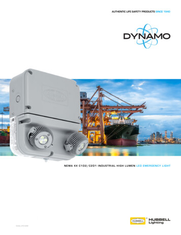
Diagram of connecting the controller to LED strips.The diagram above shows the connection of the controller to stairs consisting of 18 steps and twohandrails. All ( ) LED strips are connected together and all (–) LED strips are connected together. Plusled strip is connected to the plus of the power supply, and minus LED strips to the driver output (LED).Controller buttons and sensors are connected to the controller input. You can also connect the samebuttons or sensors themselves. The 12V output is used to power the sensors. Several sensors andseveral buttons can be connected to the controller, depending on the needs and arrangement of the stairs.ControlController input works on a short to ground. All you have to do is connect a mechanical button (nota switch) to start the driver after pressing it briefly. One contact of the button should be connected to thecontroller’s input and the other to ground (minus 12V). All the drawings show this solution.You can also run the controller using other components or devices, most often using motion sensors.Motion sensors found on the local market are in two versions: 230V mains voltage and 5 or 12V mainsvoltage. Do not connect these sensors directly to the controller input, because, especially in the case of230V sensors, it will cause in the best case the wrong operation of the controller, and in the worst case,its total damage.www.stairslight.com
Before installing the sensors, their parameters must be set. The most important is the length of thepulse (the time the sensor is switched on), which should be set to the minimum and can not exceed 15seconds (preferably about 1-5 seconds - check before purchasing). The second parameter that can beset in the sensor is its sensitivity or range. This parameter should be set experimentally so that the switchon takes place reliably and at the right moment.Some sensors have different operating modes to choose from. The triggering mode should be turnedoff, because in this mode the sensor keeps the impulse during the whole time of the person’s presencein its range and thus the pulse becomes too long for the controller’s requirements.Sensors operating in the 230V grid require the use of relays in order to separate the 230V circuitfrom the controller inputs. Low voltage sensors will almost certainly need a special adapter to match thesensor signal to the controller’s requirements. The following diagrams and descriptions explain how toconnect the most common types of sensors on the market. If it is necessary to use a different type ofsensor, please contact us in order to agree on the method of connecting the sensor.We urge you to use our sensors. They can be connected directly to the controller and havethe appropriate time parameters.Motion sensors with a voltage of 230 VA typical motion sensor (230V) is a standard size module and is connected to the installation box.It has regulatory elements (time, sensitivity, etc.) and usually three contacts for wires. Two are pluggedinto a 230V network, and the third wire is used to power the receiver (the lamp) and is marked with anappropriate symbol. Before installing the sensor, carefully read the instructions.Some motion sensors have abuilt-in additional twilight sensor.Depending on the sensitivity settingsit can be inactive in strong light. Thus,illumination of the stairs does not turnon during the day. However, this maycause problems - if it rains, the twilight sensor will lighten the stairs. Byadjusting the sensitivity, you can try toprevent this. We can recommend our230V sensor CRN-5491, modified towork with our controller:.Motion sensor for 110-230V - CRN 5491The next diagram is one of a typical motion sensor (230V) connected to the controller. Relays mustbe used! Relay coil voltage must be set at 230V, because this voltage is supplied from the motion sensor.Connect input 1 or 2 and (-) of 12V to the contacts of the relay NO (normally open) and CO (common),.We recommend the assembly to be done very carefully. If the connections are made erroneously, thecontroller will be damaged.www.stairslight.com
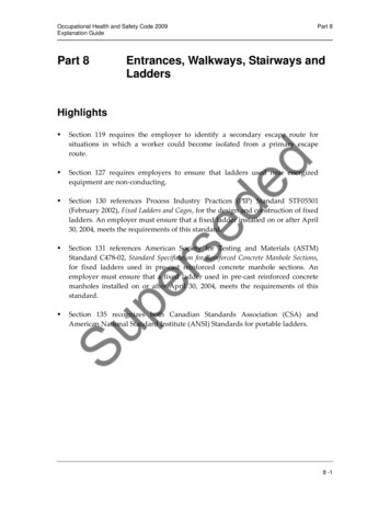
Installation diagram for connecting 230V motion detectors to the controllerThe relays used to separate 230V circuitfrom the controller may be of any type. Werecommend the relays to be mounted on T-35bus, the same as the controller. Their use helpswith the installation.Photo to the left shows our product STP4811 — a set of two relays in a single-rail caseT-35. This set makes it possible to separate230 V voltage coming simultaneously from twomotion sensors.Set of two relays STP-4811www.stairslight.com
Assembly diagram of motion sensors CRN-5891 connected to the controller by a set of relays STP-4811NOTE: The knob „Time” in the sensors must be set to the minimum position!Installation of motion sensors inorder to work properly is extremelydifficult. The visualization presentedhere may be helpful.We recommend the sensor tobe tilted down, so it „sees” only aportion of the first step. The top ofthe Fresnel lens should be coveredwith an opaque material. If the motionsensor does not have a built-in lightsensor, at least a small, steady source of light over the sensor should beadded to light up the field observedby the sensor.The motion sensor mounted on the wallwww.stairslight.com
Motion sensors for 12V voltageYou can also use miniature motion sensors operating at a low voltage such as 12V. We offera sensor with the symbol CRN-5481. Voltage of the sensor is identical to the LED supply voltage,which greatly simplifies installation of the entire system.Sensor dimensions: plate: 32.5 x 23.5 mm, thediameter of the bowl: 23mm. The sensor has anadjustable impulse length and sensitivity.The sensor can be connected directly to thecontroller input. It is important that the sensor, theadapter and the driver have been combined in theright way, according to the following pictures anddiagrams.Miniature motion sensorOn the back of the sensor is a connector for connecting wires leading to the controller. To facilitateassembly, to each sensor is added the connector tosoldering wires. You should keep the correct orderof wires according to the description on the sensorconnector.Sensor with a properly placed adapterThe view of the sensor back sideIt is recommended to use colored cables withthe smallest possible diameter, eg. telephone cablebundles. Please note that any mistake in wiring, especially power can damage the sensor or controller.Sensor socket and plugwww.stairslight.com
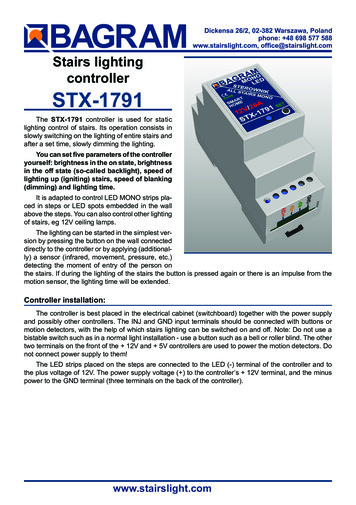
The diagram below shows exactly how the whole set is built with the use of 12V motion sensors.Installation diagram: 12V motion sensors connected to the controllerBefore mounting the sensors, please set their time of action and sensitivity to a minimum. In thecase of sensors with a jumper used to select the operating mode with or without triggering, choose theposition “non-repeatable trigger.”These two sets of adapters with sensors should be mounted in their appropriate place by the sideof the first and the last step.The controller can handle additional input located on the mezzanine. In such a case, an additionalmotion sensor (or an additional push button) should be placed so as to detect the entrance a person tothe staircase mezzanine, but so it does not react to people walking up the stairs.After detecting a person entering the stairs to the mezzanine, the controller will immediately start thelighting of the whole staircase and turn it off after approx. 20 seconds. The diagram on the neighboringside shows such a solution.www.stairslight.com
Setting the motion sensorsThis is one of the most difficult operations — it requires patience and precision. First of all, adjustthe sensitivity of the sensor in order to have it react effectively to a person entering the staircase. Thesecond problem to solve is that the sensor should not react to a person coming down the stairs - that itdoes not re-activate the fading lighting of the stairs. The best way is to cover the sensor hemispheresrespectively. Of course, the arrangement of the sensors is also very important — usually they are placedon the right side of the stairs looking in the direction of movement (‘right-hand traffic’). Some sensorshave an additional adjustable parameter - the so-called ‘dead time’. It is the time measured after an impulse, during which the sensor does not respond to the next person entering the field of its operations.When the mentioned parameters are adjusted patiently, the sensors will function properly, providing asatisfactory lighting of the stairs.Adjusting the controllerSetting the parameters should be performed only when strictly necessary, after reading the followingdescription carefully.In total, there are 5 parameters to change.To start the parameter setting mode, press and hold the SET button until the green LED fades out.Release the button to go on to the controller parameter setting mode. A few seconds flickering of the LED(and first step) corresponds to each parameter. You can set or change 5 parameters, and therefore therewill be five consecutive flickers of the LED. To select a specific parameter to be changed, you shouldcount each flicker and then, after a suitable number of flickers, press the SET button. If you do not wantto change a parameter, skip the flickering without pressing the button. If at the parameter setting modethe SET button is not pressed, none of the parameters will change.Adjusting controller parameters diagramThe principle of setting the parameters is as follows: setting each parameter is indicated by a rapidflickering of the green LED (and first step). If during this flickering the SET button is pressed and held,then, depending on the parameter, you will see from one to several dozens of slow LED pulsees. Settingthe parameter takes place after a release of the button after the desired number of pulsees or just afterthe end of the flickering. During the flickering, if the SETUP button is not pressed, after a short time of theLED fading out, flickering of the next parameter will appear and so on until the end of the setting mode. Ifthe given flicker is omitted, the corresponding parameter will not be changed. This allows you to set onlyone parameter, without any of the others. Notice: if the SET button is pressed during the flickering andreleased immediately after it, but before the first pulse, the parameter will return to the factory setting.www.stairslight.com
After setting the selected parameter, the controller immediately returns to a stand-by state, waiting fora signal from pulse sensors or push buttons. There are no flickers for other parameters. To set anotherparameter, use of the SET button again.Description of parametersTo go to the setting of fixed parameters, press and hold the SET button until the LED goes out. Aftera while, the LED will flash several times indicating the possibility of setting parameters.Flickering 1: Setting the maximum brightness of the stairs. Pressing the button during the first flickering will allow you to set the maximum value (ON state). The button should be pressed and held untilthe lighting of the stairs changes cyclically its brightness. During this time the diode is slowly flashing.Releasing the button at the appropriate brightness sets it as a constant maximum brightness. If you wantto immediately set the value to the maximum possible, you should release the button immediately afterthe first flickering. Factory set to the maximum.Flickering 2: Setting the minimum brightness (OFF state). The lighting of the stairs does not have tofade to zero. For safety reasons, especially at night, it is recommended to set a certain minimum valuefor the stairs lighting. The controller allows setting such brightness (backlight). Press the button duringthe second flickering and keep it until the brightness of the light changes smoothly. Releasing the buttonat the right time set the required constant minimum brightness. If you want the light to turn off completely,let go of the button immediately after flickering. Factory set to minimum stair lighting.Flickering 3: Set the brightening time for diodes. Press the button during this flickering and hold untilthere are slow pulses. The number of flashes is proportional to the time of lighting (4 flashes are 1 secof brightening). It is enough to hold the button for the right number of flashes. Releasing the button justafter the end of flickering, sets the time to zero, i.e. the LEDs will light up immediately without smoothlightening. Factory set to 1 sec.Migotanie 4: Setting the dimming time of diodes. Press the button during this flickering and holduntil there are slow pulses. The number of flashes is proportional to the dimming time (4 flashes are 1second dimming). It is enough to hold the button for the right number of flashes. Releasing the buttonjust after the end of flickering sets the time to zero, i.e., the LEDs will go off immediately, without smoothdimming. Factory set to 4 seconds.Migotanie 5: Setting the timer time. Here you can set the time after which the stairs will be dimmed.Press the button during this flickering and hold until there are slow pulses. Each pulse means one second. Releasing the button, eg after 5 pulses, will cause the staircase lighting to turn off after 5 seconds.Factory set to 20 seconds.After the last process, the controller goes directly to the waiting mode for the trigger pulse.www.stairslight.com
the stairs. If during the lighting of the stairs the button is pressed again or there is an impulse from the motion sensor, the lighting time will be extended. Controller installation: The controller is best placed in