Transcription
Service TrainingSelf Study Program 850123The 7-speed Double-Clutch Transmission 0AMDesign and Function
Volkswagen Group of America, Inc.Volkswagen AcademyPrinted in U.S.A.Printed 08/2012Course Number 850123 2012 Volkswagen Group of America, Inc.All rights reserved. All information contained in this manualis based on the latest information available at the time ofprinting and is subject to the copyright and other intellectualproperty rights of Volkswagen Group of America, Inc., itsaffiliated companies and its licensors. All rights are reservedto make changes at any time without notice. No part of thisdocument may be reproduced, stored in a retrieval system,or transmitted in any form or by any means, electronic,mechanical, photocopying, recording or otherwise, normay these materials be modified or reposted to other siteswithout the prior expressed written permission of thepublisher.All requests for permission to copy and redistributeinformation should be referred to Volkswagen Group ofAmerica, Inc.Always check Technical Bulletins and the latest electronicrepair information for information that may supersede anyinformation included in this booklet.Trademarks: All brand names and product names used inthis manual are trade names, service marks, trademarks,or registered trademarks; and are the property of theirrespective owners.
ContentsIntroduction . . . . . . . . . . . . . . . . . . . . . . . . . . . . . . . . . . . . . . . . . . . . . . . . 1Selector Lever . . . . . . . . . . . . . . . . . . . . . . . . . . . . . . . . . . . . . . . . . . . . . . 4Transmission Design . . . . . . . . . . . . . . . . . . . . . . . . . . . . . . . . . . . . . . . . 10Mechatronic Module . . . . . . . . . . . . . . . . . . . . . . . . . . . . . . . . . . . . . . . . 30Electrohydraulic Control Unit. . . . . . . . . . . . . . . . . . . . . . . . . . . . . . . . . 32Oil Circuit – Hydraulic System . . . . . . . . . . . . . . . . . . . . . . . . . . . . . . . . 33Transmission Management System . . . . . . . . . . . . . . . . . . . . . . . . . . . 48Service . . . . . . . . . . . . . . . . . . . . . . . . . . . . . . . . . . . . . . . . . . . . . . . . . . . 65Knowledge Assessment . . . . . . . . . . . . . . . . . . . . . . . . . . . . . . . . . . . . . 67NoteThis Self-Study Program provides informationregarding the design and function of newmodels.This Self-Study Program is not a Repair Manual.Important!This information will not be updated.For maintenance and repair procedures,always refer to the latest electronicservice information.iii
Page intentionally left blank
IntroductionThe New 7-Speed Double-Clutch Transmission from VolkswagenThe 7-speed double-clutch transmission 0AM is based on the 02E DSG transmission. It offers the same comfortand shifting characteristics of the 02E DSG. It has been designed for engines with a torque of up to 184 lb/ft(250 Nm) of torque.The DSG transmission economy is on a par with manual transmission vehicles. The DSG transmission hassucceeded in reducing fuel consumption below that of manual transmissions using technical innovations. Thisreduction in fuel consumption makes a significant contribution towards lowering emissions.In this SSP, you will learn how the new 0AM double-clutch transmission functions and the technical highlightsthat help to reduce fuel consumption.We hope you enjoy reading it.Application in the Jetta HybridAlthough Volkswagen has used this transmission in vehicles for many years, the first application for the NorthAmerican market is the 2013 Jetta Hybrid. Some aspects of this SSP are different for hybrid applications, and thisSSP does not cover those differences.Please refer to ElsaWeb for the specific changes for use in the Jetta Hybrid.1
IntroductionThe new 0AM DSG is the: First transverse 7-speed transmission First double-clutch transmission with dry double clutchMechatronic UnitS390 060Double ClutchThe dry double clutch has an extensive impact on the entire transmission concept. In comparison with the directshift transmission 02E, efficiency has been considerably improved. This improved efficiency makes a significantcontribution towards lowering consumption and emissions.2
IntroductionDesign Features Modular design of the transmission: The clutch, mechatronic unit and transmission each form one unit Dry double clutch Separate oil circuit, mechatronic unit and mechanical transmission, with lifetime fillings Seven speeds on four shafts No oil/water heat exchangerMechatronic UnitDouble ClutchS390 003Technical DataDesignation0AMWeightApprox. 154 lb (70 kg) including clutchTorque184 ft lbs (250 Nm)GearsSeven Forward Speeds, One Reverse GgearSpread8.1Operating ModeAutomatic and Tiptronic ModesTransmission Fluid Volume1.7L - G 052 171Mechatronic Unit Fluid Volume1.0L Central Hydraulic/Power Steering Box Fluid G 004 0003
Selector LeverActuationThe selector lever is the same as in normalautomatic transmission vehicles. The double-clutchtransmission also offers the option of shifting usingTiptronic.Release ButtonAs with automatic transmission vehicles, the selectorlever has with a selector lever lock and an ignition keywithdrawal lock.The selector lever positions are:P - ParkTo move the selector lever from this position, theignition must be ON and the foot brake must bedepressed. The release button on the selector levermust also be pressed.R - Reverse GearThe release button must be pressed to engage thisgear.N - Neutral PositionIn this position, the transmission is in neutral. If theselector lever is set to this position for a long time,the foot brake must be depressed again to move itfrom this position.D - Drive PositionIn this drive position, the forward gears are shiftedautomatically.S - SportAutomatic gear selection is carried out according toa "sporty" characteristic curve, which is stored in thecontrol module.4S390 005
Selector LeverDesign of the Selector LeverE313 Selector LeverF319 Selector Lever Park Position Lock SwitchHall sensors in the selector lever register the selectorlever position and make this information available tothe mechatronic unit via the CAN bus.If the selector lever is in the "P" position, the signal issent to the J527 Steering Column Electronics ControlModule. The control module requires this signal tocontrol the ignition key withdrawal lock.N110 Shift Lock SolenoidThe solenoid locks the selector lever in the "P" and"N" positions. The solenoid is controlled by the J587Selector Lever Sensor System Control Module.Locking Pin Latch "P"F319E313Locking Pin Latch "N"N110S390 007Hall Senders for Detectingthe Selector Lever Position5
Selector LeverN110 Shift Lock SolenoidHow It Works:N110CompressionSpringSelector Lever Locked in "P" PositionIf the selector lever is set to "P", the locking pin islocated in locking pin latch "P". This prevents thelocking lever from being moved unintentionally.Locking PinLatch for "P"Locking PinS390 008Selector Lever Released:After switching on the ignition and actuating thefoot brake, the J587 Selector Lever Sensor SystemControl Module supply the N110 Shift Lock Solenoidwith current. As a result of this, the locking pin iswithdrawn from the locking pin latch "P".The selector lever can now be moved to the driveposition.S390 009Selector Lever Locked in "N" PositionIf the selector lever is set to the "N" position forlonger than 2 sec., the control unit supplies thesolenoid with current. As a result of this, the lockingpin is pressed into locking pin latch "N". The selectorlever can no longer be unintentionally moved into agear. The locking pin is released when the brake isactuated.Locking PinLatch for "N"S390 0106
Selector LeverEmergency ReleaseIf the voltage supply to the N110 Shift Lock Solenoidfails, the selector lever cannot be moved becauseselector lever lock "P" remains activated in the eventof a power failure.By mechanically "pressing in" the locking pin witha narrow object, the lock can be released and theselector lever can be "emergency released" to the "N"position.The vehicle can be moved again.S390 0117
Selector LeverIgnition Switch Key Lock SolenoidThe ignition key withdrawal lock prevents the ignitionkey from being turned back to the removal position ifthe parking lock is not engaged.N376It functions electromechanically and is controlledby the J527 Steering Column Electronics ControlModule.The J527 detects the open switch. The N376Ignition Switch Key Lock Solenoid is not suppliedwith current. The compression spring in the solenoidpushes the locking pin into the release position.S390 012How It Works:With the selector lever in park position the ignition is switched off. If the selector lever is set to the park position,the F319 Selector Lever Park Position Lock Switch is opened.Retaining LugCompression Spring"Ignition Off"Locking PinS390 0138
Selector LeverHow It Works:Selector lever in drive position the ignition isswitched on.In the locked position, the locking pin prevents theignition key from being turned back and withdrawn.If the selector lever is set to the drive position, theF319 Selector Lever Park Position Lock Switch isclosed.Only when the selector lever is pushed into the parkposition does the selector lever locked in position"P" switch open and the control unit switches off thecurrent supply to the solenoid.The steering column electronics control unit thensupplies the N376 Ignition Switch Key Lock Solenoidwith current.The locking pin is then pressed back by thecompression spring. The ignition key can be turnedfurther and can be removed.The locking pin is pushed into the locked positionbecause the solenoid overcomes the force of thecompression spring."Ignition On"N376S390 0149
Transmission DesignBasic PrincipleGears 1, 3, 5 and 7 are shifted via clutch K1 via geartrain half 1 and output shaft 1. Gears 2, 4, 6 andreverse gear are actuated via clutch K2 and gear trainhalf 2 and output shafts 2 and 3.In principle, the double-clutch transmission consistsof two independent halves.In terms of function, each half is designed as amanual transmission. A clutch is assigned to eachhalf.One gear train half is always connected. The nextgear can already be shifted in the other gear trainhalf, because the clutch for this gear is still open.The two clutches are dry clutches. They are openedand closed and controlled by the mechatronic unitdepending on the gear to be shifted.A conventional, manual transmission synchronizerand shift unit is assigned to each gear.Basic SchematicGear Train Half 2Output Shaft 3Output Shaft 2Drive Shaft 2R642K2K1753Engine Torque1Drive Shaft 1Output Shaft 1Gear Train Half 1S290 01510
Transmission DesignTorque InputTorque is transferred from the dual-mass flywheel, which is secured to the crankshaft, to the double clutch. Thedual-mass flywheel is equipped with inner teeth that engage in the outer teeth on the double clutch carrier ring.From there, the torque is transmitted to the double clutch.Carrier RingDrive Shafts 1 and 2Outer TeethInner TeethDouble ClutchDual-Mass FlywheelS390 06411
Transmission DesignDouble Clutch and Torque CurveThe double clutch is located in the bell housing. It consists of two conventional clutches, which combined form adouble clutch. During the remainder of this SSP, the clutches are referred to as K1 and K2.Clutch K1 transfers the torque to drive shaft 1 via splines. From drive shaft 1, the torque for gears 1 and 3 istransferred to output shaft 1, and the torque for gears 5 and 7 is transferred to output shaft 2.Clutch K2 transfers the torque to drive shaft 2 via splines. It transfers the torque for gears 2 and 4 to output shaft1 and the torque for 6th gear and reverse gear to output shaft 2. Using the reverse gear intermediate gear R1,the torque is then passed on to reverse gear R2 on output shaft 3.All three output shafts are connected to the differential final drive gear.Dual-Mass FlywheelClutch K2Output Shaft 3Clutch K1Output Shaft 2Drive Shaft 1Drive Shaft 2Output Shaft 1Final Drive Gear1 7 1st to 7th gearsR1 reverse gear intermediate gearR2 reverse gear12DifferentialS390 016
Transmission DesignDouble Clutch Drive PlateFrom the carrier ring, the torque is transferred to the drive plate in the double clutch. For this to take place, thecarrier ring and drive plate are joined firmly together. The drive plate is mounted on drive shaft 2 as an idler gear.How It Works:Carrier RingIf one of the two clutches is actuated, the torqueis transferred from the drive plate onto the relevantclutch plate and onwards onto the correspondingdrive shaft.Carrier RingS390 065Drive PlateDrive Shafts 1 and 2Dual-Mass FlywheelS390 067Clutch K2Clutch K113
Transmission DesignClutchesTwo independent, dry clutches operate in the double clutch. They each transfer the torque to one gear train half.Two clutch positions are possible: When the vehicle is stopped and idling, both clutches are open. During vehicle operation, only one of the two clutches is ever closed.Clutch K1Clutch K1 conducts the torque for gears 1, 3, 5 and 7 to drive shaft 1.Clutch K1 Not ActuatedDrive Shaft 1S390 01714
Transmission DesignHow It Works:To actuate the clutch, the engaging lever presses the engagement bearing onto the diaphragm spring. At severalcontact points, this compression movement is transformed into a tension movement.As a result, the pressure plate is pulled onto the clutch plate and the drive plate. The torque is then transferred tothe drive shaft.The engaging lever is actuated via N435 Sub-Transmission 1 Valve 3 by the hydraulic clutch actuator for K1.Diaphragm SpringClutch K1 ActuatedEngagementBearingPressure PlateS390 066Drive PlateDiaphragmSpringClutch PlateEngaging LeverS390 08715
Transmission DesignClutch K2Clutch K2 transfers the torque for gears 2, 4, 6 and R to drive shaft 2.Drive Shaft 2S390 01816
Transmission DesignHow It Works:Clutch K2If the engaging lever is actuated, the engagement bearing presses against the pressure plate diaphragm spring.Because the diaphragm spring is supported by the clutch housing, the pressure plate is pressed against the driveplate and the torque is transferred onto drive shaft 2. The engaging lever is actuated via N439 Sub-Transmission 2Valve 3 by the hydraulic clutch actuator for K2.Drive PlatePressure PlateSupport PointClutch K2 ActuatedDiaphragm SpringEngagementBearingClutch PlateEngaging LeverS390 08817
Transmission DesignDrive ShaftsThe drive shafts are located in the transmissionhousing. Each drive shaft is connected to a clutchvia splines. These transfer the engine torque ontothe output shafts according to the gear which isengaged.Drive shaft 2 is hollow. Drive shaft 1 runs throughhollow drive shaft 2. Ball bearings are mounted inthe transmission case.S390 046Drive Shaft 1Drive Shaft 2SplineBall Bearing18S390 019
Transmission DesignDrive Shaft 2Due to its installation position, we will cover drive shaft 2 before drive shaft 1.Gear for G612Bearing4th/6th GearsS390 0202nd/R GearsDrive shaft 2 is a hollow shaft. It is connected to K2 via splines. Drive shaft 2 is used to shift gears 2, 4, 6 and R.To record the transmission input speed, this shaft has the gear for G612 Transmission Input Speed Sensor 2.Drive Shaft 1G632Bearing1st Gear5th Gear3rd Gear7th GearS390 021Drive shaft 1 is connected to clutch K1 via splines. It is used to shift gears 1, 3, 5 and 7. To record thetransmission input speed, this shaft has the impulse wheel for G632 Transmission Input Speed Sensor 1.Please note that a strong magnet may destroy the impulse wheel for drive shaft 1.19
Transmission DesignOutput ShaftsInstallation Position in theTransmissionThe transmission has three output shafts.(View from the left – shown elongated)Depending on the gear which is engaged, the enginetorque is transferred from the drive shafts to theoutput shafts.An output gear is located on each output shaft.S390 023Output Shaft 11st Gear3rd Gear4th Gear2nd GearOutput GearBearingBearingSliding Sleeve,Gears 1/3Sliding Sleeve,Gears 2/4S390 022The following are located on output shaft 1: The selector gears for gears 1, 2 and 3; the 3 gears are 3x’s synchromeshed. The selector gear for 4th gear; the 4th gear is 2x’s synchromeshed.20
Transmission DesignInstallation Position in theTransmission(View from the left – shown elongated)S390 025Output Shaft 2R Gear 15th Gear7th GearSliding Sleeve,Gears 5/76th GearSliding Sleeve,Gears 6/RR Gear 2Output GearS390 024The following are located on output shaft 2: The 2-fold synchromeshed selector gears for gears 5, 6 and 7, and The intermediate gears R gear 1 and R gear 2 for reverse gear.21
Transmission DesignOutput Shaft 3Installation Position in theTransmission(View from the left – shown elongated)Parking Lock GearS390 027Gear Wheel for R GearBearingOutput GearBearingSliding SleeveThe following are located on output shaft 3: The 1-fold synchromeshed selector gear for R gear The parking lock gear22S390 026
Transmission DesignDifferentialInstallation Position in theTransmission(View from the left – shown elongated)Final Drive GearS390 029S390 028The differential transfers the torque onwards to the vehicle wheels via the drive shafts.23
Transmission DesignParking LockA parking lock is integrated into the DSG to ensure that a parked vehicle does not roll away.The locking pin is engaged purely mechanically via a Bowden cable between the selector lever and the parkinglock lever on the transmission.The Bowden cable is used exclusively to actuate the parking lock.Connection Ball for ParkingLock Bowden CableHold-Down DeviceDetent SpringLocking PinActuation PinPre-Tensioning SpringReturn Spring forLocking PinParking Lock GearS390 03024
Transmission DesignFunctionParking Lock Not Actuated,(Selector Lever Position R, N, D, S)Hold-DownDeviceDetent SpringWhen the parking lock is not actuated, the cone ofthe actuation pin lies on the holding-down device andthe locking pin.The parking lock is held in the non-actuated positionby a locking device.Actuation PinLocking PinS390 061Parking Lock Sctuated, Locking Pin Not Engaged(Selector Lever Position P)By actuating the parking lock, the cone of theactuation pin is pressed against the hold-downdevice and the locking pin. As the hold-down deviceis stationary, the locking pin moves down. If itencounters a tooth on the parking lock gear, the pretensioning spring is tensioned.Locking DeviceThe actuation pin is held in this position by thelocking device.Pre-Tensioning Spring,TensionedS390 062Parking Lock Actuated, Locking Pin Engaged(Selector Lever Position P)(Locking Pin Engaged)If the vehicle continues to move, the parking lockgear also rotates.As the actuation pin is pre-tensioned, it automaticallypushes the locking pin into the next tooth space onthe parking lock gear.Tooth ofLocking Pin Engagedin Parking Lock GearPre-Tensioning Spring,RelaxedActuation Pinin End PositionS390 06325
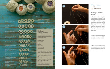
Transmission DesignGear SynchronizationA synchromesh with locking pieces is used for all gears to synchronize the different speeds when changinggears. Depending on the shifting load, the gears are synchronized between one and three times.GearSynchromeshSynchronizer Ring Material1st to 3rdThree synchronizersBrass with molybdenum coating4thTwo synchronizersBrass with molybdenum coating5th to 7thOne synchronizerBrass with molybdenum coatingROne synchronizerBrass with molybdenum coatingThe figure shows the synchromesh design for 2nd, 4th and R gears.Outer ring(intermediatering)Selector ForkIntermediate RingFirmly Connected(Welded)SynchronizerRing(inner)Selector gear2nd gearSynchronizerRing(outer)Synchronising HubSliding SleeveLocking piecesSynchronizer Ring(outer)Clutch SplinesSynchronizer Ring(inner)S390 081Selector Gear4th GearSliding SleeveSelector Gear R GearS390 082Synchronizer RingLocking PiecesSynchronising Hub26
Transmission DesignPower Transmission in the GearsTorque is transmitted into the transmission by either clutch K1or K2. Each clutch drives a drive shaft. Drive shaft 1 is driven byclutch K1 and drive shaft 2 is driven by clutch K2.Power is transmitted to the differential via: output shaft 1 for gears 1, 2, 3, and 4, output shaft 2 for gears 5, 6 and 7, and output shaft 3 for reverse gear and the parking lock.S390 033S390 0341st GearR GearClutch K1Drive Shaft 1Output Shaft 1DifferentialClutch K2Drive Shaft 2Output Shaft 3DifferentialThe change in rotational direction for reverse gear iscarried out by output shaft 3.For greater clarity, power transmission is shown schematically in "elongated" form.27
Transmission Design2nd GearClutch K2Drive Shaft 2Output Shaft 1DifferentialS390 0353rd GearClutch K1Drive Shaft 1Output Shaft 1DifferentialS390 0364th GearClutch K2Drive Shaft 2Output Shaft 1DifferentialS390 03728
Transmission Design5th GearClutch K1Drive Shaft 1Output Shaft 2DifferentialS390 0386th GearClutch K2Drive Shaft 2Output Shaft 2DifferentialS390 0397th GearClutch K1Drive Shaft 1Output Shaft 2DifferentialS390-04029
Mechatronic ModuleJ743 DSG Transmission MechatronicThe mechatronic unit controls all transmission functions. It combines the electronic control unit and theelectrohydraulic control unit into a single component.The mechatronic unit is an autonomous unit. It has a separate oil circuit, which is independent of the oil circuitfor the mechanical transmission.The advantages of this autonomous, compact unitare: All sensors (except one) and actuators arecontained in the mechatronic unit. The hydraulic fluid is specifically adapted to therequirements of the mechatronic unit. Due to the separate oil circuit, no foreign materialfrom the mechanical transmission enters into themechatronic unit. Good low-temperature behavior, as nocompromise has to be made with therequirements of the transmission in terms ofviscosity behavior.Mechatronic UnitS390 04130
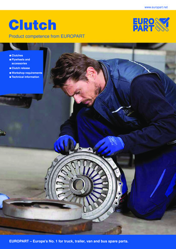
Mechatronic ModuleThe electornic control unit is the central transmission control unit. All sensor signals and all signals from othercontrol units come together here, and all actions are performed and monitored by it. Eleven sensors areintegrated into the electronic control unit; only the G182 Transmission Input Speed Sensor is located outside ofthe control unit. The electronic control unit hydraulically controls and regulates eight solenoid valves for shiftingthe seven gears and for actuating the clutch.The electronic control unit learns (adapts) the positions of the clutches and the positions of the gear selectorswhen a gear is engaged and takes what has been learned into consideration for operation of these components.Sensor LocationsG490 Gear Position DistanceSensor 4 (Gears 6/R)G612 TransmissionInput Speed Sensor 2G489 Gear Position DistanceSensor 3 (Gears 5/7)G632 TransmissionInput Speed Sensor 1Vehicle connectorElectronic Control Unit withIntegrated Sensor SystemG487 Gear Position DistanceSensor 1 (Gears 4/2)G182G510 TemperatureSensor in ControlModuleG488 Gear PositionDistance Sensor 2(gears 1/3)S390 042G270 Hydraulic PressureSensorG617 Clutch Pedal Position Sensor 1 for K1G618 Clutch Pedal Position Sensor 2 for K2S390 08331
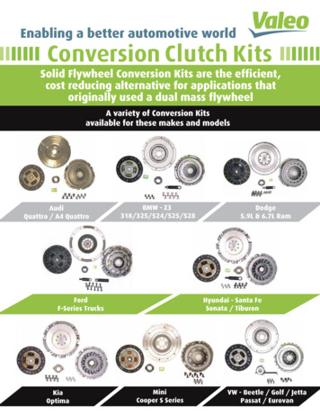
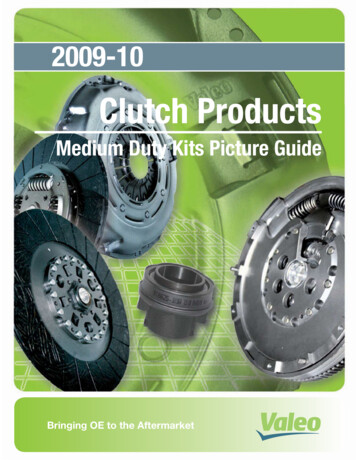
Electrohydraulic Control UnitElectrohydraulic Control UnitThe electrohydraulic control unit is integrated into the mechatronic module. It generates the oil pressure which isrequired to shift the gears and to actuate the clutches.Oil Pressure Generation and ControlThe oil pressure is generated by the hydraulic pump motor. An oil pressure accumulator ensures that sufficientoil pressure is always present at the solenoid valves.Oil PressureAccumulatorElectrohydraulic Control UnitHydraulic PumpTo Clutch K1To Clutch K2Valve 3 in Gear TrainHalf 1 N435Clutch Valve K1N438 Sub-Transmission2 Valve 2Gear Selector Valve 6/RN440 Sub-Transmission2 valve 4Gear Train HalfPressure regulatorN434 Sub-Transmission1 Valve 2Gear Selector Valve 5/7Gear Selector ValveN439 Sub-Transmission2 Valve 3Clutch Valve K2N436 Sub-Transmission1 Valve 4Gear Train HalfPressure RegulatorN437 Sub-Transmission2 Valve 1Gear Selector Valve 2/4N433 Sub-Transmission1 Valve 1Gear Selector Valve 1/3S390 043Motor forHydraulic Pump V40132
Oil Circuit - Hydraulic SystemOil CircuitThe double clutch transmission operates with two independent oil circuits using two different oils: Oil circuit for mechanical transmission Oil circuit for mechatronic moduleEach oil circuit contains a specific oil.Mechatronic ModuleOil Circuit for Mechanical TransmissionS390 080Oil Circuit - Mechanical TransmissionOil Circuit - Mechatronic ModuleThe oil supply to the shafts and gears of themechanical transmission is the same as in a normalmanual transmission.The oil supply for the mechatronic unit is separatefrom the oil circuit for the mechanical transmission.The oil volume in the mechanical transmissionis 1.7 L.An oil pump delivers pressurized oil so that thehydraulic mechatronic unit components can function.The oil volume in the mechatronic unit is 1.1 L.For the volumes and capacities, always refer to the service information33
Oil Circuit - Hydraulic SystemOil Circuit Flow ChartBasic Oil CircuitPressure Limiting ValveFilterV401 Hydraulic Pump MotorPressure AccumulatorHydraulic Pressure SenderNon-Return ValveHydraulic PumpS390 09834
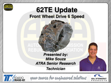
Oil Circuit - Hydraulic SystemHydraulic PumpThe hydraulic pump unit is located in the mechatronicHydraulic Pumpmodule. It consists of a hydraulic pump and anelectric motor.The motor for the hydraulic pump is a brushlessDC motor. It is actuated by the mechatronic unit’selectronic control unit depending on pressurerequirements. It drives the hydraulic pump through acoupling.S390 043V401 HydraulicPump MotorThe hydraulic pump operates just like a gear pump.It pulls in hydraulic oil and pumps it into the oil circuitat a pressure of approximately 70 bar.Intake SideThe hydraulic oil is pumped from the intake side tothe pressure side between the walls of the pumphousing and the tooth gaps.HousingPressure SideDriving GearS390 07135
Oil Circuit - Hydraulic SystemV401 Hydraulic Pump MotorDesignLike conventional, smaller DC electric motors, thebrushless DC motor has a stator and a rotor. Whilethe stator consists of permanent magnets and therotor of electromagnets in the conventional, smallerelectric motor, the opposite is true in the case of thebrushless DC motor.Rotor with PermanentMagnetsTorque to theHydraulic pumpElectrical ConnectionThe rotor consists of six permanent magnet pairs.The stator has six electromagnet pairs.Electromagnet Pole PairsS390 085How It WorksStatorIn the conventional DC motor, commutation (currentdirection change-over) takes place via ring contacts.Commutation in the brushless DC motor is carriedout by the mechatronic unit's electronic control unitand is contact-free.The stator coils are actuated to that a rotatingmagnetic field occurs in the stator coils. The rotorfollows this magnetic field and is rotated.StatorThanks to contact-free commutation, the DC motorruns entirely wear-free, with the exception of bearingwear.RotorS390 08936
Oil Circuit - Hydraulic SystemElectrical ActuationThe mechatronic unit controls switching between the individual poles to ensure smooth rotational movement.This changes the magnetic field. As a result, the rotor is rotated.The schematic shows the design of the circuit usingthe example of a wound coil.3rd Phase2nd PhaseSupply Voltage1st PhaseMechatronic UnitControl UnitWound CoilS390 086Legend1st phase – positively switched2nd phase – negatively switched3rd phase - open37
Oil Circuit - Hydraulic SystemG270 Hydraulic PressureSensor and Pressure LimitingValvePressure Limiting ValveHydraulic Pressure SenderThe hydraulic pump pumps the hydraulic oil throughthe filter towards the pressure limiting valve, thepressure accumulator and the hydraulic pressuresender.When the hydraulic oil pressure at the pressurelimiting valve and the hydraulic pressure senderreaches approximately 70 bar, the control unit turnsthe electric motor and hydraulic pump off. The bypassensures that the system functions if the filter channelis clogged.S390 100Pressure AccumulatorPressure AccumulatorThe pressure accumulator is designed as a gaspressure accumulator.It provides the hydraulic system with oil pressurewhen the hydraulic pump is turned off. Its storagevolume is 0.2 litres.S390 09638
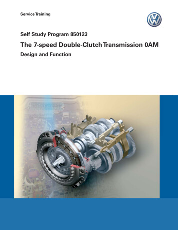
Oil Circuit - Hydraulic SystemOil Circuit Flow ChartWorking PressureReturnControlled Working PressureKS Clutch Safety ValveKSClutch Actuator K1Gear Selector 1 - 3LegendKSGear Selector 6 - RGear Selector 4 - 2S390 048Gear Selector 5 - 7N433 Valve 1 in Gear Train Half 1N434 Valve 2 in Gear Train Half 1N435 Valve 3 in Gear Train Half 1N436 Valve 4 in Gear Train Half 1Clutch Actuator K2N437 Valve 1 in Gear Train Half 2N438 Valve 2 in Gear Train Half 2N439 Valve 3 in Gear Train Half 2N440 Valve 4 in Gear Train Half 2The clutch safety valves enable the clutches to be drained and therefore opened in the event of a fault.39
Oil Circuit - Hydraulic SystemSolenoid ValvesGear Train Half Pressure Control Solenoid ValvesGear Train Half 2Pressure ControlValveThe gear train half pressure control solenoid valvescontrol the oil pressure for gear train halves 1 and 2.If a fault is detected in a gear train half, the pressurecontrol solenoid valve can shut off the correspondinggear train half.S390 101Gear Selector Solenoid ValvesThe gear selector solenoid valves control the volumeof oil to the gear selectors. Each gear selector shiftstwo gears. If no gear is engaged, the gear selectorsare held in the neutral position via oil pressure.Gear Train Half 1Pressure ControlValveGears 5/7Gears 6/RIn selector lever position "P" and when the ignition isswitched off, 1st gear and reverse gear are engaged.Gears 2/4S390 102Clutch Actuator Solenoid ValvesThe clutch actuator solenoid valves control thevolume of oil to the clutch actuators. The clutchactuators actuate clutches K1 and K2.Gears 1/3K1When not supplied with current, the solenoid valvesa
Double Clutch and Torque Curve The double clutch is located in the bell housing. It consists of two conventional clutches, which combined form a double clutch. During the remainder of this SSP, the clutches are referred to as K1 and K2. Clutch K1 transfers the torque to drive shaft 1 via spl