Transcription
Super stairs lightingcontrollerSTX-2195The STX-2195 controller is used for dynamic lighting control of the stairs. Its operation isbased on an advanced animation of switchingon the backlight of successive steps depending on the direction of movement: climbingor descending.The controller has a built-in clear OLEDtext display, with which you can set all theparameters of the controller.The most important features of the STX-2195 controller: — built-in display for setting parameters and checking the operation of the controller— exits for 25 steps and 2 handrails,— 7 preset programs and 4 user’s own programs— all programs can be changed and modified by the user— there are 43 different animations from which you can build your own programs— built-in twilight sensor,— mezzanine service with additional access to the stairs— triggering by buttons and motion sensors,— remote control via phone app (Android only!)The controller has 7 different stair lighting animation programs for both directions. Additionally,the user can define his own 4 programs or change the operation of factory programs. There are43 different basic animations available, from which you can create any programs for switching thestairs on and off.Setting parameters, changing programs and other activities related to the operation of the controllercan be corrected and changed using the built-in screen on which relevant information is displayed.This facilitates the operation of the controller.You can choose one of the predefined programs permanently or set options so that the selectedprograms change cyclically or randomly.The controller has five inputs: three to operate the sensors: bottom, top and platform, and twoadditional: one to turn on the light permanently and one to change programs. An additional input allowsyou to connect an external light sensor (included) to block the animation of the stairs in bright lighting.Depending on the parameter settings of the controller, the lighting of the stairs may go out to zeroor to a certain minimum value that allows you to lightly illuminate the stairs for their presentation,or to make it easier to move around them in the dark - without turning on the full lighting (especiallyimportant for children!).1www.stairslight.com
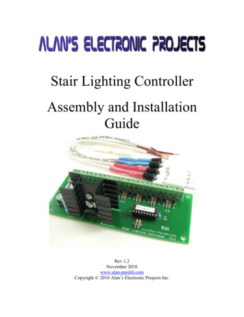
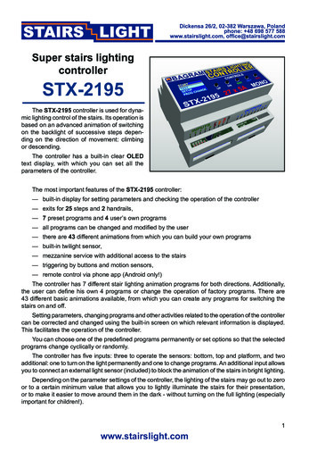
It is adapted to control MONO LED strips placed in the steps of the stairs. The controller cansmoothly brighten the lighting of each step, which gives an effect pleasing to the eye.The lighting can be started in the simplest version by pressing a push button on the wall connected directly to the controller or by using (additionally) a sensor (infrared, movement, pressure, etc.)detecting the moment when a person enters the stairs.The controller can operate up to a maximum of 25 steps. It can also control the illumination ofthe stair railing - one or two handrails. If there are no illuminated handrails, the device can control,for example, ceiling lighting (12V). The controller also supports stairs with a landing and an entranceto the mezzanine. An additional sensor or button is then required.All driver parameters can be set by the user. You can set the number of steps in the range from5 to 25. You can also set the illumination of one or two handrails. You can also change other parameters yourself. These are, among others: selection and change of light animation programs andtheir pace, switching on or off the backlight of stairs in the dark. If motion sensors are used, you canset the dead time of entering after receiving a signal from the sensor or no response to one or bothsensors until the animation of the stairs is finished, which prevents the lighting from being turned onagain when descending the stairs. You can also set a long start-up time of the controller so that itdoes not respond to transient states of the sensors after turning on the power. You can also restorethe factory settings at any time.The device can be controlled remotely using an Android smartphone using a dedicated application - downloadable from the store’s website.DisplayDisplay and buttonsDescription of the buttons on the housing:UPDNENTRETESC– up button– button down– option selection button– back button– exit button from the menu2www.stairslight.com
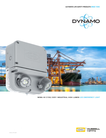
Technical specificationsThe maximum number of illuminated stairs - 25Number of illuminated handrails - 2Supply voltage - 12VDimensions: length - 11 cm, width - 9 cm, height - 7 cmT-35 rail mounting - 6 modules wide.Load capacity of one output - up to 5AStart-up - by shorting the input to ground (to the minus of the 12V power supply).DisplayThe controller is equipped with a small display and 5 control buttons.With their help, you can conveniently set all the parameters of the controler,the way it works, as well as test the LED installation or even turn on theprogram demonstrating the capabilities of the device.The controler is shipped with the English language version set. However, itmay happen that you accidentally switch the controller to the Polish languageversion. We will describe how to restore the English version.If the display is blank, press the UP or DN button and in the START menuand press the UP and DN buttons to find the JEZYK (language) item asshown in the figure.Now press the ENT button to select the preset item. The JEZYK menu appears. The current language is marked with a dot to the right. Here, highlightEnglish and press ENT. The menu language will change to English.After this operation, the START menu will appear in English with LANGUAGEselected.After pressing the ESC button, you can always return to the main STARTmenu.Menu maneuvering is simple but requires attention. Use the UP and DNbuttons to move the highlight up or down to the desired position. Use theENT button to select or activate a given option. The RET button is used toreturn or exit without selecting / enabling the option. You can always returnto the START menu with the ESC button, i.e. restart the program (not to beconfused with the reset of settings!).3www.stairslight.com
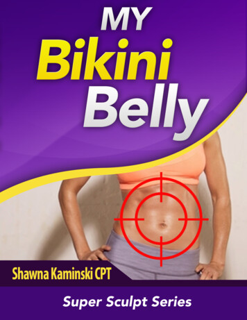
LED lightingSTX-2195 can control the backlight realized with LED strips or 12V lamps (but not 230V!). TheLED strips are usually mounted under the step and the lamps on the side of the step. The connectionof lighting elements is shown in the following figures.LED stripsA popular way to illuminate the stairs is to use LED strips. In the case of the STX-2195 controller, one-color (MONO) tapes should be used. The color doesn’t matter. The STX-1796 controller isdesigned to control colored (RGB) tapes. The standard supply voltage for LED strips is 12V. You canalso connect LED strips powered with 24V voltage to the controller, but due to the electronic systemof the controller, this voltage should not be exceeded.LED strips are most often placed under the steps. Points ( ) should be connected together andwith a single wire with a cross-section of 1.5 mm2 connected to the controller. On the other hand, thepoints (-) of the LED strips should be led to the controller with separate wires with a cross-section of0.5 mm2, as shown in the figure below.Electrical installation of stairs — LED stripsYou can also lead to the controller separately, one pair of wires with a cross-section of 0.5 mm2from each LED strip. Both solutions are of equal importance.4www.stairslight.com
After assembling the strips and bringing the cables to the place where the controller is installed(e.g. switchgear), check the operation of the LED strips. The tapes should be connected reliablyand permanently. Each section of the tape should be checked for a possible short circuit in the wiresor in the tape itself. It is not allowed to connect to the driver tapes, the operation of which hasnot been thoroughly tested before!The installation should be carried out very carefully and permanently in order to avoid looseningthe wires or short circuits between them in the future. The wires should be soldered to the LEDstrips. We do not recommend using special sockets and plugs, because after some time, due to themovements of the stairs, they become loose and lose contact.Electrical installation should take into account possible easy replacement of the section of thetape, which will be damaged for various reasons, or individual diodes in it will go out. The way thecontroller works, the so-called PWM, maintains LEDs and extends their service life.When designing the connections between the controller and the LED points, please take intoaccount the currents flowing in the circuit and select the cross-section of the electric wires accordingly. The plus cable for the 12V power supply to LED strips or lamps should have a much largercross-section than the cables between the controller and individual strips.The diagram below shows the connection of the controller to a stair consisting of 18 steps andtwo handrails. Connect the output No. 1 to the first, lower step, output No. 2 to the second (higher)step, etc. Output 26, looking from the bottom of the stairs, is connected to the left handrail (goingdown), and output 27 to the right handrail (going up) . Observe the rule that all points ( ) of the LEDstrips should be connected with each other and with the PLUS of power supply, Points (-) should beconnected to the appropriate outputs of the controller.5www.stairslight.com
LED spotsAnother way to illuminate the stairs is to place a small LED lamp (spot) on the wall, above eachstep. The lamps must be designed to be supplied with 12V and work in the same mode as the LEDstrips (configuration type: LED resistor). You cannot use lamps with their own drivers - they will notwork properly and most of the light animations will not be visible. If possible, lamps should be placedabove each step - this will ensure a smooth animation effect. If there is a landing - you can add 1-3lights to increase the effect and treat them as the next stairs between the steps.The connection of the lamps is identical to that of the LED strips and should be made accordingto the diagrams on the previous pages.InstallationThe installation of the controller should be carried out by a person with advanced skills in the fieldof electrical engineering, preferably a certified specialist. Connecting the controller must be strictlyperformed with the power off!The controller and LED power supply should be stabilized with appropriate current efficiency depending on the number and length of LED strips or 12V lamps used. Do not use powersupplies 12 from halogen lamps - the controller will be damaged immediately! The controlleris designed for a supply voltage of 12V DC (stabilized voltage). The maximum current for oneoutput is 5A. This value should not be exceeded.Before connecting the controller, check the operation of the LED strips. The tapes should beconnected reliably and permanently. Each section of the tape should be checked for a possible shortcircuit in the wires or in the tape itself.First, the lighting of the stairs should be connected to the controller — LED strips or lamps (spots).At this stage, please do not connect sensors or buttons to the controller inputs. After connecting the12V power supply to the controller, the lighting of the stairs should turn on with minimum brightness- the effect of the so-called stairs illumination. 15 steps will be lit as this amount is factory set.6www.stairslight.com
TestingAfter connecting the LED strips and power supply, the start menuwill appear on the controller display. Note: the display turns off after oneminute of inactivity, but turns on again when any button is pressed. At thisstage, go to the TEST menu, i.e. select the TEST item from the STARTmenu and press ENT.The TEST menu will be shown with several options to choose from. Thefirst three options can be used to check if the LED is installed correctly.ALL ON. — turns on the LED permanently on all outputs of the controller.BLINK ALL — the controller turns on and off all outputs cyclically, whichallows you to check which LEDs are working properly, ONE STEP — lightsup only one step, and using the UP and DN buttons you can change thenumber of the enabled step.Each test option can be exited by pressing the RET or ESC button.All these options allow you to carefully check the operation of the LEDand remove any faults. ATTENTION: all manipulations with LED wires,switching, soldering and correcting the installation should be performed with the controller turned off!Now set the target number of steps and handrails. From the START menu,choose the SETUP item and go to the menu of the same name.STAIRS NO — you choose the number corresponding to the number ofilluminated steps on the stairs;RAILS NO — set one of the three options: 0 — when there are no illuminated handrails, 1 — for one handrail, 2 - for two handrails. In the lattercase, there must be two handrails placed along the entire staircase on bothsides of them. The controller will activate the appropriate railing dependingon the direction of ascending or descending.TO LAND NO — you set the number of stairs from the bottom to the landing,if you have a landing on the stairs with a separate entrance to other rooms.Now you can go back to the TEST menu and select the PROG TEST optionto test the stair light animation programs.A menu will appear with a long list of programs stored in the controller.There are seven preset programs: Bright, Steps, Fall, Lift, Wave, News,and four user changeable programs: Custom 1 to 4.There is a marker next to each program showing the direction of theanimation:— upward direction,— downward direction,— universal animation, the same for both directions.After selecting the appropriate program and pressing ENT, the selectedanimation will be displayed on the stairs. The PROG TEST option allowsyou to check the operation of all programs, which will then facilitate theselection of active programs as well as the change or programming of yourown programs. For own programs, the brightening animation is set at thefactory - it can be changed while programming the animations.7www.stairslight.com
ControlThe controller inputs operate on the principle of shorting to ground. It is enough to connect amechanical button (not a switch) to each of them to start the controller after a short press. One contactof the button should be connected to the controller input, and the other to the ground (minus of the12V power supply). This solution is shown in all figures. Note: Sensors and buttons can be installedsimultaneously in parallel connection as shown in the following diagrams.You can also run the controller with other elements or devices, most often with motion sensors.The motion sensors present on the local market are not suitable for working with the controller formany reasons:— are adapted to control the light and have too long pulse time: from several dozen secondsto several dozen minutes. For the controller, an impulse is needed not longer than approx.5 seconds, preferably approx. 1 second or shorter.— they work more often in the so-called pulse dragging mode - they extend the pulse if thereis a person moving in the room within their range.— voltage dangerous for the controller appears at the output of the sensor: from 230V to 12V or5V. Such sensors must not be connected to the controller under any circumstances!— the only permitted type of sensor output are NO (Normally Open) relay contacts not connectedat any point to the sensor supply voltage!In case the buyer of our product would like to apply their sensor solution, please contact us beforepurchasing it. We are happy to provide any information and help you solve the problem.For our part, we recommend a whole range of our sensors adapted to work with the controllerswe produce.8www.stairslight.com
Motion sensors for 5-12V voltageLow voltage sensors differ in dimensions, capabilities and working principle. We will brieflydiscuss all of them. For detailed information, please refer to the instructions for each type of sensor.Motion Sensor 12V wall mounted with twilight CRN-5480The CRN-5691 is a motion sensor for 12V voltage with wallmounted case for applications as a device that triggers controllerswhen motion of an object is detected. The sensor is cooperatingwith lighting controllers for stairs. The sensor detects objectsemitting infrared (heat) radiation, such as people or animals.The sensor sends a fixed-length pulse (about 5 sec) after motiondetection. The pulse has a negative level and can be connecteddirectly to the controller input. A special feature of the sensor isthe twilight sensor instaled.Miniature motion sensor 12V CRN-5686 with sensitivity adjustmentThe CRN-5686 is a subminiature motion sensor for 5V voltage for applications as a device that triggers controllers whenmotion of an object is detected. The sensor is cooperating withlighting controllers for stairs. The sensor detects objects emittinginfrared (heat) radiation, such as people or animals. The sensorsends a fixed-length pulse (about 5 sec) after motion detection.The pulse has a negative level and can be connected directly tothe controller input.Standard motion sensor 12V CRN-5481The CRN-5481 sensor fits freely into a 60 mm mountingbox. Dimensions: 32x24x18 mm. The sensor has a wide rangeof sensitivity adjustment, as well as a removable large bowl thatcan be accurately outlined to reduce the field of view. It can bepowered from the same voltage (12V) as LEDs.Compact Twilight Motion Sensor 12V CRN-5684A special feature of the CRN-5684 sensor is the twilight sensorinstalled. It blocks the work of the sensor if the light level exceeds the set value. The sensor fits freely into a 60 mm mountingbox. Dimensions: 26x24x18 mm. The sensor has a wide rangeof sensitivity adjustment, as well as a removable large bowl thatcan be accurately outlined to reduce the field of view. It can bepowered from the same voltage (12V) as LEDs. It has a diodesignaling the sensor pulse.9www.stairslight.com
Ultrasonic sensor 12V CRN-5462The CRN-5462 ultrasonic motion detector has a preciselyadjustable field of view range from 1 cm to 250 cm. The field ofview can have a selected depth and distance from the sensor inthe range of 1 cm to 250 cm. Dimensions: 46x20x20 mm. Thesensor fits freely into a 60 mm mounting box. It can be suppliedwith the same voltage as the LED diodes. It has a diode signalingthe sensor pulse.Installation of sensorsEach low voltage sensor can be directly connected to the controller input. It is important that thesensor and the controller itself are connected in the correct way.On the back of the sensor is a connector for connecting wiresleading to the controller. To facilitate assembly, to each sensoris added the connector to soldering wires. You should keep thecorrect order of wires according to the description on the sensorconnector.It is recommended to use colored wires with a possibly smallcross-section, eg a telephone cable harness. Please note thatany mistake in connecting wires, especially power supplies, candamage the sensor or controller. To facilitate assembly, to eachsensor is added the connector to solderingThe sensor’s angle of view can be adjusted by gluing the sensor’s bowl (removed) from the inside with a white insulating tape so that it does not see people passing by. For the ultrasonic sensor,select and set the work zone.The sensors can be mounted in a skirtingboard or bound. It’s best to use the so-called framewith end cap. A hole should be drilled in the cap with the diameter of the sensor bowl or with thediameter of the emitters.Before installing the sensors, their operating time and sensitivity must be set to minimum. In thecase of sensors having a jumper for selecting the mode of operation with or without support (triggering), select the „non-repeatable trigger” position.Two sets of sensors prepared in this way should be installed in a suitable place near to the firstand last stage.The diagram on the next page shows exactly how the whole set is built with the use of 12Vmotion sensors.10www.stairslight.com
Connecting sensors to the controllerAll sensors can be connected to the controller with three wires, preferably the so-called a ropewith a cross-section of 0.5 mm2. The cables should not be longer than 20-30 m. It is recommendedto use cables with colored insulation so as not to confuse them when connecting to the power supplyand the controller.The power supply of the sensors can be connected to 12V, although we recommend connecting the power cord to a special 5V voltage provided by the controller. The sensor OUT output isconnected to the appropriate controller input, and the GND terminal to the power supply minus ofthe entire system (–12V).The diagrams below show the installation details. Note: The diagrams show buttons for manualcontroller release. They are not necessary and can be omitted.Recommended way of connecting 12V motion sensors to the controller.The supply voltage of the sensors is 5V.The CRN-5492 sensor should be powered from the 12V voltage.11www.stairslight.com
An alternative way to connect 12V motion sensors to the controller.The supply voltage for the sensors is 12V.The CRN-5492 sensor should be powered only from the 12V voltage.An alternative way of connecting CRN-5691 motion sensors to the controller.12www.stairslight.com
Connecting three 12V motion sensors to the controller - platform operation.The supply voltage for the sensors is 5V or 12V.The CRN-5492 sensor should be powered only from the 12V voltage.Sensor testingAfter completing and checking the installation supplying the signal from the sensors to the controller, you can start connecting the sensors.Please connect the sensors one at a time, not all at once. First, please connect the lower sensorand check its operation. Enter the stairs with a normal step. If the sensor is not working properly, it isnecessary to make appropriate corrections of its sensitivity and position. You can also limit its field ofview by pasting the white bowl on the inside with white insulating tape or painting it with white paint.If everything works properly, disconnect the sensor temporarily and similarly test the operationof the upper sensor, and then also separately, the sensor for the platform (if needed).Only after checking all the sensors separately, can they be connected together to the controllerand check the operation of the whole again.If there is any doubt about the sensor pulse time, this can be checked with aspecial sensor time test tool. From the TEST menu, select the SENS TIMEoption. Only the detector under test should be connected to the inputs.After the sensor is activated, the display will show the number of the inputto which the sensor is connected and the duration of the pulse. The pulseshould not be longer than 10 seconds. You can exit the sensor time measurement option by pressing the RET or ESC button.13www.stairslight.com
Controller settings for sensorsThe controller has two options for the operation of sensors: You can findthem in the SETUP menu. These are: dead time and sensor lock.DEAD TIME — this is the time counted from the beginning of the animation,during which the controller will not respond to subsequent impulses. Thisprevents the animation from restarting if another impulse comes from thesensor, generated e.g. by a second person entering. It can be set from 1to 30 seconds. It is factory set to 3 seconds.SENSOR LOCK — allows you to block the other sensors for the duration ofthe animation. This option prevents e.g. the second sensor from restartingthe animation when descending the stairs. No Lock is set at the time offactory shipment. Opposite — blocks the opposite sensor for the durationof the animation; Mid and opp — blocks the middle and opposite sensorsfor the duration of the animation; All lock — blocks all sensors, includingthe sensor that triggers the animation.14www.stairslight.com
Light sensorThe controller has a built-in digital light measurement system. The set includes a small probe tomeasure light. If it is connected and properly adjusted, it will be able to disable the operation of thecontroller when the light level is above the set value.NOTE: The sensor connection socket is covered by the factory. Please do not remove thelock without need, do not connect any other devices, your own sensors, do not measure witha meter etc. It may lead to permanent damage of the controller!The diagram below shows the connection of the sensor included in the kit to the controller.Connecting the world sensor to the controller to the controller.Motion sensors and buttons are omitted.The sensor is unipolar and the direction of its connection is not important. Just remember toconnect one of its cables to the POWER MINUS (GND) and the other to the OPT socket. Connectingthe sensor should be performed with disconnected power supply of the unit and the controller. Thelength of the light sensor wires is not critical, but should not exceed 10 m. It should be ensured thatno artificial light falls on the sensor that could interfere with its measurements.Please do not experiment with other light sensors!www.stairslight.com15
In order to adjust the light sensor, the sensor should be installed in the target place so that it detectschanges in the light intensity important for blocking the switching on of the stairs. Setting the parametershould be performed when the lighting has a threshold value, i.e. below the brightness at that moment,the controller is to turn on the animation, and above this brightness — to block it (not to turn on).To set the sensor activation threshold, select SETUP from the START menuand select LIGHT SENS. from this menu.On the next screen: Sensor — means the current brightness at the locationof the sensor; Old lev — previously set value; New lev — new value setby UP and DN buttons. The range of values is 0 to 50. Using the currentbrightness indication, set New lev to the same number or slightly higheror lower than the Sensor indication.For clarification: Setting the value New lev to 50 will make the controller work always, regardlessof the sensor lighting. If New lev is set to 0, the controller will not power on at all. Therefore, the valueof New lew should be set between these extreme numbers, close to the value of 25.The selected value is confirmed by pressing the ENT button. From now on, switching on thecontroller will be blocked if the sensor lighting level is higher than the set value. Also, the backlightof the stairs will be turned off.16www.stairslight.com
Main controller settingsSTART menuThe START menu contains three main items: TEST — a set of options fortesting the controller and previewing the operation of programs; SETUP— options for adjusting the controller settings; PROG CHANGE — itemfor changing the operation of existing programs or designing your ownprograms. You can navigate through the menu by pressing the UP and DNbuttons, and the selection is made by pressing the ENT button.SETUP menuHere you can set and change the main parameters of the controller. Parameters should not be changed without reason. Please think carefully beforechanging any of the parameters. In the event of a controller malfunction,you can always use the RESET option and restore the factory settings.Only options that have not been discussed before will be discussed here.STAIRS NOThe controller is factory set to operate 25 stairs. You almost always needto change this value. The previously selected number of stairs is markedwith a dot. By moving up or down with the UP and DN buttons, set thedesired number of highlighted steps and confirm it with the ENT button.RAILS NOThere are three values to choose from: 0 — no handrails, 1 — one handrail(may be in several sections), 2 — two handrails. In the latter case, thereshould be separate handrails on both sides of the stairs. The controllerwill activate one handrail when going down and the other when going up.TO LAND NOIf the stairs have a landing (mezzanine) with access to other rooms, a thirdsensor can be installed to activate the animation when a person enteringthe stairs from the mezzanine is detected. Here you can set the numberof steps from the bottom to the landing (landing). The controller will thenstart the proper step animation.17www.stairslight.com
LAND PROG.Immediately after setting the number of steps to the landing, the menu forsetting the animation program for the landing will appear. There are threeanimations to choose from: brightening, lighting up and down steps individually, and a wave flowing from the landing in both directions — up and down.BACKLIGHTThe controller can gently illuminate the stairs for their presentation, or foreasier navigation in the dark - without turning on the full lighting (especially important for children!). Set the appropriate value: 0 — no backlight,1 - 20 — backlight level, where 1 means minimum, and 20 — maximumbrightness for the backlight.SEQUENCEThe controller has 7 own and additionally 4 user programs. Here you canset which programs are to be displayed and in what order. There are threeoptions to choose from: In order — selected programs will be displayedsequentially, Random — programs will be displayed randomly, One prg.— only one selected program will be displayed.After selecting the first or second option with the ENT key, a list of programswill be displayed, with active programs marked with a dot. You can scrollup and down through the list, and switch the selected program on or offwith the ENT button. After determining the active programs, the RET buttoncan be used to exit this option. From now on, the selected programs willbe displayed in the way selected at the beginning (In order or Random).When selecting the third option, One prg. — from the list of active programs, select one fixed program with the ENT button. Then only it will bedisplayed by the controler. Changing one program to another is of coursepossible in the above-described manner or by using a button connectedto the PRG input.STAR
The controller can operate up to a maximum of 25 steps. It can also control the illumination of the stair railing - one or two handrails. If there are no illuminated handrails, the device can control, for example, ceiling lighting (12V). The controller also support