Transcription
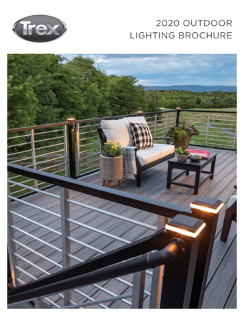
Stair lightingcontrollerSTX-1794STX-1792 controller is used to control stairslighting dynamically. The backlight is switchedon with the subsequent steps, depending onthe motion directions: ascending or descending.The controller has 3 different light animationprograms (for upward direction): WAVE – stairslight up one after another in the direction ofentry, CASCADE – light „jumps” fast from topto bottom, lighting up the steps, ELEVATOR –three lighted steps are slowly „moving” to the top of the staircase. When descending to the bottom,the animation respectively changes direction. You can permanently select one of the programs orset the options to change programs on a regular basis.Depending on the setting parameters of the controller, the light of the stairs can fade out to zeroor to a minimum value (allowing to illuminate the stairs for better presentation, or climb them easilyin the dark — without turning on a full light — especially important for children!). When you pressthe top button, the stairs are lighted from top to bottom and turned off also in the same direction.The controller is adapted to control the MONO LED strips arranged in stair steps or points (spots)LED built into the wall above the steps. LED strip driver can smoothly dimm at each step which givesa nice effect to the eye.In case when another person steps on the stairs, the controller switches on full illumination ofstairs and fade them out smoothly.Lights can be turned on by pressing directly button on the wall, connected to the controller orby the use of additional sensor (infrared, motion, pressure, etc.) to detect when the person stepson the stairs.The controller can support up to 20 steps. It can also control lighting of handrail — in this case thenumber of steps is reduced by the number of handrails (max. 2). If there is no handrail, the controllercan highlight, for example, ceiling lights (12V).All the parameters of the controller can be set by the user. In the original (factory) settings, thecontroller is ready for lighting up 15 steps, without lighting up the railing. It can be set up for a differentnumber of steps, from 5 to 20. It is also possible to light up one or two rails. Other parameters canalso be changed. These include the backlight on or off the stairs in the dark, steps lightening time,the time interval between successive step lightening (it has an impact on the speed of lightening allof the stairs), or the time after which the steps will be faded out. If used motion detectors, “dead”time can be set after receiving a signal from a sensor, or a lack of response to one or both of thesensors until the end of the animation program, to prevent re-integration of lighting while descending the stairs. You can also set a long time to start up the driver does – it will not react to transientsof the sensor while power is on. Possibility of changing options can be locked. At any time, you canalso restore the factory settings.1www.stairslight.com
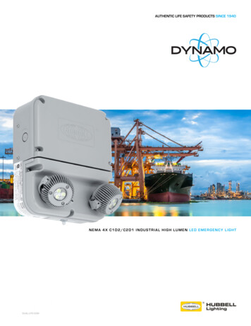
SpecificationsMaximum number of illuminated stairs — 20 (or 18 steps and 2 handrails)Quantity of illuminated handrails — 2Voltage — 12VDimensions: length — 11cm, width — 9cm, height — 7 cmMounting on T-35 rail — the width of 6 modules.Output capacity — up to 5ARunning — by shorting the input to ground (negative power supply)Buttons functions and LED control2www.stairslight.com
InstallationDriver Installation should be done by the person having advanced skills in the field of electricalengineering, preferably a specialist with permission. Connecting the controller must be strictly carriedout with the power off!AC driver and LEDs should be stabilized with adequate current capacity dependent on theamount and length of the used LED strips or 12V LED light. Do not use a power supply (type12) from halogens — the controller will be damaged immediately! The controller is designed fora voltage of 12V DC (stabilized). Maximum current per output is 5A. Do not exceed this value.The first step is to connect the lights (LED strips or spots) to the driver. When you connect the12V power supply, the stairs lightning should turn on with minimum brightness (so-called stairs illumination effect). When you press UPSTAIRS ANIMATION button (indicated by arrow pointing up)on the controller body, the controller should start lighting up the steps one by one. After pressingDOWNSTAIR ANIMATION button (indicated by arrow pointing down), the stairs lightning should godown. If there is no effect or steps are lighting up in a different way, you should check again carefullyhow to connect LED lighting.Then it is recommended to adjust the sensor response to the movement without connecting themto the controller inputs. Be sure to first set the sensor pulse time (TIME) to extreme minimum and itshould not be changed during adjustment, and the sensitivity (range) also at the minimum - but thisparameter can be adjusted. In some sensors, there should be disabled or properly adjusted supportfunction (called triggering). Only after obtaining the proper operation of the sensors, they can beconnected to the controller.After connecting the sensor, if only the first step is flickering, or the entire staircase is lighted,this means that the sensor pulse time exceeds 20 seconds, or is short-circuited. The sensor shouldbe immediately disconnected from the controller and replaced operating properly.Only after obtaining the proper light animation, you can begin to connect the motion sensor. Besure to pre-set the operating time of sensors for extreme minimum and sensitivity (range) also atthe minimum value. With some sensors, there should be disabled or switched triggering function.The last step is time intervals adjustment. The best way is to do it after a few days of using thestairs in order to determine as accurately as possible the necessary changes. We recommend youto not adjust the parameters for no particular reason.For the higher safety, changing parameters is permanently locked (Look: “Adjusting the controller”).3www.stairslight.com
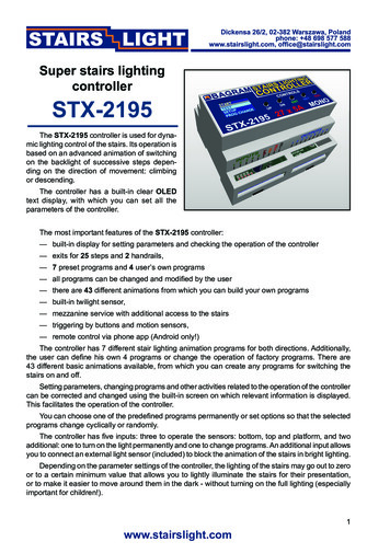
LED LightingSTX-1792 can control the backlight realized by LED strip and 12V LED lights (not 230V!). Stripsare usually mounted under the steps, and the LED lights on the side of the steps. Connections between lighting elements are shown at attached pictures.LED stripsA popular way for the stairs backlight is to use LED strips. In the case of STX-1792 controller,use one-color strips (mono). The color is not important. To control the colored bands (RGB) thereis a dedicated STX-1793 controller. The standard supply voltage is 12V. The controller can also beconnected 24V power, but because of the driver electronics voltage should not be exceeded.Wirediameter1,5 mm2Wirediameter0,5 mm2 Electrical installation of stair treads — LED stripLED strips are usually placed under the steps. Points ( ) should be connected together and bysingle wire of 1.5 mm2 fed to the controller. Points (-) of LED strips should be connected by separatewires of 0.5 mm2 to controller, as shown above.You can also lead one pair of wires for each LED strip to the driver separately. Both solutionsare equivalent.4www.stairslight.com
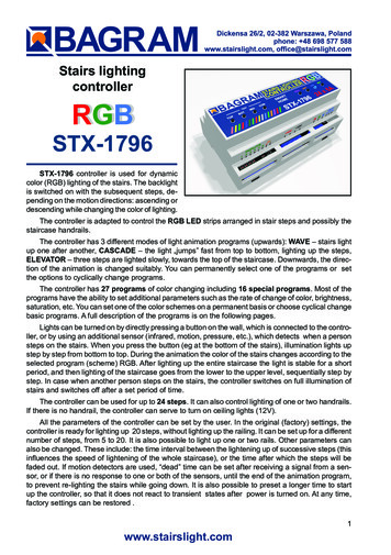
LED strips connected to the controllerThe diagram above shows the connection of the controller to the staircase consisting of 18 stepsand two handrails. Output 1 is connected to the first, lower level, exit 2 to the second (higher), etc.The output 19 is connected, looking from the bottom of the stairs, to the right handrail (running up),and the output 20 to the left handrail (running down) . Please respect the principle that all the points( ) of LED strips should be connected with each other and plus value, points (-) should be connectedto the controller’s outputs.5www.stairslight.com
LED lights (spots)Another way to highlight the stairs is to place on the wall, on each step, a small LED light (spot).Lights must be prepared to supply 12V voltage. We recommend the use of dimmable lights — thenyou will be able to use the backlight of the stairs, and the smooth illumination of each step.12V spots connected to the controllerThe diagram above shows the connection of the controller to the staircase consisting of 18 stepsand two handrails. Output 1 is connected to the first light from the lower level, exit 2 to the second light(from a higher level), etc. The output 18 is connected to the last (18) light. Output 19 is connected,looking from the bottom of the stairs, to the right handrail (running up), and the output 20 to the leftone(running down). Lamps generally have no polarity, so you should just follow the rule that the lightsshould be connected with each other and with the plus value, and the second end of each lamp mustbe connected to the corresponding driver output.If the staircase is smaller and there is no illuminated handrails, for example you can use exit No.20 for ceiling lighting above the stairs (of course, if you have one). However, there must be used LEDelements with 12V power. Do not connect the lighting powered from 230V!6www.stairslight.com
The next picture shows a solution where the exit No. 20 is connected to three 12V LED lightsplaced on the ceiling above the stairs. The driver will be turning it on with the first step and turn off afterabout 2 seconds from the extinction of the last step. Of course, you can use any other light sourcewith the voltage of 12V, depending on the design of the stairs, in place of ceiling lamps.Ceiling lightingWhen designing the connections between the controller and LED points, please include yourcurrent flowing in the circuit and select the appropriate type of wiring. Plus supply line for 12V LEDstrips or LED lights should have a much larger cross-section than the cables between the controllerand the LED strips.Installation must be carried out very carefully and securely to avoid loosening of wires or shortcircuits between them. LED strip wires should be soldered. We do not recommend using specialsockets and plugs, because after a while, due to the movements of the stairs, they are loose andmay lose contact.7www.stairslight.com
ControlDriver inputs are working on a short to ground. Connecting random mechanical button (notswitch) will run the controller after a short press. One end of the button should be connected to thecontroller input, and the other to ground (minus of 12V). All previous diagrams show this solution.You can also run the driver with other elements or devices, including motion sensors. Motionsensors are found in two versions: the 230V voltage and the voltage of 5 or 12V. Do not connect thesensor directly to the input of the driver, because, especially in the case of 230V sensors, it will cause(at best) incorrect working of the controller, and at worst it can be completely damaged.Before mounting the sensors, please set their parameters. The most important is the length ofthe impulse (time of starting the sensor), which should be set to a minimum and should not exceed15 seconds (preferably about 1-5 seconds — this should be checked before purchase). The secondparameter possible to set on the sensor is its sensitivity and range. This parameter should be setexperimentally in order to enable steady and in the right time.In some sensors you can choose from various modes of operation. Please turn off triggeringmode, because in this mode, the sensor provides the impulse continuously when a person is withinits range - and the impulse becomes too long as for the requirements of the controller.Sensors operating at 230V network require the use of transmitters to separate the 230V circuitfrom the controller inputs. LV Sensors will almost certainly need a special adapter matching thesensor signal to requirements of the controller. The following diagrams and descriptions explain howto connect the most common types of sensors. If you need to use a different type of sensor, pleasecontact the manufacturer to agree on how to connect the sensor.Motion sensors for 230V voltageA typical motion sensor (230V) isa standard size module and is connected to the installation box. It hasregulatory elements (time, sensitivity,etc.) and usually three contacts forwires. Two are plugged into a 230Vnetwork, and the third wire is used topower the receiver (the lamp) and ismarked with an appropriate symbol.Before installing the sensor, carefullyread the instructions.Motion sensor for 110-230V - CRN 5491Some motion sensors have a built-in additional twilight sensor. Depending on the sensitivitysettings it can be inactive in strong light. Thus, illumination of the stairs does not turn on during theday. However, this may cause problems - if it rains, the twilight sensor will lighten the stairs. By adjusting the sensitivity, you can try to prevent this. We can recommend our 230V sensor CRN-5491,modified to work with our controller:.The next diagram is one of a typical motion sensor (230V) connected to the controller. Relaysmust be used! Relay coil voltage must be set at 230V, because this voltage is supplied from themotion sensor. Connect input 1 or 2 and (-) of 12V to the contacts of the relay NO (normally open)and CO (common),. We recommend the assembly to be done very carefully. If the connections aremade erroneously, the controller will be damaged.8www.stairslight.com
Installation diagram: 110-230V motion sensors connected to the controllerThe relays used to separate 230V circuit fromthe controller may be of any type. We recommendthe relays to be mounted on T-35 bus, the same asthe controller. Their use helps with the installation.Photo to the left shows our product STP-4811 — aset of two relays in a single-rail case T-35. This setmakes it possible to separate 230 V voltage comingsimultaneously from two motion sensors.Set of two relays STP-48119www.stairslight.com
Installation diagram: motion sensor CRN-5891 connected to the controllerNOTE: Knob “Time” in the sensors must be set to minimum!The picture above shows an example of the assembly of motion sensors operating at 230V. Thereare used two one-connection transmitters with stands for mounting on T-35 bus. Due to the fact thatevery manufacturer of transmitters and sockets uses a different pin configuration, you should alwayscarefully consider how to connect the sensor and the controller to the transmitter so that the driverdoes not connect directly to 230V!Installation of motion sensors in order to work properly isvery difficult, and often impossible. Visualization next to thesensor assembly may help.We recommend to tilt downthe sensor so as to „see” onlya portion of the first step whilecloaking the top of the Fresnellens with opaque material. If themotion sensor does not havebuilt-in light sensor, add at leasta small, steady source of lightover the sensor to light up thefield observed by the sensor.10www.stairslight.com
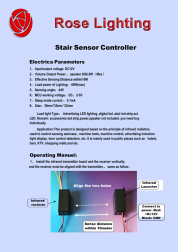
Motion sensors for voltage 12VYou can also use miniature motion sensors operating at low supply voltage such as 12V. We offerthe sensor with the symbol CRN-5481. Voltage of the sensor is identical to the LED supply voltage,which greatly simplifies installation of the entire system.Sensor dimensions: plate: 32.5 x 23.5 mm, thediameter of the bowl: 23mm. The sensor has anadjustable impulse length and sensitivity.The sensor can be connected directly to thecontroller input. It is important that the sensor, theadapter and the driver have been combined in theright way, according to the following pictures anddiagrams.Miniature motion sensorOn the back of the sensor is a connector for connecting wires leading to the controller. To facilitateassembly, to each sensor is added the connector tosoldering wires. You should keep the correct orderof wires according to the description on the sensorconnector.The view of the sensor back sideIt is recommended to use colored cables withthe smallest possible diameter, eg. telephone cablebundles. Please note that any mistake in wiring, especially power can damage the sensor or controller.Sensor socket and plug11www.stairslight.com
Installation diagram: 12V motion sensors connected to the controllerThe diagram below shows exactly how the whole set is made using 12V motion sensors.Before mounting the sensors, please set their time of action and sensitivity to a minimum. In thecase of sensors with a jumper used to select the operating mode with or without triggering, choosethe position “non-repeatable trigger.”These prepared two sets of adapters with sensors should be mounted in appropriate place onthe side of the first and the last step.Setting the motion sensorsThis is one of the most difficult operations — it requires patience and accuracy. First of all, adjustthe sensitivity of the sensor in order to accurate respond to the person entering the stairs. The secondproblem to solve is that the sensor does not respond to the person descending the stairs - that it notre-activate the fading of the stairs. Best thing to do is to cover the sensor hemisphere respectively. Ofcourse, the arrangement of the sensors is also very important — usually they are placed on the rightside of the stairs looking in the direction of movement (when the right-hand ‘traffic’). Some sensorshave additional adjustable parameter - the so-called ‘dead time’. It is a time measured after pulse forwhich the sensor does not respond to the next person entering into the field of its operations. Patientchanging mentioned parameters will adjust quite well the sensors so that their work and lighting thestairs will be rewarding.12www.stairslight.com
Adjusting the controllerSetting the parameters should be performed only when strictly necessary, after carefully readingthe following description. For greater safety, parameters change is already locked. It can be unlockedby the user.To unlock the parameter setting setting mode, press and hold the SETUP button for about 20seconds (it stars lighting up the steps) until the green LED will fade out (at the same time turns offthe lighting of the stairs). Now release the button. After a short while the LED and the first step willflicker. It should again press and hold the SET. When flickering finished, will begin a slow pulses.Release the button after the third pulse. Proper unlock is confirmed by three pulses. Now you canset the desired parameters.Unlock the parameter setting setting modeTo start adjusting parameters press and hold the SETUP button for about 20 seconds (it starslighting up the steps) until the green LED will fade out. Release the button and wait for three pulsessignaling the possibility of setting parameters. Next a few seconds flickering of the LED correspondsto each parameter. You can set or change 13 parameters, and therefore there will be thirteen consecutive flickering of the LED. In order to facilitate counting them, a marker is inserted every five flashesmarker – a two second LED solid light. To select a specific parameter to be changed, you shouldcount each flickering and the at relevant number of the flickering, press the SETUP button. If you donot want to change a parameter, skip the flickering without pressing the button. If at the parametersetting mode the SETUP button is not pressed, none of the parameters will change.Adjusting controller parameters diagramThe principle of setting the parameters is as follows: setting each parameter is indicated by rapidblinking of the green LED. If during this flickering the SETUP button is pressed and held, then, depending on the parameter, you will see from one to dozens of slow LED flashes. Setting the parameteris to release the button with the desired number of flashes or just after the end of flickering. Duringthe flickering, if the SETUP button is not pressed, after a short time of fading out the LED, there willappear flickering of the next parameter and so on until the end of setting mode. If desired flickering isomitted, then the corresponding parameter is not changed. This allows you to set, for example, onlyone parameter, except of all the others. Notice: if the SETUP button is pressed during the flickeringand released immediately after it, but before the first impulse, the value of the parameter will be setto the factory setting.13www.stairslight.com
Setting single parameterAfter setting the selected parameter, the controller immediately returns to a stand-by state, waitingfor a signal from pulse sensors or push buttons. There are no flickers for other parameters. To setanother parameter, use of the SET button again.Note: After 10 startups animation access to the parameter setting will be locked. You canunlock it again by following the instructions at the beginning of the chapter.Description of parametersFlickering 1 – Count of stairs.The controller is factory-set for 15 steps. This can be changed with this parameter. The range isfrom 5 to 23 steps. To change the number of steps, press and hold the SET button during thefirst flickering. You should release the button after the right number of flicks. Eg., to set 18 steps,release the button after 18th flick.Flickering 2 – Count of rails.The controller is factory-disabled for lighting the railing. You can turn on one or two rails. Note:two rails should be set only if in the entire staircase there are handrails on both sides. In othercases, such as one handrail divided into two sections, set the operation to one handrail! Releasingthe button after the first slow pulse sets the lighting for one rail, and letting go after the secondpulse – sets the lighting for two rails. Releasing the button after the end of flickering and beforethe first pulse switches off the backlight railing.Flickering 3 – Staircase backlight.Steps illumination is used to gently brighten the dark steps so as to be easily visible, which makesgood impression. There is no possibility of adjusting the backlight brightness. The backlight doesnot work with lamps having no dimming function (dimmable) and should then be turned off. Forthis parameter (backlight on), releasing the button just after the flickering turns off the backlight,and releasing after the first impulse - enables the backlight.14www.stairslight.com
Flickering 4 – Animation type.The controller has 3 different light animation programs (for upward direction): WAVE – stairslight up one after another in the direction of entry, CASCADE – light „jumps” fast from top tobottom, lighting up the steps, ELEVATOR – three lighted steps are slowly „moving” to the top ofthe staircase. When descending to the bottom, the animation respectively changes direction. Inthe factory, cycle animation function is set: first WAVE, then CASCADE and finally ELEVATOR,and then the sequence is repeated. Releasing the button after the first pulse turns the program1 (Wave), the second pulse will turn on program 2 (Cascade), and releasing the button after thethird pulse switch permanently program No. 3 (Elevator). To turn back cycle animation function,the button should be let go immediately after the end of the flickering.Flickering 5 – Lightening of the steps.You can set the time of slow lightening of the steps. This gives a pleasing effect, rather thana sharp light at full power. The factory setting is 10, which corresponds to 0.5 second time ofsingle step illumination (a total of 10 seconds for 20 steps). Releasing the button after the endof the flickering sets the time to the default value (approx. 0.5 sec. – 10 units). However, if thebutton is held on, you can set a different, shorter or longer period of time illuminating a singlestep. Number of flashes is proportional to the time of illumination. Just hold the button for theappropriate number of flashes (default setting of 10).Marker – Fixed light – 2 sec.Flickering 6 – Time interval between lighting following steps.Releasing the button after the end of the flickering sets the time to the minimum so that the speedof the staircase lighting depends on the time of steps illumination. However, if the illumination time(parameter 4) is set to a low value or zero (eg lamp lights), set the value of the experimental timeinterval so that the steps will light up at the right speed. Number of flashes is proportional to thetime interval and is approximately 0.5 seconds per unit (pulse). This parameter is factory-set to0 (minimum value), which makes the next step is lightened immediately after the previous one.Flickering 7 – Time between illuminating and fading out the staircase.It is a time in which, after switching steps such as one by one, they light up continuously at alllevels, before the start of their fading out. Factory value is set to 10 seconds, which is equal to10 pulses (1 pulse 1 second).Flickering 8 – Time of illumination for the other person.If the next person enters the staircase, illumination of all steps go on. It is re-measured at eachentry of the new person, and therefore light will turn off after a set time measured from the entry oflast person. This time is pre-set to 20 seconds, which equates to 20 pulses (1 pulse 1 second).15www.stairslight.com
Flickering 9 – Controller blockade time.If the sensor detects when a person sends more than one pulse for example, by the movementof other people on the stairs, the driver can react by turning the lights all over the stairs, just likeduring the entrance of another person. To avoid this, you can set the so-called blockade timecounted from the end of the first pulse, during which the driver will not respond to further impulses.Blockade time is pre-set for 2 seconds, which corresponds to 2 pulses (1 pulse 1 second).Flickering 10 – Sensors lock.Important parameter when installing motion sensors. In some cases, motion sensors can not beplaced in an ideal direction, and it happens that when a person starts going down the stairs, andturn all the lights on as if at the stairs came next person. This can be prevented by blocking thesensors in two ways. When you release the button after the first impulse, the opposite the sensor to the sensor that started the animation is blocked. When released after the second pulse,both sensors are blocked. Lock lasts for the duration of the animation to the end of lighting timeof the stairs or turning on the backlight. From that point on the two sensors are again active andanimation can be run in either directions. You can disable the lock by releasing the button immediately after the end of flickering. As you get the controller from the factory, the lock is turned off.Marker – Fixed light – 2 sec.Flickering 11 – Fade out animation.If the other person comes up the staircase, all the lights light up. It can be turned off by a smooth,slow fade or animation of the steps. Releasing the button immediately after the flickering setsthe first option, and releasing after one impulse - the second one.Flickering 12 – Controller delayed start.Some motion sensors, after power on, transmit a long, often tens of seconds, pulse. It can causean incorrect operation of the controller (eg the inclusion of constant light). In this case, you canset a controller delayed start — about 1 minute. At that time, after powering of the whole system,the driver does not respond to the buttons or sensors. This is indicated by the blinking of all steps.Normally, the delayed start function is on. Releasing the button immediately after flickering turnsdelayed start off, and after one impulse – turns it on.Flickering 13 – Changing parameters lock and controller reset.You can reset the controller, or restore it to factory settings (for example, after wrong setting theparameters) by pressing and holding the SETUP button during the thirteen flickering and releasingit immediately after the fifth pulse. A successful reset is confirmed by five slow flashes of the LED.To turn the light of the stairs on the permanently, press and hold for 20 seconds the UP button(ignition of lighting up the steps) until the lights go out at all steps. Releasing the button will lightup the staircase. To turn off the permanent light, press the UP button and hold it for more than 20seconds. The driver then goes to normal functioning.16www.stairslight.com
Stair lighting controller STX-1794. 2 www.stairslight.com Specifications Maximum number of illuminated stairs — 20 (or 18 steps and 2 handrails) Quantity of illuminated handrails — 2 Voltage —