Transcription
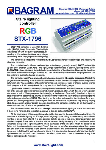
Stairs lightingcontrollerRGBSTX-1796STX-1796 controller is used for dynamiccolor (RGB) lighting of the stairs. The backlightis switched on with the subsequent steps, depending on the motion directions: ascending ordescending while changing the color of lighting.The controller is adapted to control the RGB LED strips arranged in stair steps and possibly thestaircase handrails.The controller has 3 different modes of light animation programs (upwards): WAVE – stairs lightup one after another, CASCADE – the light „jumps” fast from top to bottom, lighting up the steps,ELEVATOR – three steps are lighted slowly, towards the top of the staircase. Downwards, the direction of the animation is changed suitably. You can permanently select one of the programs or setthe options to cyclically change programs.The controller has 27 programs of color changing including 16 special programs. Most of theprograms have the ability to set additional parameters such as the rate of change of color, brightness,saturation, etc. You can set one of the color schemes on a permanent basis or choose cyclical changebasic programs. A full description of the programs is on the following pages.Lights can be turned on by directly pressing a button on the wall, which is connected to the controller, or by using an additional sensor (infrared, motion, pressure, etc.), which detects when a personsteps on the stairs. When you press the button (eg at the bottom of the stairs), illumination lights upstep by step from bottom to top. During the animation the color of the stairs changes according to theselected program (scheme) RGB. After lighting up the entire staircase the light is stable for a shortperiod, and then lighting of the staircase goes from the lower to the upper level, sequentially step bystep. In case when another person steps on the stairs, the controller switches on full illumination ofstairs and switches off after a set period of time.The controller can be used for up to 24 steps. It can also control lighting of one or two handrails.If there is no handrail, the controller can serve to turn on ceiling lights (12V).All the parameters of the controller can be set by the user. In the original (factory) settings, thecontroller is ready for lighting up 20 steps, without lighting up the railing. It can be set up for a differentnumber of steps, from 5 to 20. It is also possible to light up one or two rails. Other parameters canalso be changed. These include: the time interval between the lightening up of successive steps (thisinfluences the speed of lightening of the whole staircase), or the time after which the steps will befaded out. If motion detectors are used, “dead” time can be set after receiving a signal from a sensor, or if there is no response to one or both of the sensors, until the end of the animation program,to prevent re-lighting the stairs while going down. It is also possible to preset a longer time to startup the controller, so that it does not react to transient states after power is turned on. At any time,factory settings can be restored .1www.stairslight.com
SpecificationsMaximum number of illuminated stairs — 20Quantity of illuminated handrails — 2Voltage — 12VDimensions: length — 14cm (5,5’’), width — 9cm (3,5’’), height — 7 cm (2,75’’)Mounting on T-35 rail — the width of 8 modules.Output capacity — up to 5ARunning — by shorting the input to ground (negative power supply)Functions buttons and LED controlDescription of buttons on the body:TOP - button starts the animation towards the topBOT - button starts the animation towards the bottomCON - continuous lightPRG - button to change RGB programsOPT - button for changing options of RGB programsLED - LED indicatorSET - setup buttonDescription of controller inputs:1 — lower sensor,2 — upper sensor,3 — middle sensor serving the mezzanine with stairs access,4 — button for lighting the stairs permanently,5 — button for changing RGB programs,26 — button to change RGB program options.www.stairslight.com
List programs RGB colorIn RGB controller are four colour palletes used:Primary. A fixed selection of saturated primary colours.Vibrant. A stunning range of saturated colours.Bright. A range of bright saturated and pastel shades.Full Spectrum. Every colour that can be achieved from black to white.The standard programs:1.2.3.4.5.6.7.8.9.10.11.12.13.14.Morph and hold with vibrant colours. (Hold delay adjustable in 3 second increments)Morph and hold with bright colours. (Hold delay adjustable)Morph and hold with full spectrum colours. (Hold delay adjustable)Red marker to help you find your way through the programs.Sweep continually between vibrant colours.Sweep continually between bright colours.Sweep continually between full spectrum colours.Green marker.Indie dim with each colour „rambling” independently.Indie dim pastels (all colours 25% min).Blue marker.Rainbow. Can be stopped and started on any colour using option button.Rainbow continuous. (Speed adjustable)Black marker.FX programsRoutines below can only be accessed when unit is in FX mode. To lock and unlock FX mode,hold both PRG and OPT buttons in for about 15 seconds until the output changes from blue to eitherred (locked out) or green 28.29.30.31.32.Colour burst with vibrant colours. (Speed adjustable)Colour burst with bright colours. (Speed adjustable)Colour burst with full spectrum colours. (Speed adjustable)Cyan marker.Colour plasma lightning. (Speed adjustable)White plasma lightning. (Speed adjustable)Colour strobe. (Speed adjustable)Windswept flame effect. (3 independent.) (Speed adjustable)Subtle flame effect. (3 independent.) (Speed adjustable)Rainbow trail. Fast cycle of primary colours to create a colourful trailing effect on fast moving reflectiveobjects or water droplets. The colours cycle so quickly that the output appears to be static white.(Speed adjustable.)Jewel fountain. Similar to rainbow trail but with random vibrant colours. (Speed adjustable)X-Fader. A standard speed adjustable cross fading effect between the red and blue channels.Peppers Ghost. An automated cross fade with hold delay adjustable in 16 3-second increments.Juddermeister. A wild psychedelic effect which alternates rapidly between pairs of random colours.Hazard. Specifically designed for LED hazard warning lights. This effect strobes alternately betweenthe red and blue channel with 8 speed options in one style and 8 in another style.Random fixed full colour. (Reselectable with option button)Random fixed vibrant colour. (Reselectable with option button)White marker.If both program (PRG) and option (OPT) buttons are pressed together briefly the unit will revertto program 1. After any buttons have been pressed the changes will be stored to non volatile memoryand the unit will power up in that mode until further changes are made.3www.stairslight.com
InstallationThe controller should be installed by someone with skills in the field of electrical engineering,preferably a certified specialist. The controller must be installed with the power off!Power supply for controller and LEDs should be stabilized with an adequate current capacitydepending on the amount and length of the used LED strips or 12V LED light. Do not use a powersupply (type 12) for halogens — the controller will be damaged immediately! The controller is designedfor a voltage of 12 V DC (stabilized). Maximum current per output is 5 A. Do not exceed this value.The first step is to connect the lights (LED strips or spots) to the controller. When you connectthe 12V power supply, the stairs lighting should turn on with minimum brightness (so-called stairsillumination effect). When the TOP button on the controller body is pressed, the lighting up of the stepsone by one should begin. If this does not happen, the way the LED lighting is connected should bechecked carefully. Similarly, the animation after the button BOT is pressed should be checked – inthis case , the stairs lighting should take place downwards.It is recommended to adjust the sensor response to movements without connecting them to theinputs of the controller. The sensor pulse time (TIME) must first be set to extreme minimum and itshould not be changed during adjustment. The sensitivity (range) also should be set at the minimum- but this parameter can be adjusted. In some sensors, the support function should be disabled orproperly adjusted ( triggered). Only after the proper operation is obtained of the sensors, they canbe connected to the controller.Only after obtaining the proper light animation, you can begin to connect the motion sensor.The last step is time intervals adjustment. The best way is to do it after a few days of using thestairs in order to determine as accurately as possible the necessary changes. We recommend youdo not adjust the parameters without a specific reason. For greater safety, changing the parametersare blocked by the factory (see the chapter on adjusting the controller)4www.stairslight.com
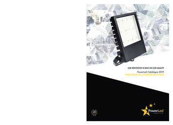
LED LightingSTX-1796 can control the backlight done by LED strips and 12V LED lights (not 230V!). Stripsare usually mounted under the steps. Connections between lighting elements are shown on thefollowing illustrations.Diagram: LED RGB strip connected to the controllerNOTE: Arrangement of points R, G i B on the stripmay vary from shown above!The diagram above shows the connection of the controller to the staircase consisting of 22 stepsand two handrails. Output 1 is connected to the plus ( ) RGB strip from the first, the bottom stepof the stairs, output 2 to the plus ( ) RGB another (higher) step of the stairs, etc. The output 22 isconnected to the plus ( ) RGB strip at last step of the stairs. The output 23 is connected, lookingfrom the bottom of the stairs, to the right handrail (running up), and the output 24 to the left handrail(running down) . Points R, G and B LED strip should be connected properly to each other, ie, all thepoints of R together, all the points of G together and all points B together. Then just set up collectionpoints should be connected to the respective outputs RGB controller.If the staircase is smaller and there is no illuminated handrails, for example you can use exit No.24 for ceiling lighting above the stairs (of course, if you have one). However, there must be used LEDelements with 12V power. Do not connect the lighting powered from 230V!5www.stairslight.com
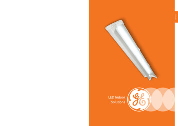
The next picture shows a solution where the exit No. 20 is connected to three 12V LED lightsplaced on the ceiling above the stairs. The driver will be turning it on with the first step and turn off afterabout 2 seconds from the extinction of the last step. Of course, you can use any other light sourcewith the voltage of 12V, depending on the design of the stairs, in place of ceiling lamps.Diagram: Ceiling lightingWhen designing the connections between the controller and LED points, please include yourcurrent flowing in the circuit and select the appropriate type of wiring. Plus supply line for 12V LEDstrips or LED lights should have a much larger cross-section than the cables between the controllerand the LED strips.ATTENTION! You cannot connect the AC to 5V plus ( ) and minus (-) outputs. These contacts are used for low-voltage power sensors.Installation must be carried out very carefully and securely to avoid loosening of wires or shortcircuits between them. LED strip wires should be soldered. We do not recommend using specialsockets and plugs, because after a while, due to the movements of the stairs, they are loose andmay lose contact.6www.stairslight.com
ControlController inputs function on a short to ground basis. Any mechanical button (not a switch) willactivate the controller after a short press. One end of the button should be connected to the controllerinput, and the other should be grounded ((-) of 12V). All the above diagrams show this solution.You can also run the controller with other elements or devices, including motion sensors. Motionsensors can be found in two versions: a voltage of 230V voltage and a voltage of 5 or 12V. Do notconnect the sensor directly to the input of the controller, because, especially in the case of 230Vsensors, it will cause (at best) incorrect performance of the controller, and at worst the controller canbe completely damaged.Before mounting the sensors, set their parameters. The most important is the length of theimpulse (the time for the sensor to start), which should be set to a minimum and should not exceed15 seconds (preferable time about 1-5 seconds — this should be checked before purchase). Thesecond parameter which can be set on the sensor is the sensitivity and range of the sensor. Thisparameter should be set experimentally in order to enable a steady connection at the proper time.In some sensors you can choose between various modes of operation. The triggering mode shouldbe turned off, because in this mode the sensor provides the impulse continuously when someone iswithin its range - and the impulse becomes too long in respect to the requirements of the controller.Sensors operating at 230V network require the use of relays to separate the 230V circuit fromthe controller inputs. Low voltage sensors will almost certainly need a special adapter, matching thesensor signal to requirements of the controller. The following diagrams and descriptions explain howto connect the most common types of sensors. If you need to use a different type of sensor, pleasecontact the manufacturer to establish how to connect the sensor.We recommend that buttons (such as door bell ones) are installed on the top and bottom of thestairs, besides motion sensors,.Motion sensors with a voltage of 230 VThe relays used to separate230V circuit from the controller mayA typical motion sensor (230V) isa standard size module and is connected to the installation box. It hasregulatory elements (time, sensitivity,etc.) and usually three contacts forwires. Two are plugged into a 230Vnetwork, and the third wire is used topower the receiver (the lamp) and ismarked with an appropriate symbol.Before installing the sensor, carefullyread the instructions.Motion sensor for 110-230V - CRN 5491Some motion sensors have a built-in additional twilight sensor. Depending on the sensitivitysettings it can be inactive in strong light. Thus, illumination of the stairs does not turn on during theday. However, this may cause problems - if it rains, the twilight sensor will lighten the stairs. By adjusting the sensitivity, you can try to prevent this. We can recommend our 230V sensor CRN-5491,modified to work with our controller:The next diagram is one of a typical motion sensor (230V) connected to the controller. Relaysmust be used! Relay coil voltage must be set at 230V, because this voltage is supplied from themotion sensor. Connect input 1 or 2 and (-) of 12V to the contacts of the relay NO (normally open)and CO (common),. We recommend the assembly to be done very carefully. If the connections aremade erroneously, the controller will be damaged.7www.stairslight.com
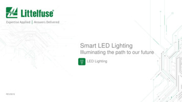
Installation diagram: 110-230V motion sensors connected to the controllerPhoto to the left shows our product STP-4811 — aset of two relays in a single-rail case T-35. This setmakes it possible to separate 230 V voltage comingsimultaneously from two motion sensors.Set of two relays STP-48118www.stairslight.com
Assembly diagram of motion sensors CRN-5891 connected to the controllerby a set of relays STP-4811NOTE: The knob „Time” in the sensors must be set to the minimum position!Installation of motion sensors in order to work properlyis extremely difficult. The visualization presented here maybe helpful.We recommend the sensorto be tilted down, so it „sees”only a portion of the first step.The top of the Fresnel lens should be covered with an opaquematerial.The motion sensor mounted on the wall9www.stairslight.com
Motion sensors for 5-12V voltageLow voltage sensors differ in dimensions, capabilities and working principle. We will brieflydiscuss all of them. For detailed information, please refer to the instructions for each type of sensor.Motion Sensor 12V wall mounted with twilight CRN-5480The CRN-5691 is a motion sensor for 12V voltage with wallmounted case for applications as a device that triggers controllerswhen motion of an object is detected. The sensor is cooperatingwith lighting controllers for stairs. The sensor detects objectsemitting infrared (heat) radiation, such as people or animals.The sensor sends a fixed-length pulse (about 5 sec) after motiondetection. The pulse has a negative level and can be connecteddirectly to the controller input. A special feature of the sensor isthe twilight sensor instaled.Miniature motion sensor 5V CRN-5686 with sensitivity adjustmentThe CRN-5686 is a subminiature motion sensor for 5V voltage for applications as a device that triggers controllers whenmotion of an object is detected. The sensor is cooperating withlighting controllers for stairs. The sensor detects objects emittinginfrared (heat) radiation, such as people or animals. The sensorsends a fixed-length pulse (about 5 sec) after motion detection.The pulse has a negative level and can be connected directly tothe controller input.Standard motion sensor 12V CRN-5481The CRN-5481 sensor fits freely into a 60 mm mountingbox. Dimensions: 32x24x18 mm. The sensor has a wide rangeof sensitivity adjustment, as well as a removable large bowl thatcan be accurately outlined to reduce the field of view. It can bepowered from the same voltage (12V) as LEDs.Compact Twilight Motion Sensor 12V CRN-5684A special feature of the CRN-5684 sensor is the twilight sensorinstalled. It blocks the work of the sensor if the light level exceeds the set value. The sensor fits freely into a 60 mm mountingbox. Dimensions: 26x24x18 mm. The sensor has a wide rangeof sensitivity adjustment, as well as a removable large bowl thatcan be accurately outlined to reduce the field of view. It can bepowered from the same voltage (12V) as LEDs. It has a diodesignaling the sensor pulse.10www.stairslight.com
Ultrasonic sensor 12V CRN-5462The CRN-5462 ultrasonic motion detector has a preciselyadjustable field of view range from 1 cm to 250 cm. The field ofview can have a selected depth and distance from the sensor inthe range of 1 cm to 250 cm. Dimensions: 46x20x20 mm. Thesensor fits freely into a 60 mm mounting box. It can be suppliedwith the same voltage as the LED diodes. It has a diode signalingthe sensor pulse.Installation of sensorsEach low voltage sensor can be directly connected to the controller input. It is important that thesensor and the controller itself are connected in the correct way.On the back of the sensor is a connector for connecting wiresleading to the controller. To facilitate assembly, to each sensoris added the connector to soldering wires. You should keep thecorrect order of wires according to the description on the sensorconnector.It is recommended to use colored wires with a possibly smallcross-section, eg a telephone cable harness. Please note thatany mistake in connecting wires, especially power supplies, candamage the sensor or controller. To facilitate assembly, to eachsensor is added the connector to solderingThe sensor’s angle of view can be adjusted by gluing the sensor’s bowl (removed) from the inside with a white insulating tape so that it does not see people passing by. For the ultrasonic sensor,select and set the work zone.The sensors can be mounted in a skirtingboard or bound. It’s best to use the so-called framewith end cap. A hole should be drilled in the cap with the diameter of the sensor bowl or with thediameter of the emitters.Before installing the sensors, their operating time and sensitivity must be set to minimum. In thecase of sensors having a jumper for selecting the mode of operation with or without support (triggering), select the „non-repeatable trigger” position.Two sets of sensors prepared in this way should be installed in a suitable place near to the firstand last stage.The diagram on the next page shows exactly how the whole set is built with the use of 12Vmotion sensors.11www.stairslight.com
Motion sensors for voltage 12VInstallation diagram: 12V motion sensors connected to the controllerBefore mounting the sensors, please set their time of action and sensitivity to a minimum. In thecase of sensors with a jumper used to select the operating mode with or without triggering, choosethe position “non-repeatable trigger.”These two sets of adapters with sensors should be mounted in their appropriate place by theside of the first and the last step.The controller can handle additional input located on the mezzanine. In such a case, an additionalmotion sensor (or an additional push button) should be placed so as to detect the entrance a personto the staircase mezzanine, but so it does not react to people walking up the stairs.After detecting a person entering the stairs to the mezzanine, the controller will immediatelystart the lighting of the whole staircase and turn it off after approx. 20 seconds. The diagram on theneighboring side shows such a solution.12www.stairslight.com
Mezzanine case.Installation diagram shows connecting three motion sensors 12V to the controller.An optional button is not shown.Setting the motion sensorsThis is one of the most difficult operations — it requires patience and precision. First of all, adjustthe sensitivity of the sensor in order to have it react effectively to a person entering the staircase. Thesecond problem to solve is that the sensor should not react to a person coming down the stairs - that itdoes not re-activate the fading lighting of the stairs. The best way is to cover the sensor hemispheresrespectively. Of course, the arrangement of the sensors is also very important — usually they areplaced on the right side of the stairs looking in the direction of movement (‘right-hand traffic’). Somesensors have an additional adjustable parameter - the so-called ‘dead time’. It is the time measuredafter an impulse, during which the sensor does not respond to the next person entering the fieldof its operations. When the mentioned parameters are adjusted patiently, the sensors will functionproperly, providing a satisfactory lighting of the stairs.Remote controlController programs can be set remotely by the transmitter SRF-4884. For the example shownabove, A button activates the animation upward, B button turns on continuous light, C button changesthe programs, and D button changes options for the selected program.13www.stairslight.com
Changing RGB programsTo change the RGB program briefly press the CON (steady light) button to turn on the lights thewhole staircase. Now, briefly pressing the PRG button, you can sequentially change RGB programsof the controller. The effect is visible immediately on the stairs. When changing programs will bedisplayed colored markers. This allows you to assess where in the list of programs just are. See alist of RGB programs on page 3.Most programs have additional options changed by pressing the OPT button. Most often it is thespeed of change of the color or the selection of a particular color. Set program and its options arestored by the controller.The controller is factory-enabled range of special programs (FX). This range can be switched onand off. After turning off the number of programs is restricted to the basic programs and after program14 (black marker - off), the controller will go directly to the program 1.To lock and unlock FX mode, hold both (PRG and OPT) buttons in for about 15 seconds until theLEDs changes from blue to either red (locked out) or green (unlocked). If both program and optionbuttons are pressed together briefly the unit will revert to program 1.After any buttons have been pressed the changes will be stored to non volatile memory and theunit will power up in that mode until further changes are made.When you change the program, turn off the lighting of the stairs again briefly pressing the ECON.After approx. 5 seconds, the controller will return to normal operation.Rotation programs can be enabled by changing the parameters of the controller - see the nextchapter point: Flicker 4: Automatic switching programs RGB.Adjusting the controllerSetting the parameters should be performed only when strictly necessary, after reading thefollowing description carefully. For your greater safety, changing these parameters is blocked bythe factory. They can be unblocked by the user only when he understands the method according towhich they are set.To start the parameter setting mode, press and hold the SETUP button for about 20 seconds (itstars lighting up the steps) until the green LED fades out. Release the button to go on to the controllerparameter setting mode. A few seconds flickering of the LED corresponds to each parameter. Youcan set or change 12 parameters, and therefore there will be twelve consecutive flickers of the LED.In order to facilitate counting them, a marker is inserted after every five flickers – a two second LEDconstant light. To select a specific parameter to be changed, you should count each flicker and then,after a suitable number of flickers, press the SETUP button. If you do not want to change a parameter,skip the flickering without pressing the button. If at the parameter setting mode the SETUP button isnot pressed, none of the parameters will change.Adjusting controller parameters diagramThe principle of setting the parameters is as follows: setting each parameter is indicated by arapid flickering of the green LED. If during this flickering the SETUP button is pressed and held, then,depending on the parameter, you will see from one to several dozens of slow LED pulsees. Setting14www.stairslight.com
the parameter takes place after a release of the button after the desired number of pulsees or justafter the end of the flickering. During the flickering, if the SETUP button is not pressed, after a shorttime of the LED fading out, flickering of the next parameter will appear and so on until the end of thesetting mode. If the given flicker is omitted, the corresponding parameter will not be changed. Thisallows you to set only one parameter, without any of the others. Notice: if the SETUP button is pressed during the flickering and released immediately after it, but before the first pulse, the parameterwill return to the factory setting.After setting the selected parameter, the controller immediately returns to a stand-by state, waitingfor a signal from pulse sensors or push buttons. There are no flickers for other parameters. To setanother parameter, use of the SET button again.Setting a single parameterDescription of parametersFlickering 1 – Count of stairs.The controller is factory-set for 15 steps. This can be changed with this parameter. The range isfrom 5 to 23 steps. To change the number of steps, press and hold the SET button during the firstflickering. You should release the button after the right number of flicks. Eg., to set 18 steps, releasethe button after 18th flick.Flickering 2 – Count of rails.The controller is factory-disabled for lighting the railing. You can turn on one or two rails. Note:two rails should be set only if in the entire staircase there are handrails on both sides. In other cases,such as one handrail divided into two sections, set the operation to one handrail! Releasing the buttonafter the first slow pulse sets the lighting for one rail, and letting go after the second pulse – setsthe lighting for two rails. Releasing the button after the end of flickering and before the first pulseswitches off the backlight railing.15www.stairslight.com
Flickering 3 – Count of stairs to a mezzanine.The controller also can be used for a staircase with an entrance to a mezzanine. This casesupports the third detector (or button) connected to the input No. 3. The controller is factory-set tono animation at the entrance to the mezzanine - turn on the whole staircase. However, you can startthe animation consisting of successive lighting of stairs up and down from the mezzanine. You willneed to set in this option, which is the number of stairs from the bottom to the mezzanine. To setthe number of steps, press and hold the SET button during the third flickering. You should releasethe button after the right number of pulses. Eg., to set 8 steps, release the button after 8th pulse.To re-enable lighting up stairs upon entering mezzanine you must let go off the button immediatelyafter the third flickering.Flickering 4 – Animation type.The controller has 3 different light animation programs (for upward direction): WAVE – stairs lightup one after another,, CASCADE – the light „jumps” fast from top to bottom, lighting up the steps,ELEVATOR – three lighted steps slowly „move” to the top of the staircase. When descending, thedirection of the animation changes suitably. In the factory, the animation cycle is preset in the following way:: first WAVE, then CASCADE and finally ELEVATOR, and then the sequence is repeated.Releasing the button after the first pulse turns the program 1 (Wave), the second pulse turns onprogram 2 (Cascade), and releasing the button after the third pulse switches permanently to programNo. 3 (Elevator). To return to the cycle animation function, the button should be let go immediatelyafter the end of the flickering.Flickering 5 – Lighting of the steps.You can set the time of a slow lighting of the steps. This gives an effect which is more thanpleasing than turning on a sharp light at full power. The factory setting is 10, which corresponds to0.5 second time of single step illumination (a total of 10 seconds for 20 steps). Releasing the buttonafter the end of the flickering sets the time to the default value (approx. 0.5 sec. – 10 units). However,if the button is held on, you can set a different, shorter or longer period of time for the illuminat
It can also control lighting of one or two handrails. If there is no handrail, the controller can serve to turn on ceiling lights (12V). All the parameters of the controller can be set by the user. In the original (factory) settings, the controller is ready for lighting up 20 steps, without lighting