Transcription
Chapter 6Displaying andAnnotatingAlignmentsCopyright 2015. John Wiley & Sons, Incorporated. All rights reserved.As you’ll find with nearly every design component you create for a landdevelopment project, creating the design is only half the job—you mustalso address the graphical appearance and annotation of what you’ve created. Alignments serve as the basis for further design of a linear feature,but they also serve as a means of expressing the geometry of the feature toreviewers and contractors. The alignment by itself doesn’t tell this story inenough detail and must therefore be stylized and annotated appropriately. Inaddition, alignments often serve as baselines used to express the location ofother features within the project.In this chapter, you’ll learn how to use various styles and annotations toconvey important information about alignments.In this chapter, you’ll learn to: Apply alignment styles Apply alignment labels and label sets Create station/offset labels Create segment labels Apply tag labels and tablesChappell, Eric. AutoCAD Civil 3D 2016 Essentials : Autodesk Official Press, John Wiley & Sons, Incorporated, 2015. ProQuest Ebook etail.action?docID 2052358.Created from osu on 2017-07-18 11:05:16.
114Chapter 6 Displaying and Annotating AlignmentsUsing Alignment StylesCertificationObjectiveAs with other styles you have learned about, alignment styles are, as their nameimplies, used to control the appearance and behavior of alignments. By applyingdifferent styles, you can graphically distinguish between existing centerlines,proposed centerlines, and so on. You can even use styles to display an alignmentas something that is not a centerline at all, such as a property line or even a utility line. Figure 6.1 illustrates how styles enable alignments to represent manydifferent things.Copyright 2015. John Wiley & Sons, Incorporated. All rights reserved.F i g u re 6 . 1 Different alignment styles are used to represent the right-of-way, edges ofpavement, and centerlines in this drawing.If you haven’t alreadydone so, downloadand install the files forChapter 6 according tothe instructions in thisbook’s Introduction. Alignment styles have two major ways of affecting the appearance of alignments. First, they control which components of the alignment are visible, andsecond, they control the graphical properties such as layer, color, and linetype ofthe components that are displayed.Exercise 6.1: Apply Alignment StylesIn this exercise, you’ll use alignment styles to control the appearance ofalignments. Because alignmentsare strictly 2-D objects,the drawings in thischapter have not beenconfigured with multiple viewports.1. Open the drawing named Alignment Styles.dwg located in theChapter 06 class data folder.The drawing contains a dozen different alignments that areintended to serve different purposes. Currently, all the alignmentslook the same because they have been assigned a style of Standard.Chappell, Eric. AutoCAD Civil 3D 2016 Essentials : Autodesk Official Press, John Wiley & Sons, Incorporated, 2015. ProQuest Ebook etail.action?docID 2052358.Created from osu on 2017-07-18 11:05:16.
Using Alignment Styles1152. Zoom in to the alignment representing the centerline of EmersonRoad. Select the alignment, right-click, and select Properties.3. Change the style to C-ROAD-CNTR-E, as shown in Figure 6.2. This displays the alignment as a simple seriesof lines and curves onthe existing road centerline layer.F i g u re 6 . 2 Assigning an alignment style in the Properties windowCopyright 2015. John Wiley & Sons, Incorporated. All rights reserved.4. Press Esc to clear the selection of the alignment. Select the JordanCourt centerline alignment, and change its style to C-ROAD-CNTR.This displays this alignment as a simple series of lines and curveson the proposed road centerline layer.Press Esc each timeyou change a style sothat you can see thetrue appearance of thealignment withoutthe effect of beingselected.5. Pan south so that you can see the curves in the Jordan court centerline alignment. Change the style of this alignment to C-ROAD-CNTRWith Markers.With this style, markers are placed at the beginning, end, points ofcurvature (PCs), points of tangency (PTs), points of reverse curvature(PRCs), and points of intersection (PIs). In addition, line extensionsare displayed with the tangents extending to the PI markers. Youwould use this style for the polished look of a final plan but probablynot for design. 6. Pan south until you can see the Madison Lane alignment. Changethe style of this alignment to Layout. 7. For the alignments that run parallel to the Jordan Court centerlineand extend the full length of the centerline, assign the C-ROADRWAY style.This displays the alignments on the right-of-way layer, enablingthem to take on the appearance of property lines. Chappell, Eric. AutoCAD Civil 3D 2016 Essentials : Autodesk Official Press, John Wiley & Sons, Incorporated, 2015. ProQuest Ebook etail.action?docID 2052358.Created from osu on 2017-07-18 11:05:16.You would use thisstyle for analysis purposes during design,not for the polishedlook of a final plan.You can select bothright-of-way alignments and assign theC-ROAD-RWAY style toboth of them at onceusing the Propertieswindow.
116Chapter 6 Displaying and Annotating Alignments8. For the remaining alignments that represent the edges of pavement,change the style to C-ROAD-EDGE.This displays the alignments on the edge-of-pavement layer.9. Save and close the drawing.You can view the results of successfully completing this exercise by openingAlignment Styles - Complete.dwg.Applying Alignment Labels and Label SetsCertificationObjectiveAlignments (and, as you’ll learn later, profiles) have a special kind of annotationthat is applied either to the entire alignment at once or to a range of stationswithin the alignment. This annotation repeats at specified increments or whenspecific types of geometry are encountered. This type of annotation is very useful because it changes as the alignment changes, even if new geometry is addedor the length of the alignment changes. In all, you can add seven types of alignment labels in this way. This chapter doesn’t cover all seven types, but you’lllearn about the following three alignment label types:Copyright 2015. John Wiley & Sons, Incorporated. All rights reserved.Major Station Labels Placed at the major station increment, which is largerthan the minor station increment. They typically include a tick mark along witha numerical label calling out the station.Minor Station Labels Placed at the minor station increment, which issmaller than the major station increment. These typically consist of tick marks.Geometry Point Labels Placed at key geometric points along the alignment,such as the beginning of the alignment, ending of the alignment, places wherethere are curves, and so on. If you haven’t alreadydone so, downloadand install the files forChapter 6 according tothe instructions in thisbook’s Introduction.Exercise 6.2: Apply Labels to AlignmentsIn this exercise, you’ll use the Add/Edit Station Labels command to add stationlabels, station ticks, and geometry labels to the Jordan Court alignment.1. Open the drawing named Alignment Labels.dwg located in theChapter 06 class data folder.2. Click the Jordan Court alignment. Then click Add Labels Add/EditStation Labels on the contextual ribbon tab.Chappell, Eric. AutoCAD Civil 3D 2016 Essentials : Autodesk Official Press, John Wiley & Sons, Incorporated, 2015. ProQuest Ebook etail.action?docID 2052358.Created from osu on 2017-07-18 11:05:16.
Applying Alignment Labels and Label Sets1173. In the Alignment Labels dialog box, do the following:a. For Type, verify that Major Stations is selected.b. For Major Station Label Style, verify that Parallel With Tick isselected; then click Add.c. For Increment, enter 50 (20) to indicate the number of feet(meters) to increment, and then click OK.4. Zoom in, and examine the labels that have been created.Notice that a tick mark and label have been placed at 50-foot(20-meter) increments along the alignment.5. Click the Jordan Court alignment, and launch the Add/EditStation Labels command as you did in step 2.6. In the Alignment Labels dialog box, do the following:a. For Type, select Minor Stations. Remember that valueslisted in parenthesesare not conversionsbut values that wouldmake sense in a metricenvironment. Although50 feet and 20 metersaren’t equal, each is areasonable incrementfor stationing.b. For Minor Station Label Style, verify that Tick is selected; thenclick Add.Copyright 2015. John Wiley & Sons, Incorporated. All rights reserved.c. Change Minor Station Increment to 10 (5) to indicate the number of feet (meters) to increment, and then click OK.7. Examine the alignment once more.Now you should see tick marks at 10-foot (5-meter) increments,which means there are four (three) minor tick marks between themajor tick marks and labels.8. Launch the Add/Edit Station Labels command again, as you did instep 2. In the Alignment Labels dialog box, do the following:a. For Type, select Geometry Points.b. For Geometry Point Label Style, verify that Perpendicular WithTick And Line is selected; then click Add.c. In the Geometry Points dialog box, uncheck all boxes exceptTangent-Curve Intersect, Curve-Tangent Intersect, and ReverseCurve-Curve Intersect.d. Click OK twice to dismiss the Geometry Points and AlignmentLabels dialog boxes.Chappell, Eric. AutoCAD Civil 3D 2016 Essentials : Autodesk Official Press, John Wiley & Sons, Incorporated, 2015. ProQuest Ebook etail.action?docID 2052358.Created from osu on 2017-07-18 11:05:16. You can use the buttonin the top-right cornerof the dialog box toclear all the checkboxes quickly. Theboxes you check willtake care of PCs, PTs,and PRCs, respectively.
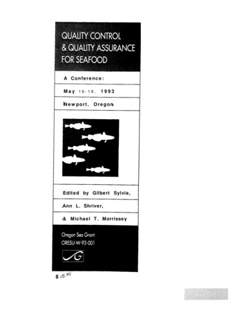
118Chapter 6 Displaying and Annotating Alignments9. Press Esc to clear the selection. Examine the alignment labels, andnote the labels at the PCs, PTs, and PRC, as shown in Figure 6.3.Geometry PointLabelsF i g u re 6 . 3 Geometry point labels displayed on the Jordan Court alignment10. Save and close the drawing.You can view the results of successfully completing this exercise by openingCopyright 2015. John Wiley & Sons, Incorporated. All rights reserved.Alignment Labels - Complete.dwg.Using Alignment Label SetsAs you might guess, the collection of labels used in the previous exercise is quitecommon: station and tick at the major station, just a tick at the minor station,and labels calling out key geometric features. What if you could gather thosethree label types together in a nice, neat package and apply them all at once?That’s the exact purpose of a label set. If you haven’t alreadydone so, downloadand install the files forChapter 6 according tothe instructions in thisbook’s Introduction.Exercise 6.3: Leverage Alignment Label SetsIn this exercise, you’ll use an alignment label set to capture the label configuration for Jordan Court and make it available for easy transfer to Madison Lane.1. Open the drawing named Alignment Label Sets.dwg located in theChapter 06 class data folder.2. Click the Jordan Court alignment. Then click Add Labels Add/EditStation Labels on the contextual tab of the ribbon.Chappell, Eric. AutoCAD Civil 3D 2016 Essentials : Autodesk Official Press, John Wiley & Sons, Incorporated, 2015. ProQuest Ebook etail.action?docID 2052358.Created from osu on 2017-07-18 11:05:16.
Applying Alignment Labels and Label Sets1193. In the Alignment Labels dialog box, click Save Label Set.4. In the Alignment Label Set dialog box, on the Information tab, enterM50 Stations & m10 Ticks & Geometry Points (M20 Stations & m5Ticks & Geometry Points) in the Name field.5. Click OK twice to close the Alignment Label Set dialog boxand the Alignment Labels dialog box.6. Press Esc to clear the selection of the Jordan Court alignment. Clickthe Madison Lane alignment, and then click Add Labels Add/EditStation Labels on the contextual tab of the ribbon.7. In the Alignment Labels dialog box, click Import Label Set.8. Select M50 Stations & m10 Ticks & Geometry Points (M20 Stations& m5 Ticks & Geometry Points), and then click OK. M50 stands for a majorstation incrementof 50 feet, and m10stands for a minorstation increment of10 feet in the imperialsystem. Similarly, M20stands for a majorstation increment of 20meters, and m5 standsfor a minor stationincrement of 5 metersin the metric system.9. Click OK to dismiss the Alignment Labels dialog box.Copyright 2015. John Wiley & Sons, Incorporated. All rights reserved.10. Press Esc to clear the selection. Examine the Madison Lane alignment (see Figure 6.4), and note that the label set applied here is thesame as the label set that was applied to Jordan Court.F i g u re 6 . 4 The Madison Lane alignment after the label set has been applied11. Save and close the drawing.You can view the results of successfully completing this exercise by openingAlignment Label Sets - Complete.dwg.Chappell, Eric. AutoCAD Civil 3D 2016 Essentials : Autodesk Official Press, John Wiley & Sons, Incorporated, 2015. ProQuest Ebook etail.action?docID 2052358.Created from osu on 2017-07-18 11:05:16. Your CAD manageror other authorizedperson can create labelsets and store themin your company template so they’re alwaysthere for you to use.
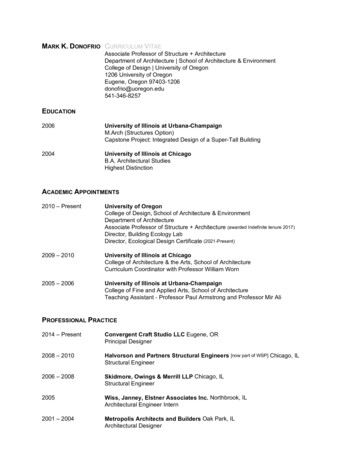
120Chapter 6 Displaying and Annotating AlignmentsEditing Alignment Labels This Ctrl key trickworks for many typesof labels that exist ingroups. If you haven’t alreadydone so, downloadand install the files forChapter 6 according tothe instructions in thisbook’s Introduction.Copyright 2015. John Wiley & Sons, Incorporated. All rights reserved. Notice that the rightof-way line is passingthrough the geometrypoint labels. Theselabels should be movedbeyond the right-ofway line, which you’lldo in the next fewsteps.Working with alignment labels is a bit different than working with other labelsbecause alignment labels exist in groups. If you click a major station label, forexample, all the major station labels for the entire alignment will be selected.So, what if you want to change something about just one label? The answer is touse your Ctrl key when selecting individual labels in a group.Another type of label edit that you’ll be introduced to in this chapter is flipping.Flipping a label simply means switching it over to the other side of the line.Exercise 6.4: Edit Alignment LabelsIn this exercise, you’ll edit the labels for Jordan Court such that the geometrylabels are moved outside the right-of-way lines. You’ll also flip a geometry pointlabel and grip-edit an individual station label to resolve a labeling conflict.1. Open the drawing named Editing Alignment Labels.dwg located inthe Chapter 06 class data folder.2. Click one of the geometry point labels on the Jordan Court alignment. Then click Edit Label Group on the contextual ribbon tab thatappears.3. Click in the Style column to the right of Geometry Points. SelectPerpendicular With Tick And Line – Offset, and click OK. The labels are nowshown outside theright-of-way line (seeFigure 6.5).F i g u re 6 . 5 Changing the style of the geometry point labels improves their appearance andreadability by moving them outside the right-of-way line.Chappell, Eric. AutoCAD Civil 3D 2016 Essentials : Autodesk Official Press, John Wiley & Sons, Incorporated, 2015. ProQuest Ebook etail.action?docID 2052358.Created from osu on 2017-07-18 11:05:16.
Creating Station/Of f set L abels1214. Click OK to dismiss the Alignment Labels dialog box, and press Esc toclear the selection.5. While holding down the Ctrl key, click the first PC label, and thenclick Flip Label on the ribbon. The label is flipped to the opposite sideof the road.6. Zoom to the intersection of Madison Lane and Jordan Court.7. Click the 0 00 (0 000) station label of Madison Lane, and then clickthe square grip that appears above the label. Drag the grip to a cleararea in the drawing.The station label is more readable in its new location, and a leaderappears that indicates the actual location of the station.8. Save and close the drawing.You can view the results of successfully completing this exercise by openingEditing Alignment Labels - Complete.dwg.Copyright 2015. John Wiley & Sons, Incorporated. All rights reserved.Dragged StateIn step 7, when you use a special grip on a label to drag it to a new location, aleader magically appears. This happens because the leader is turned on in thedragged state configuration of the label style. The dragged state of a label candramatically change the look of that label when it’s dragged to a new location.In addition to the appearance of a leader, you might see a change in text heightor orientation, the appearance of a border around the text, and several otherchanges.Creating Station/Offset LabelsAs mentioned earlier, an alignment is often used as a baseline, enabling otherfeatures to express their locations in relation to that baseline. This is typicallydone with station offset notations, and, of course, the AutoCAD Civil 3D program provides you with labels to do just that. This type of label is referred to asa station/offset label.Chappell, Eric. AutoCAD Civil 3D 2016 Essentials : Autodesk Official Press, John Wiley & Sons, Incorporated, 2015. ProQuest Ebook etail.action?docID 2052358.Created from osu on 2017-07-18 11:05:16. Note how the 0 00(0 000) station labelfor Madison Lane isconflicting with thecenterline of JordanCourt.
122Chapter 6 Displaying and Annotating AlignmentsIf you haven’t alreadydone so, downloadand install the files forChapter 6 according tothe instructions in thisbook’s Introduction. Unlike the label groups you learned about earlier, station/offset labels standalone instead of being part of a set. They are capable of reporting the station andoffset of a point that you select as well as the alignment name, coordinates ofthe point, and other types of information.You can create station/offset labels as either fixed or floating labels. If theyare fixed, then they hold their positions and update the station and offset valueswhen the alignment is edited. If they are floating, then they maintain their station and offset values and move with the alignment when it’s edited. Like spotelevation labels, station/offset labels are paired with a marker.Exercise 6.5: Create Station/Offset LabelsIn this exercise, you’ll add station/offset labels to define the road geometry at theintersection of Jordan Court and Madison Lane.Copyright 2015. John Wiley & Sons, Incorporated. All rights reserved. This drawing is zoomedin to the intersectionbetween Jordan Courtand Madison Lane.Your task is to labelthe station and offsetof either end of eachcurve that forms theintersection betweenthe two roads.1. Open the drawing named Station Offset Labels.dwg located in theChapter 06 class data folder.2. Click the Jordan Court alignment, and then click Add Labels Station/Offset – Fixed Point on the contextual ribbon tab.3. While holding down the Shift key, right-click and select Endpoint.4. Click the northern end of the northern arc. A new label that references the Jordan Court alignment is created at this location.5. While holding down the Shift key, right-click and select Endpoint.Then click the southern end of the southern arc.6. Press Esc twice to end the command and clear the selection of thealignment. Click the Madison Lane alignment, and then click AddLabels Station/Offset – Fixed Point on the contextual ribbon tab.7. While holding down the Shift key, right-click and select Endpoint.Click the western end of the northern arc. This label and theone created in step 7provide the stationand offset in referenceto the Madison Lanealignment.8. While holding down the Shift key, right-click and select Endpoint.Then click the western end of the southern arc.9. Press Esc twice to end the labeling command and clear the selectionof the alignment.10. Click one of the labels, and then click the square grip and drag it to anew location that is clear of other lines and text. Repeat this for theother labels to improve their appearance and readability.Chappell, Eric. AutoCAD Civil 3D 2016 Essentials : Autodesk Official Press, John Wiley & Sons, Incorporated, 2015. ProQuest Ebook etail.action?docID 2052358.Created from osu on 2017-07-18 11:05:16.
Creating Segment LabelsThe result should look similar to Figure 6.6.F i g u re 6 . 6 Station/offset labels applied to the edge-of-pavement arcs at theintersection of Madison Lane and Jordan Court11. Save and close the drawing.Copyright 2015. John Wiley & Sons, Incorporated. All rights reserved.You can view the results of successfully completing this exercise by openingStation Offset Labels - Complete.dwg.Creating Segment LabelsSo far, you have seen label groups that label the entire alignment at once andstation/offset labels that are typically used to label something other than thealignment. What about the individual parts of the alignment? How do you tellreviewers and contractors how to re-create those alignments in the field? Theanswer is segment labels. Segment labels allow you to label things such as bearings, distances, and curve data. By providing this information as text in thedrawing, you give viewers of the drawing the information they need to stake outthe alignment in the field. You’re also sharing information about the geometric“performance” of the alignment that might answer questions such as these: Arethe curves too sharp for the expected speed? Is the alignment parallel to otherimportant features? Are intersecting roads perpendicular to one another?Segment labels stand alone like station/offset labels; however, you can createthem in bulk if you so desire. For example, all the tangents of an entire alignment can be labeled at once if you choose that option when creating the labels.Chappell, Eric. AutoCAD Civil 3D 2016 Essentials : Autodesk Official Press, John Wiley & Sons, Incorporated, 2015. ProQuest Ebook etail.action?docID 2052358.Created from osu on 2017-07-18 11:05:16.123
124Chapter 6 Displaying and Annotating Alignments If you haven’t alreadydone so, downloadand install the files forChapter 6 according tothe instructions in thisbook’s Introduction.Exercise 6.6: Create Segment LabelsIn this exercise, you’ll add segment labels to define bearing, distance, and curveinformation for the Madison Lane and Jordan Court alignments.1. Open the drawing named Segment Labels.dwg located in theChapter 06 class data folder.2. Click the Madison Lane alignment, and then click Add Labels AddAlignment Labels.3. In the Add Labels dialog box, do the following:a. For Label Type, select Single Segment.b. For Line Label Style, verify that Bearing Over Distance isselected.c. For Curve Label Style, verify that Curve Data is selected, andthen click Add.Copyright 2015. John Wiley & Sons, Incorporated. All rights reserved.Notice what happens tothe bearing: It switchesfrom SW to NE (or viceversa, depending onwhere you clicked instep 4), but the numbers don’t change. 4. Zoom in, and click one of the tangents of Madison Lane.Notice the bearing and distance label that is created.5. Press Esc to end the labeling command. Click the newly created label,and then click Flip Label on the ribbon.This swaps the position of the bearing and distance.6. Select the label again, and this time select Reverse Label.7. Click Add in the Add Labels dialog box. Then click the curve andthe other tangent of Madison Lane to create two more labels in thedrawing. This improves theappearance and readability of the label andautomatically creates aleader pointing back tothe curve.8. Press Esc to end the labeling command. Click the curve label, andthen click the label’s square grip and drag it to a clear location in thedrawing.9. In the Add Labels dialog box, change Label Type to Multiple Segment.Change Curve Label Style back to Curve Data.10. Click Add, and then click anywhere on the Jordan Court alignment.All tangents and curves are labeled at once.Chappell, Eric. AutoCAD Civil 3D 2016 Essentials : Autodesk Official Press, John Wiley & Sons, Incorporated, 2015. ProQuest Ebook etail.action?docID 2052358.Created from osu on 2017-07-18 11:05:16.
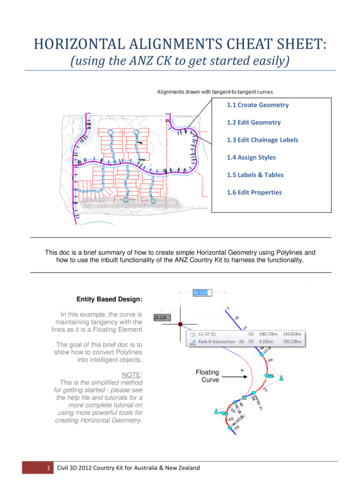
Creating Segment Labels11. Move the curve labels for Jordan Court to open areas in the drawingso that they are easier to read (see Figure 6.7).12. Save and close the drawing.F i g u re 6 . 7 Curve labels added to the Jordan Court alignment. To improvereadability, the labels have been dragged away from the alignment and into clear areas.Copyright 2015. John Wiley & Sons, Incorporated. All rights reserved.You can view the results of successfully completing this exercise by openingSegment Labels - Complete.dwg.Why Be a Bear about Bearings?If this is the first time you’ve seen bearings, you may not know what is going onhere. A bearing is a way of expressing the direction of a line. In this exercise, thebearing of the eastern tangent of Madison Lane is S67 27'02.54"W. That means ifyou face south and then turn yourself toward the west about 67 , you’ll be facingroughly in the direction that this line is pointing. Because there are 90 betweensouth and west, you’ll actually be facing more west than south.When the bearing is reversed, it’s like you’ve done an about-face and you’re nowfacing 67 east of north. This doesn’t change the appearance of the line, and itmight seem picky to distinguish between SW and NE in this case. But when youthink about it, the stationing of this road is increasing in a certain direction (westin the case of Madison Lane), which establishes the direction of the alignment.For consistency, it’s a good idea for the direction of your bearing labels to agreewith the direction of your alignment.Chappell, Eric. AutoCAD Civil 3D 2016 Essentials : Autodesk Official Press, John Wiley & Sons, Incorporated, 2015. ProQuest Ebook etail.action?docID 2052358.Created from osu on 2017-07-18 11:05:16.125
126Chapter 6 Displaying and Annotating AlignmentsUsing Tag Labels and TablesCopyright 2015. John Wiley & Sons, Incorporated. All rights reserved.Sometimes, it’s better to put all the geometric data for an alignment in a tablerather than labeling it right on the alignment itself. This can clear up a cluttered drawing and provide space for other types of annotations. You can accomplish this in Civil 3D by using tag labels and tables.A tag label is a special kind of label that assigns a number to a curve, tangent,or spiral. Common examples are C1, S1, and L1 for a curve, spiral, and tangent,respectively. Tag labels can be created ahead of time if you know you’re going to usea table, or you can convert regular labels to tag labels on the fly. In fact, you canconvert just a few of the labels to tag labels and use a combination of a table andin-place labels to convey alignment information. This is common in cases wherecertain segments of an alignment are too short to have a label fit on them nicely.As Murphy’s Law would have it, the numbers you get when creating tag labelsare almost never what you want them to be. This is no fault of the software; infact, the reason for this happening so frequently is that the software is doing itsjob. Each time you create a tag label, Civil 3D bumps the next tag number up byone. Because most designs are laid out and labeled more than once (lots more, inmost cases), your next tag number is likely to be set to something other than 1.Fortunately, Civil 3D is quite good at enabling you to correct your tag labels.There is even a Renumber Tags command designed for that specific purpose. If you haven’t alreadydone so, downloadand install the files forChapter 6 according tothe instructions in thisbook’s Introduction.Exercise 6.7: Create Tag LabelsIn this exercise, you’ll create and renumber tag labels for the Jordan Courtalignment.1. Open the drawing named Tag Labels.dwg located in the Chapter 06class data folder.2. Click the Jordan Court alignment, and then click Add Labels AddAlignment Labels on the contextual ribbon tab.3. In the Add Labels dialog box, select Multiple Segment as the labeltype.4. Verify that Circle Tag is selected for both Line Label Style and CurveLabel Style.Chappell, Eric. AutoCAD Civil 3D 2016 Essentials : Autodesk Official Press, John Wiley & Sons, Incorporated, 2015. ProQuest Ebook etail.action?docID 2052358.Created from osu on 2017-07-18 11:05:16.
U s i n g Ta g L a b e l s a n d Ta b l e s1275. Click Add, and then click anywhere on the Jordan Court alignment.Press Esc to end the labeling command.As you can see in Figure 6.8, curve and line tag labels have beencreated, but the numbering is not what it should be. You’ll addressthis in the next few steps.F i g u re 6 . 8 Curve tag labels on the Jordan Court alignment6. Close the Add Labels dialog box. Click the Jordan Court alignment,and then select Renumber Tags on the contextual ribbon tab.Copyright 2015. John Wiley & Sons, Incorporated. All rights reserved.7. On the command line, type S for settings, and press Enter.8. Change all values to 1 in the Table Tag Numbering dialog box, andclick OK.9. Starting at the beginning of the Jordan Court alignment, click eachtag label in order from start to end.10. Sav
116 Chapter 6 Displaying and Annotating Alignments 8. For the remaining alignments that represent the edges of pavement, change the style to C-ROAD-EDGE. This displays the alignments on the edge-of-pavement layer.