Transcription
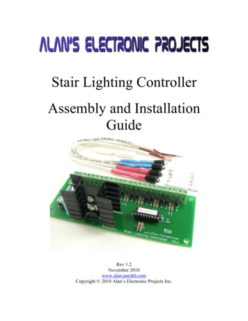
Stair Lighting ControllerAssembly and InstallationGuideRev 1.2November 2010www.alan-parekh.comCopyright 2010 Alan’s Electronic Projects Inc.
Stair Lighting Controller Assembly and Installation GuideRevision HistoryDateOctober 10, 2005Revision1.0January 24, 20061.1November 6, 20101.2Author(s)Alan Parekh,Bill AlexanderAlan Parekh,Bill AlexanderAlan Parekh2 of 41DescriptionDocument creation.Section 2.2 revision.Spelling and Grammar.Major document update.
Stair Lighting Controller Assembly and Installation Guide1. Introduction . 41.1 Concept of Operation .41.2 Lighting Unit Features .42. Kit Assembly . 52.1 Control Board Assembly.52.3 IR Transmitter Assembly .142.4 IR Receiver Assembly.193. Testing a Control Unit. 244. Field Wiring . 264.1 Mount Lighting Control Unit .264.2 Connect Power .264.3 Install Stair Lights .264.3.1 Wiring 10 or Less Stair Lights to Controller .274.3.1 Wiring 11 to 20 Stair Lights to Controller .274.4 Install Infrared Beams .274.4.1 Determine IR Beam Location .284.4.2 Install IR Beams.284.4.3 Wiring IR Beam Sensors to Controller .285. System Setup and Testing . 295.1 Entering Setup Mode.295.2 IR Beam Alignment Confirmation.295.4 System Testing .296. Programming Light On Duration. 306.1 Entering Program Mode.306.2 Reading Program Mode On Time Code .306.3 Changing the Program Mode On Time Code .317. Maintenance. 318. Troubleshooting . 319. Optional System Features . 339.1 Installing Laser Beams.339.2 Auxiliary Output .349.3 Installing Piezo Buzzer .349.4 Use a Normally Open or Normally Closed Contact Input .3510. Stair Lighting Wire Calculation Guide . 3511. Appendix . 3811.1 Stair Light Control Board Schematic.3811.2 Stair Light External Connections .3911.3 Circuit Board Layout Diagram .4011.4 Circuit Board Component Photo.413 of 41
Stair Lighting Controller Assembly and Installation Guide1. IntroductionThank you for purchasing a Stair Lighting kit. This document will walk you through theassembly and installation of your stair lighting controller kit. There are many optionsavailable when purchasing this kit so some sections might not pertain to your situation. Forexample if you purchased the unit fully assembled you can skip directly to the FieldWiring section. Each section will also list the tools required.1.1 Concept of OperationThe Lighting Control Unit is microcontroller based, what this means is there is a small selfcontained computer that controls the unit. Stair lights are wired up to the control unit, anIR (Infrared) transmitter and receiver are used at the top and bottom of the stairs to create abeam of invisible light. When this beam is broken (crossed) the Lighting Control Unit willbe able to sense this and turn on the lights. The controller performs a slow ramp of thelights or lights them up one step at a time depending on the controller purchased. Thecontroller also keeps track of which beam was broken and turns off the lights following theperson. For example if the bottom beam was broken to turn the lights on the lights will turnoff following the person up the stairs. The lights fade out slowly to provide a nice visualeffect.1.2 Lighting Unit Features 10 separate stair lighting outputs. Each output can drive 2 stair lights allowing forbetween 1 and 20 lights to be controlled. Please note that even though 20 lights canbe connected all 20 will not have independent control, in this case every pair oflights would mirror each other. A more likely scenario would be 11 stairs, in thiscase it could be wired so that each stair has independent control and the 2 centerones would act as one, fading together etc.2 separate IR (Infrared) beam sensor inputs. This allows independent sensing of howthe stairs were entered allowing separate patterns to turn the lights off. The kit comeswith the 2 resistors that would allow laser pointers to be installed instead of theinvisible supplied beam.Programmable on time. You will be able to use the default 20 second on time orchange it to something shorter or longer if you need to.Flash memory storage. The on time you select will be retained even if power isremoved from the control unit, this is because it is stored in flash memory.Versatile Power Requirements. The unit can be powered from any plug in class 2wall transformer that outputs anything from 9 to 12VDC at 500mA (.5A) or greater.Reverse Polarity Protection. If the power is connected with reverse polarity the unitwill not be damaged, it will just not power up.Lighting Output Short Circuit Protection. If one of the lighting outputs areaccidentally short circuited the control unit will self current limit to protect theoutputs. Once the short is removed normal operation will resume immediately.4 of 41
Stair Lighting Controller Assembly and Installation Guide Correct electronic installation practices should still be followed such as powering theunit down when making any electrical connections.Auxiliary Output. This is meant for those that are advanced and want to controlsomething else when the lights are on. There is an output that is provided that cansink up to 20mA at 5V when the lights are on. For those that are not electronicallysavvy you can just ignore this.2. Kit Assembly2.1 Control Board AssemblyTo assemble the Stair Lighting control board you will need a soldering iron, solder, wirecutters, screw driver and pliers.Many of the components of the kit are sensitive to static discharge. Before you begin it isimportant that you remove any static electricity from your body by grounding yourself.This is done by touching any grounded metal that is by the area you are going to beassembling the board. For example a bare metal computer power supply. You must groundyourself again if you walk away and return to the location you are assembling your controlboard.Many of the components look the same but if installed in an incorrect location can causedamage to the control board. It is very important to ensure that correct components areinstalled in the correct position. We are going to start by installing the shortest componentsand progress to the larger ones. When the instructions say to “install” this means to placethe leads through the required holes allowing the component to sit close to the board,soldering the component in place and trimming the leads. See the appendix for diagrams ofthe control board. Appendix 11.3 is a board diagram showing component numbers andappendix 11.4 is a picture of the completed board for a visual reference. When componentreferences are made such as R1, D1 C1 these can be found on the Appendix 11.3 diagram.1. Install all resistors. Resistors positions are marked with an “R” followed by anumber. Resistors are non polarized, this means that they can be install in eitherdirection. It is very important that the correct value of resistors be used in thecorrect location!There are three types of resistors used on the control board, 0 ohm, 220 ohm and10K ohm. The value of the resistor is represented by colored bands on the resistor.220 ohm is RED, RED, BROWN, GOLD.10K ohm is BROWN, BLACK, ORANGE, GOLD.0 ohm is BLACK.R1: 220 ohmsR2: 220 ohmsR3: 10K ohmsR4: 220 ohms5 of 41
Stair Lighting Controller Assembly and Installation GuideR5: 10K ohmsR6: 10K ohmsR7: 10K ohmsR8: 10K ohmsR9: 10K ohmsR10: 10K ohmsR11: 10K ohmsR12: 10K ohmsR13: 10K ohmsR14: 10K ohmsR15: 0 ohms, this resistor is not shown on the schematic since it is simply beingused as a jumper.R16: 0 ohms, this resistor is not shown on the schematic since it is simply beingused as a jumper.2. Install the diode. There is a single diode to install, it is polarity sensitive. Thiscomponent is listed as D1 on the schematic. The white bar on one end of the dioderepresents negative. The negative lead must be installed to match the bar shown onthe circuit board.6 of 41
Stair Lighting Controller Assembly and Installation Guide3. Install 18 pin chip socket. Do not install the microcontroller at this time! Thesocket goes in the location marked as U1, this is actually referring to themicrocontroller chip but the location is the same since the microcontroller plugsinto this socket. To orientate the socket properly, locate the notch and align it withthe notch shown on the circuit board.4. Install transistors. Transistors must be installed with the correct orientation.These components are marked as Q1 through Q11. All of the transistors are locatedadjacent to the terminal block location. Install the transistors with the curvedportion matching the diagram on the circuit board.7 of 41
Stair Lighting Controller Assembly and Installation Guide5. Install fuse holder. Do not install the fuse at this time. The fuse holder is twoseparate clips that the fuse will snap into. Install both clips. The fuse location ismarked as F1. The fuse holder clips are mounted at both ends of the fuse. It isimportant to solder the fuse holder in securely; it will take quite a bit of heat andsolder to install it properly. See the picture for an example of a proper solder joint.8 of 41
Stair Lighting Controller Assembly and Installation Guide6. Install Power on LED. The power on LED is polarity sensitive. Its location ismarked as D2. There is a flat side on the LED that represents the LED’s cathode(negative) side. Line up the flat spot with the diagram on the circuit board. Whensoldering an LED you should solder one lead then wait about 5 seconds beforesoldering the second lead. This will allow the LED to cool before soldering thesecond lead. Do not apply heat to the LED for an extended time since that willdamage the LED.7. Install terminal block. When orientating the 24 position terminal block make surethe large holes for the wires are facing away from the board. When soldering this inplace it is important that there is no space between it and the circuit board. Theeasiest way to do this is solder the end pins and a center pin. Then closely inspect itto ensure there is no gap, if there is simply reheat the solder while applying slightpressure on the terminal block. Once the 3 pins are soldered correctly you can nowsolder all of the other pins. If the terminal block came as many small sections slidethem together before soldering them in place.9 of 41
Stair Lighting Controller Assembly and Installation Guide8. Install capacitors. There are four capacitors to install, three of these are polarizedand must be installed in the correct orientation. Capacitors C1, C2 and C3 arepolarized. There is a stripe on one side that points to the negative lead. Insert thecapacitors based on the polarity marked on the circuit board. Since C4 has nopolarity it can be installed in any direction. Note C4 is a very small capacitor, itmight not have any identification on it that specifies it to be a 0.1uF capacitor.These capacitors are usually tiny rectangular devices where the component is thesize of a match head.C1: 1000uFC2: 0.33uFC3: 470uFC4: 0.1uF10 of 41
Stair Lighting Controller Assembly and Installation Guide9. Assemble heatsink and voltage regulator. There are two pieces that make up asingle heatsink. Place the heatsink pieces back to back and insert the first nut andbold into one of the two heatsink holes. Bolt the voltage regulator to the heatsinkusing the second heat sink hole. The metal back of the regulator must be placed flatagainst the heatsink.11 of 41
Stair Lighting Controller Assembly and Installation Guide10. Install voltage regulator/heatsink assembly. The voltage regulator must beinstalled in the correct orientation. With the terminal block location at the top,install the regulator so that the face of the regulator (side with writing) is facingaway from the terminal block. When soldering it may be easier if something suchas a screwdriver is used to raise the board to the same height as the heatsink.11. Install fuse. Snap the 1 Amp fuse into the fuse holders. Ensure that the metal endcaps of the fuse are being held by the clips and not the glass portion of the fuse.12 of 41
Stair Lighting Controller Assembly and Installation Guide12. Install Chip. The chip is very sensitive to static electricity. Ground yourself againbefore removing it from its antistatic package. Do not handle the chip excessively;simply insert it into the socket that was installed in step 3. If the chip pins do notline up very easily it may be necessary to gently adjust the width of the pins byapplying slight pressure against a table. When aligning the chip, place the notch ofthe chip in the same orientation as the notch on the socket.13 of 41
Stair Lighting Controller Assembly and Installation Guide2.3 IR Transmitter AssemblyTo assemble an IR Transmitter you will need a soldering iron, solder, wire cutters andpliers. Another tool that makes assembly very simple is a set of “Helping Hands”. This is atool that has 2 clips that can hold electronic parts in place while you solder them together.If you use a set of helping hands wrap the clips with electrical tape to protect theelectronics.CAUTION: Read the caution in the Stair Light Assembly section. It also applies to the IRtransmitter. It is also very important that the IR transmitter is only connected to the IR porton the Lighting Control Unit located at terminals 3 and 4. Connecting the transmitter toany other terminals (or direct power) will cause damage to the unit.The IR Transmitter assembly consists of a current limited IR LED that can be directlycontrolled by the Stair Lighting Controller to produce a beam of invisible light, this lightwill be used to detect people entering the stairs. The wire leads are 10 inches long; this islong enough to connect the IR Transmitter to a wire that runs to the controller. Each IRTransmitter includes 2 crimp connectors for this purpose.14 of 41
Stair Lighting Controller Assembly and Installation Guide1. Prepare the cable. Cut a section of cable to 10 inches. Strip the end off the cableexposing the 4 conductors inside.2. Remove extra conductors. We only require the red and black conductors; theyellow and green ones can be cut out. Cut them as close to the jacket as possible.3. Install Resistor R1. Install the 7.5 ohm resistor in the R1 location of the LEDmounting board.The value of the resistor is represented by colored bands on the resistor.7.5 ohms is BROWN GREEN GOLD GOLD.15 of 41
Stair Lighting Controller Assembly and Installation Guide4. Install Resistor R2. Install the 7.5 ohm resistor in the R2 location of the LEDmounting board. It can be tricky to install since one of the leads will be under R1,the trick is to trim the lead before inserting the resistor and solder it from the top.The value of the resistor is represented by colored bands on the resistor.7.5 ohms is BROWN GREEN GOLD GOLD.5. Install the Transmit LED. Install the transmit LED in the 5 and 6 position of theLED mounting board. The flat side and short lead goes into position 5. Bend theleads over leaving about a 1/4 inch of lead extending from the front of the board.Solder the LED in place one lead at a time allowing 5 seconds of cooling timebefore soldering the second lead.16 of 41
Stair Lighting Controller Assembly and Installation Guide6. Connect wire to board. Now that the transmitter board is complete you canconnect it to the wires that we stripped earlier. The black wire gets installed inposition 1 and the red wire gets installed in position 2.7. Install red heat shrink. To protect all of your hard work slide the red heat shrinkover the resistors and the exposed wires. Carefully heat the heat shrink using anappropriate heat source such as a heat gun. Be very careful not to heat thetransmitter LED since heat will damage the device.17 of 41
Stair Lighting Controller Assembly and Installation Guide8. Prepare the wire connection end. Strip the end and remove the wires that are notbeing used, only keep the black and red wire. Then strip the ends of the black andred wires.9. Install bezel. Gently push the bezel into place. This unit is now complete.18 of 41
Stair Lighting Controller Assembly and Installation Guide2.4 IR Receiver AssemblyTo assemble an IR Receiver you will need a soldering iron, solder, wire cutters and pliers.Another tool that makes assembly very simple is a set of “Helping Hands”. This is a toolthat has 2 clips that can hold electronic parts in place while you solder them together. Ifyou use a set of helping hands wrap the clips with electrical tape to protect the electronics.CAUTION: Read the caution in the Stair Light Assembly section. It also applies to the IRreceiver.The IR Receiver assembly consists of a resistor in series with an IR transistor. The receiverdetects the invisible light produced by the IR transmitter and then sends a signal to the stairlight controller. The wire leads are 10 inches long; this is long enough to connect the IRReceiver to a wire that runs to the controller. Each IR Receiver includes 3 crimpconnectors for this purpose.19 of 41
Stair Lighting Controller Assembly and Installation Guide1. Prepare the cable. Cut a section of cable to 10 inches. Strip the end off the cableexposing the 4 conductors inside.2. Remove extra conductor. We require all but the green conductor. Cut the greenwire out as close to the jacket as possible.3. Install Resistor R1. Install the 47K ohm resistor in the R1 location of the LEDmounting board.The value of the resistor is represented by colored bands on the resistor.47K ohms is YELLOW VIOLET ORANGE GOLD.20 of 41
Stair Lighting Controller Assembly and Installation Guide4. Install the Receiver. Install the IR transistor in the 5 and 6 position of themounting board. The flat side and short lead goes into position 6. Bend the leadsover leaving about a 1/4 inch of lead extending from the front of the board. Solderthe device in place one lead at a time allowing 5 seconds of cooling time beforesoldering the second lead.21 of 41
Stair Lighting Controller Assembly and Installation Guide5. Connect wire to board. Now that the receiver board is complete you can connectit to the wires that we stripped earlier. The red wire gets installed in position 2, theblack wire gets installed in position 3 and the yellow wire gets connected toposition 4.6. Install blue heat shrink. To protect all of your hard work slide the blue heatshrink over the resistor and the exposed wires. Carefully heat the heat shrink usingan appropriate heat source such as a heat gun. Be very careful not to heat the IRtransistor since heat will damage it.22 of 41
Stair Lighting Controller Assembly and Installation Guide7. Prepare the wire connection end. Strip the end and remove the green wire that isnot being used. Then strip the ends of the wires.8. Install bezel. Gently push the bezel into place. This device is now complete.23 of 41
Stair Lighting Controller Assembly and Installation Guide3. Testing a Control UnitOnce the board has been constructed it is a good idea to fully test it before you start on thefield wiring. Follow the following steps and ensure you get the correct results. These stepsare assuming that you have just completed all of the steps in the Control Board Assemblysection. During the testing it is very important to ensure you are working on a non metallicsurface with no metal particles on it (no resistor clippings etc). It is also important that nowires are connected or removed while the unit has power attached. To power down thecontrol unit unplug the wall transformer and consider the circuit dead 10 seconds after thepower on indicator goes out. The board goes through a power up cycle for about 1 minutewhen powered up, after this power up time the controller test can be performed.To use this table perform the task in the “Do This” column, check to see that you get theexpected result that is listed in the “Check Results” column. If you do not get the expectedresult the “Solution” column will provide some issue solutions. Do ThisStart with nothingconnected to the terminalblock.Connect the power supplywires to the unit. See theconnecting power sectionfor directions on how todo this.Plug in the walltransformer. (Power up)Power down.Connect a wire fromterminal 5 to terminal 24.Connect a wire fromterminal 6 to terminal 7.Connect a wire fromterminal 6 to terminal 8.Power up.Check ResultsSolutionN/AN/AGreen power on lightshould turn on. Using a stair light as avoltage tester check tosee if all of the stairoutputs have power.Look at the Stair LightExternal Connectionsfor the connectionlocations. Once you aredone 10 Outputs willhave been tested andterminals 9 through 23would have been used. 24 of 41Reverse the power wires atterminal 1 and 2.Ensure the fuse element is notblown.Check to see that D1, D2, U2are installed with the correctorientation.If any of the outputs do nothave any power check theStair Lighting Control Boardschematic to see whattransistor and resistor areconnected to the bad output.Check the solder joints onthese components.If output terminal 11, 14, 17,20 and 23 are not functioningensure terminal 7 has no poorsolder joints, trace this all theway back to the chip pin.If output terminal 9, 12, 15,18 and 21 are not functioningensure terminal 8 has no poorsolder joints, trace this all theway back to the chip pin.
Stair Lighting Controller Assembly and Installation Guide Do ThisPower down.Remove the wire fromterminal 7 to terminal 6.Connect a wire from 7 toterminal 5.Power up.Power down.Remove the wire fromterminal 7 to terminal 5.Connect a wire from 7 toterminal 6.Remove the wire fromterminal 8 to terminal 6.Connect a wire from 8 toterminal 5.Power up.Power down.Connect a stair light toterminals 3 and 4. Red toterminal 3 and black toterminal 4.Power up.Power down.Remove all wires from allof the terminal blocks.Testing is complete.Check ResultsUsing a stair light as avoltage tester check tosee which stair outputshave power. Look atthe Stair Light ExternalConnections for theconnection locations.Once you are done 10Outputs will have beentested and terminals 9through 23 would havebeen used. The onlyoutputs that should bepowered are terminals9, 12, 15, 18 and 21.Using a stair light as avoltage tester check tosee which stair outputshave power. Look atthe Stair Light ExternalConnections for theconnection locations.Once you are done 10Outputs will have beentested and terminals 9through 23 would havebeen used. The onlyoutputs that should bepowered are terminals11, 14, 17, 20 and 23.Check to see that thestair light is dimlyflickering; you mighthave to turn off thelights in the room tosee that it is flickering.N/A25 of 41SolutionEnsure terminal 7 has no poorsolder joints, trace this all theway back to the chip pin.Ensure terminal 8 has no poorsolder joints, trace this all theway back to the chip pin.Check the Q1, R2 and pin 2 ofthe chip for poor solder joints.N/A
Stair Lighting Controller Assembly and Installation Guide4. Field WiringThe next step is to mount the Stair Lighting control module in a suitable location andconnect the field devices to it. You will need wire strippers, pliers, a few screw drivers(small flat blade and a #6 Robertson), a drill and a few drill bits. Some additional toolsmay be required if a wire needs to be fished into a location.4.1 Mount Lighting Control UnitThe control module should be installed close to the stair lights and an electrical outlet forthe plug in power supply. If there is no optimal location mount the control unit closer tothe stairs and extend the wiring from the plug in power supply. Mount the control unitusing the standoffs and screw provided in the kit to a solid surface such as plywood.4.2 Connect PowerNote: This control unit only accepts power supplies that outputs between 9 Volts DC and12 Volts DC. The power supply must also have a current rating of at least 500mA (0.5A).These ratings MUST be met, they are not just recommendations.Connect the power wires to the controller; keep the power supply unplugged from the walloutlet when connecting it. Only apply power when required, never wire anything to thecontroller with power applied! If the plug in power supply has a barrel connector at the endyou can simply clip it off and strip the wires or a barrel to terminal converter can be usedto provide a convenient connection method.Since the power input is DC, polarity matters. Positive gets connected to terminal 1 andnegative gets connected to terminal 2. The control unit does have reverse voltageprotection so accidentally reversing the power input will not cause any damage. The boardhas a power on indicator that will light when power is applied.4.3 Install Stair LightsDetermine the optimal location for mounting the stair lights. A stair light can be temporallypowered up by connecting it to the control unit’s terminals 5 and 6. Connecting the stairlight’s black negative wire to terminal 6 and the red positive wire to 5 will cause it to light.The stair lights will operate from any 5 Volt power source, do not connect them toanything higher than this or damage will occur.Once the desired location has been found, drill a 1/4 inch hole if using the 5mm style stairor a 9/16th inch hole if using the 10mm stair lights with bezels. Push the wires end of thestair lights through the hole. If using a bezel style light push the bezel flush. If using asmall 5mm LED you might want to secure it in place with a small amount of clear silicone.26 of 41
Stair Lighting Controller Assembly and Installation Guide4.3.1 Wiring 10 or Less Stair Lights to ControllerIf you are using the recommended 4 conductor wire. Start with the 2 highest lights andconnect them as shown in Appendix 11.2. Use the supplied crimp connectors to join thewires together. Simply push 2 wires into the connector and squeeze it with a pair of pliers.1.2.3.4.5.Connect the highest light’s red wire to the 4 conductor’s red wireConnect the highest light’s black wire to the 4 conductor’s black wireConnect the 2nd highest light’s red wire to the 4 conductor’s yellow wireConnect the 2nd highest light’s black wire to the 4 conductor’s green wire.On the control unit connect the red wire to terminal 9, the yellow wire to terminal11 and the black and green wires to terminal 10. For each set of lights simply usethe next 3 terminals in the same order.6. Repeat step 1 through 5 with the next 2 sets of unconnected lights until all lightsare tied into control unit.4.3.1 Wiring 11 to 20 Stair Lights to ControllerThe stair lighting control unit has 10 separate light outputs, each one can power two stairlights. You must determine which lights will be tied to a common output before you startwiring the lights to the control unit.Example Scenarios If you have 11 lights you might want to connect stair light 1 through 5 on separateoutputs, have 6 and 7 share a common output and 8 through 11 would also be onseparate outputs. If you have 14 steps you could tie the first 2 steps toget
Stair Lighting Controller Assembly and Installation Guide 4 of 41 1. Introduction Thank you for purchasing a Stair Lighting kit. This document will walk you through the assembly and installation of your stair lighting controller kit. There are many options available when purchasing this kit