Transcription
HOME SECURITYSYSTEMOWNER’SMANUALINSTALLATION AND OPERATIONBEFORE INSTALLING OROPERATING THE SYSTEM,PLEASE READ THIS MANUAL,MODELS : WA 110/ WA210/WA410/WA400Distributed by:Mansoor Electronics Ltd.310 Alden Road, MarkhamOntario, Canada L3R 4C1Tel: (905) 475-8444 Fax: (905) 475-3576Toll Free: 1-800-268-9852www.mansoorelectronics.com
Important Safety InstructionsWARNING: TO REDUCE THE RISK OF FIRE OR ELECTRIC SHOCK,DO NOT EXPOSE THIS APPLIANCE OR POWER ADAPTER TO WATER OR MOISTURE Read Instructions – All the safety and operating instructions should be read beforeoperating this equipment. These instructions should be retained for future referenceHeed Warnings – All warnings on the equipment and in the operating instructions shouldbe adhered to. All instructions regarding care and operation of this equipment should befollowed.Power Sources – Equipment should only be connected to the power supply specified inthe operating instructions or as marked on the equipment.Grounding or Polarization – Take precautions that the equipment is properly grounded.Take note that the power supply is fitted in the correct input jack ( marked DC 12V ), andauxiliary units ( external siren and strobe light ) are fitted into the correct external jackpoints.Power-Cord Protection – Keep cable cords and plugs clear of other objects, particularly atthe point where they exit the equipment.Cleaning – Clean the equipment by wiping with a soft cloth, ( do not use any abrasiveagents or water ).Non-use Periods – Power cords should be unplugged from the outlet when left unused fora long period of time.Object and Liquid Entry – Take care not to drop objects or liquids on any part of theequipment.Damage Requiring Service – The alarm should be serviced by a qualified servicepersonnel when:- The power-supply cord or the plug has been damaged; orObjects have fallen, or liquid has been spilled onto the equipment; orThe equipment has been exposed to rain; orThe equipment does not appear to operate normally or exhibits a marked change inperformance; orThe equipment has been dropped, and/or the enclosure has been damaged.Servicing – Do not attempt to service the appliance beyond that described in the operatinginstructions. All other servicing should be referred to a Qualified Distributor’s ServicePersonnel.System Maintenance – Under normal use your system requires virtually no maintenanceother than regular testing. It is recommended that you test your system once a week, andreplace the batteries at least once every 6 months ( or as needed ).IMPORTANT NOTE: IF YOU RETURN TO YOUR PREMISES AND FIND THAT THE ALARMIS IN PROGRESS, DO NOT ENTER, AS A FIRE OR AN INTRUDER MAY BE PRESENT. GOTO A NEIGHBOR AND CONTACT THE RELEVANT LOCAL AUTHORITIES FROM THERE.1
Table of ContentsImportant Safety Instructions 1Introduction 3About the Home Sentinel Security Alarm System. .3Out of the Box .3Planning for Installation . 4Choosing Locations . .4System ID Codes . 4Setting & Changing System ID codes. . 4Understanding Normal & Auto Modes .524 Hour and Home-Away Functions .6Setting the Alarm Period. . 7Alarm Delay Time . . .7Installing the back-up battery . .7Setting the Alarm Zones . 8Setting the Zone Switch. . 10About the main console. . 11Installing the Main Console. .12About the Motion Sensor .13Installing the Motion Sensor .14About the Door/Window Sensor . .15Installing the Door/Window Sensor .16About the External Siren. .17Installing the External Siren. .17About the Key Chain Remote . .17Operating the System. .18About Passwords 18Arming the System using the Main Console . . . .19Arming the System using the Key Chain remote Control .19Disarming the system using the Main Console . .19Disarming the System using the Key Chain remote Control .20Setting the Telephone Numbers for the Auto-dialer . 20Recording an Emergency Message. .22Changing Your Emergency Message .23Special Functions .23Maintenance .25Troubleshooting .25Power requirements. 26Optional Accessories .26Warranty. .272
IntroductionCongratulations on choosing the Home Sentinel Home Security Alarm System. This alarmsystem is high-quality, reliable and versatile. To ensure the best performance of your system,please read this manual carefully and follow the precautions and instructions presented. HomeSentinel security systems are industry leaders in quality, service, and affordability.About the Home Sentinel Security Alarm SystemThe Home Sentinel alarm security system continues the tradition of other Home Sentinel products. This alarm system is a complete security system that is designed to be simple andeasy to install and maintain. Some of the clear benefits of the alarm system include: Wireless, easy to use – No messy or expensive wiring is required to install the system Expandability – you can add different kinds of accessories to the system to create a morecomplex system as your future needs may require Flexibility – you can choose the kinds of sensors and response action devices for thesystem. Personalized – program the system to notify whoever you choose in case of alarmactivationOut of the BoxBefore proceeding, unpack your Home Security Alarm System and check that all of thefollowing components are present, and appear undamaged:(1)(1)(1)(1)(1)(1)(1)(1)Main Console Unit with mounting hardwareMotion detector with battery and mounting hardware (if incl.)Magnetic Window/Door Detector with battery and mounting hardwareKey Chain remote with battery ( if incl.)External Siren and 65 ft cableBackup Battery ( if incl.)Phone CableAC Power AdapterNote: Please remove the clear plastic overlay covering the LCD display, as it will be difficultto see the display when a sensor is triggered3
Planning for InstallationThe Home Sentinel security system is designed to be as flexible as possible in order tomeet your present needs, and also to adapt as your needs change. For this reason, werecommend that you read and consider the following information and plan your systembefore installing devicesChoosing LocationsIt is important to try and place the Main Console in an area central to the alarm sensors.This way, all of the devices can transmit signals with maximum efficiency. The MainConsole must also be positioned near a power outlet and a telephone jack for the autodialer. The aerial antenna on the main console should also be up for maximum reception tothe sensorsSystem ID CodesA unique system ID code is used to avoid any interference caused by other radio frequencysources, including neighbors using their own security systems. This allows the MainConsole to communicate clearly with other devices designed specifically for this system.The 8 key, 3 level switch can be set to 6,000 possible combinations, ensuring a unique IDcode for your system.Important – In order for the Main Console to pick up signals from other devices, such as adoor/window contact, motion sensor, detector, etc, you must have the same System IDcode as the main console.Setting and Changing System ID CodesAll devices connected to the Main Console have a DIP switch panel with eight switches andthree levels each. The levels are marked as ( ) (0) and (-). The factory default is (all in the up position).4
To set or change the system ID code follow these steps:1. Locate the DIP switch panel on the device. It is normally near the battery housing insidethe device. Remove the screw that is holding the battery cover.2. Use a ball point pen, small screwdriver, or any fine object to move one or more switches.3. Locate the DIP switch panels on other devices, including the Main Console and allsensors. Make sure that all the codes are identical.4. Once set, the Main Console is able to receive the correct frequency transmission fromeach sensor.Understanding Normal and Auto ModesIn the normal mode, the auto-dialer and external siren are disabled and only the internal siren on themain console will sound when the system is triggered. This mode is used to “TEST” the communicationbetween the main console all the sensors.Once the entire system has been installed and tested, the system should be kept in the AUTO mode at alltimes, since this is the operating mode for the alarm system. Once the system is in the AUTO mode itwill activate the external siren and dial the preset telephone numbers when any sensor (s) is triggeredSetting the System to the Normal ModeTo set the system from Auto Mode to Normal Mode, follow these steps:1.2.3.4.Enter your passwordPress and hold the MODE (ALERT) key together with the AUTO (CLEAR) keyRelease both keysThe LCD display will show NORMAL and blank off immediatelySetting the System to Auto ModeTo set the system from Normal Mode to Auto Mode, follow these steps:1.2.3.4.Enter your passwordPress and hold the MODE (ALERT) key together with the AUTO (CLEAR) keyRelease both keysThe LCD display will show AUTO and blank off immediately5
Operating the System24 Hour and Home-Away FunctionsThe Home Sentinel security system can work for you 24 hours a day, 7 days a week. It features a 24hour status capability which is important for use with some accessory sensors. If a smoke alarm, or gasdetector are part of the system, those sensors can be kept active, even if the motion and contact sensorsare disarmed.Home StatusThe Home Status feature circumvents Zone 9/10/11, which is recommended for use when using yourmotion sensors so that you and your family can move freely around your home without activating thealarm, even when the system is armed. This means you have perimeter protection, where the entrysensors, including magnetic contact sensors on doors and windows are active but the motion sensors areinactive. ( THE SYSTEM SHOULD BE IN THE AUTO MODE )To set the system to Home Status, follow these steps :1.2.3.4.Make sure the system is not armedPress and hold the MODE (ALERT) key together with the HOME (#1 ) keyRelease both keysThe LCD display flashes ALERTAway StatusWhen the system is on Away Status, all sensors are active and can trigger an alarm ( system must be inthe AUTO mode )To set the system to Away Status, follow these steps:1.2.3.4.Press and hold the MODE (ALERT) keyPress and hold the MODE (ALERT) key together with the HOME (#1 ) keyRelease both keysThe LCD displays ALERT as steady6
Setting the Alarm PeriodLocated at the back of the Main Console, inside the battery compartment and beside the 8 IDdip switches is a separate switch which can be set at 30 seconds ( top) or 3 minutes ( bottom).This switch sets the length of time that the siren will sound when the alarm is activated in theAUTO mode. To change the alarm time, follow these steps:1. Remove the battery cover from the back of the Main Console2. Slide the alarm period switch to desired position (top position 30 sec, bottomposition 3 min ).Alarm Delay TimeThe Home Sentinel security system provides two kinds of delay times.1.The 60 second exit delay when you arm the system allows you to leave the premiseswithout activating the alarm or auto-dialer. This is the time between when the system isactivated, and when it becomes armed2.The 30 second entry delay allows you to enter your premises and disarm the systembefore it triggers an alarm. This entry delay time is applied to zones 6 –8,recommended for the door sensors.Both the entry and exit delay times are factory set and can not be changed. Once the delay has beenactivated, you will hear a long beep. After the long beep the system becomes fully activeInstalling the Back-up Battery ( if incl.)While the battery cover on the bottom of the Main Console is removed to set the System IDcode and Alarm Period switches, the rechargeable Back-up Battery should be installed. To dothis;1. Locate the plug inside the battery compartment of the Main Console, and connect the BackUp battery to this plug noting the correct polarity of the wires. ( 9.6 V battery pack )2. Re-install the battery cover.7
This back-up battery will supply an 8 hour emergency back-up if there was a power failure, andwill supply the memory required to save all programming.Please note: If you forget your password, disconnect the back-up battery from the main unitas well as the AC adapter. Re-connect the back-up battery and re-plug unit. Thiswill default the password back to 1251.Setting Alarm ZonesThe Home Sentinel security system lets you designate particular areas within your home forprotection by separate “zones” of the system. If zones are set and an alarm is triggered, thesystem will identify the area or zone that has been activatedAlarm sensors installed with the system all have a four-key, two level DIP switch. The systemcan be programmed with up to 14 different zones to identify the location of an activated alarmsensor.Planning for ZonesThe Home Sentinel security system comes with a door/window sensor, pre-set to DOOR 1zone. Additional door/window sensors are available as accessories ( model DT 4) and arepreset to WINDOW 1 zone. A motion sensor may also be included, and if so, is preset toROOM 1 zone. Additional motion sensors are available as accessories ( model MD 4) and arePreset to ROOM 2 zone. If you wish to change zone settings, or add more sensors to thesystem, please read the following section carefully.We recommend that you plan for setting zones before installing the system. To evaluate yourneed in setting or changing zone settings, follow these steps:1. Use the sample illustration below to note the typical locations for different kinds of alarmsensors.2. Compare the illustration with you own home to determine where your sensors should beinstalled and how your home can be sectioned into zones. (Any sensor installed should beno more than 100 ft away from the main console )3. Use the blank zone chart at the back of this manual to document the alarm sensors andassociated zones that you wish to set.8
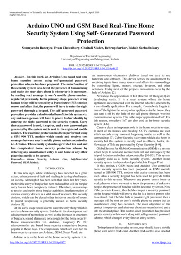
Planning for InstallationLegendA – Main Console UnitB - Motion SensorC - Door/Window SensorD - External Siren/Strobe LightE – Smoke DetectorF - Gas/Propane DetectorG - CO DetectorH - Key Chain Remote ControlZone Construction ChartUse the following chart to help you understand and set zone areas. For example, Door 1 would have adip switch setting of 1 (up) for #1 switch, 0 (down) for #2 switch, 0 (down) for #3 switch and 1 (up) for#4 switch. This chart has designated each alarm sensor as its own zone, however it is possible to use anunlimited number of sensors, all set to operate within the same zone.Switch Positionor ZoneWindow – 1 ( Instantaneous )Window – 2 ( Instantaneous )Window – 3 ( Instantaneous )Window – 4 ( Instantaneous )Window – 5 ( Instantaneous )Door – 1 (delay)Door – 2 (delay)Door – 3 (delay)Room – 1 ( Instantaneous )Room – 2 ( Instantaneous )Room – 3 ( Instantaneous )Gas – 2 ( 24 hour mode)Smoke & Fire (24 hour mode)Gas – 1 ( 24 hour mode )#1#2#3010101010101101011010000011110101Preset in factoryPreset in factoryPreset in Factory9#4Zone No.11111110000Zone 1Zone 2Zone 3Zone 4Zone 5Zone 6Zone 7Zone 8Zone 9Zone 10Zone 11Zone 12Zone 13Zone 14
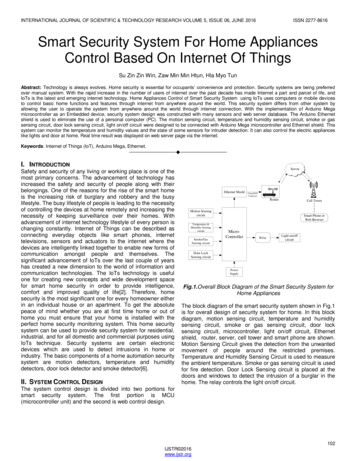
Planning for InstallationSetting the Zone SwitchTo access and change the zone DIP switch, follow these steps:Door/Window SensorTo change the zone setting on a door/window sensor, follow these steps:1. Remove the battery compartment cover and battery.2. Remove the two screws holding the front cover, and expose the green circuit board.3. Locate the 4 pin DIP switch next to the battery clip, and select the appropriate zone setting asshown in the table on page 94. Carefully replace the circuit board to its correct position.5. Re-assemble the sensor covers and replace the batteryAnti-Tamper SwitchPlease note: If the access cover is removed on the door/window contact transmitter, then the alarm willsound ( provided the battery is installed ). This is an anti-tamper system, where as if the anti-tamperswitch ( illustration 1 ) is activated; by removing the cover, then the siren will soundMotion Sensor1. Remove the battery compartment cover and battery2. Remove the two screws holding the front cover, and lift the cover away from the unit, exposing theinside circuit. Be careful not to damage the wiring connected to the LED indicators.3. Locate the 4 pin DIP switch ( located above the 8 pin System ID DIP switch), and select theappropriate zone setting as shown in the table on page 9.4. To the right of the 8 pin ID DIP switch is an OFF/ON/TEST switch:10
OFF – Passive Infrared (PIR) is in the “OFF” statusON - PIR is in the regular mode with a 2 minute idle timeTEST – PIR disables the 2 minute idle time, and works with a 5 –10 second interval( Please note: Factory preset switch is in the “OFF” position5. Carefully replace the circuit board to its correct position6. Re-assemble the sensor covers and replace the batteryAbout the Main ConsoleThe Main Console is the heart of the security system. It monitors sensors and responds according to howit is programmed, whenever an alarm is activated.The controls on the Main Console may look complex at first, however most procedures are straightforward and easy. Please review the illustrations below which label all of the parts of the Main Console.The following is a step-by-step guide for installing and programming the console.We recommend that you install and program the console before installing the other components of thesystem. This is to ensure that all of the components are working together properly11
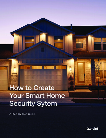
LEGEND1 – REC BUTTON2 - PLAY BUTTON3 - SET BUTTON4 - CLEAR/AUTO BUTTON5 - ENTER/ARM BUTTON6 - NUMERIC KEYPAD7 - MEDICAL EMERGENCY BUTTON8 - FIRE BUTTON9 - BURGLARY BUTTON10 - ALERT/MODE BUTTON11 - PANIC KEY12 - LOW BAT.INDICATOR13 - AUX.OUTPUT TERMINAL JACKS14 - TELEPHONE JACKS15 – TEL.LINE JACK16 - SPEAKER17 – ARMED LED IND.18 - MICROPHONE19 - ANTENNA20 - DC POWER JACK21 - LCD PANEL22 - TEST LED23 - MUTE BUTTON24 - TEST BUTTONAbout the Main ConsoleAbout the MaInstalling the Main ConsoleRemember that the Main Console must have access to a power outlet and to a telephone jack. It alsoperforms better if it is in a position central to the alarm sensors.Mounting the ConsoleMain ConsoleThe Main Console may be set on a tabletop, or mounted on a wall. To mount the console on a wall,follow these steps:1. Locate the four rubber pads on the back of the Main Console. Note that the two pads at the top ofconsole ( towards the antenna ) are removable2. Remove the two top pads and store then away for future use.3. Measure and fix screws into the wall so that the two screws fit into grooves left under the removedpads.4. Set the console onto the screws and carefully allow the console to drop into the grooves securely.Powering the Main ConsoleOnce you are satisfied with the System ID Code, Alarm Zones, and Alarm Period settings, power up theMain Console by following these steps:1. Locate the AC adapter2. Attach the narrow end of the adapter into the connector provided at the back edge of the console, tothe left of the antenna.3. Plug the other end of the adapter into an electrical outlet4. Watch as the LCD screen and the Armed light become active for five seconds and then return toblank/off12
About the Main ConsoleConnecting the Telephone LineCConnectingthe TelephoneTo connect the Main Console to the telephone line, follow these steps:1. Locate the two phone jacks on the back edge of the console. These phone
Sentinel security systems are industry leaders in quality, service, and affordability. . In the normal mode, the auto-dialer and external siren are disabled and only the internal siren on the main console will sound when the system is